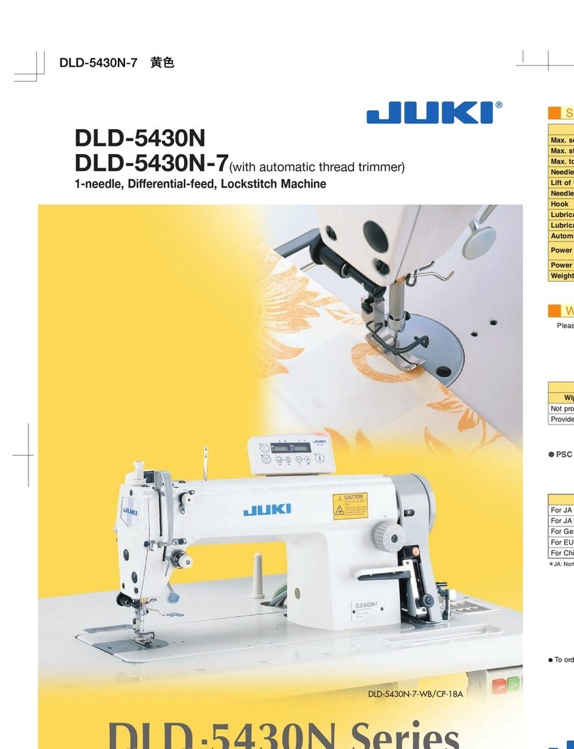
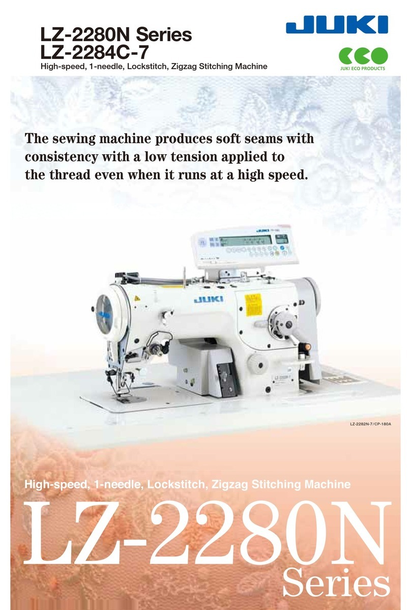
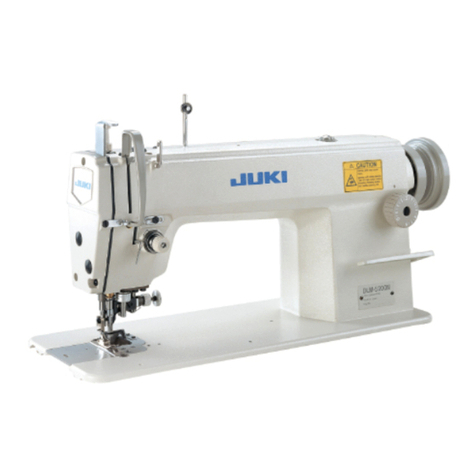
JUKI DDL-8300N User manual

•JUKI
DDL-8300N
INSTRUCTION
MANUAL
MANUAL
DE
INSTRUCCIONES
:
Read
safety
instructions
carefully
and
understand
them
before
using.
Retain
this
instruction
Manual
for
future
reference.
euEnssB'
%
NOTA:
Antes
de
comenzar
a
usar
esta
mdquina
lea
con
detencidn
hasta
comprender
todes
las
InStrudciones
de
sequridad.Conserve
este
Manual
de
instrucciones
a
mano
para
futuras
consulfafs.
No.OO
29348802
From the library of: Superior Sewing Machine & Supply LLC

IMPORTANT
SAFETY
INSTRUCTIONS
Putting sewing
systems
into operation is prohibited until it
has
been ascertained that
the
sewing
systems
in
which
these
sewing machines willbe built into, have conformed with the safety regulations in your country.
Technical service for
those
sewing
systems
is
also
prohibited.
1. Observe the basic safety measures, including, but not limited to
the
following
ones,
whenever you
use
the
machine.
2. Read all
the
instructions, including, but not limited to this Instruction Manual before you
use
the
machine.
In addition,
keep
this
Instruction Manual
so
that
you
may
read
it
at
anytime
when
necessary.
3. Use
the
machine after it
has
been
ascertained
that
it
conforms
with
safety
rules/standards
valid in
your
country.
4.
All
safety devices
must
be in position when
the
machine is ready for work or in operation.
The operation without
the
specified
safety
devices
is
not
allowed.
5. This machine shall be
operated
by appropriately-trained
operators.
6. For your
personai
protection, we
recommend
that
you
wear
safety
glasses.
7. For
the
following,
turn
off
the
power
switch
or
disconnect
the
power
plug
of
the
machine
from
the
receptacle.
7-1 For threading needle(s), looper,
spreader
etc.
and
replacing bobbin.
7-2 For replacing part(s) of needle,
presser
foot,
throat
plate, looper,
spreader,
feed
dog,
needle
guard,folder,
cloth
guide
etc.
7-3
For
repair
work.
7-4 When leaving
the
working
place
or
when
the
working
place
is
unattended.
7-5 When
using
clutch
motors
without
applying
brake,
it
has
to
be
waited
until
the
motor
stopped
totally.
8. If
you
should
allow oil,
grease,
etc.
used
with
the
machine
and
devices
to
come
in
contact
with
your
eyes
or
skin
or
swallow
any
of
such
liquid by mistake, immediateiy
wash
the
contacted
areas
and
consuit
amedical
doctor.
9. Tampering with
the
live
parts
and
devices,
regardless
of
whether
the
machine
is powered, is prohibited.
10. Repair,
remodeling
and
adjustment
works
must
only
be
done
by
appropriately
trained
technicians
or
specially
skilled
personnel.
Only
spare
parts
designated
by JUKI
can
be
used
for
repairs.
11. General
maintenance
and
inspection
works
have
to
be
done
by
appropriately
trained
personnel.
12.
Repair
and
maintenance
works
of
electrical
components
shall
be
conducted
by
qualified
electric
technicians
or
under
the
audit
and
guidance
of
specially
skilled
personnel.
Whenever
you
find a failure of
any
of electrical
components,
immediately
stop
the
machine.
13.
Before
making
repair
and
maintenance
works
on
the
machine
equipped
with
pneumatic
parts
such
as
an
air
cylinder,
the
air
compressor
has
to
be
detached
from
the
machine
and
the
compressed
air
supply
has
to
be
cut
off. Existing residual air
pressure
after
disconnecting
the
air
compressor
from
the
machine
has
to
be
expelled.
Exceptions
to
this
are
only
adjustments
and
performance
checks
done
by
appropriately
trained
technicians
or
specially
skilled
personnel.
14. Periodically clean
the
machine
throughout
the
period of
use.
15.
Grounding
the
machine
is
aiways
necessary
for
the
normal
operation
of
the
machine.
The
machine
has
to
be
operated
in
an
environment
that
is
free
from
strong
noise
sources
such
as
high-frequency
welder.
16. An appropriate power plug
has
to
be
attached
to
the
machine
by electric
technicians.
Power
plug
has
to
be
connected
to
a
grounded
receptacle.
17.
The
machine
is
only
allowed
to
t>e
used
for
the
purpose
intended.
Other
used
are
not
allowed.
18. Remodel
or
modify
the
machine
in
accordance
with
the
safety
rules/standards
while
taking
all
the
effective
safety
measures.
JUKI
assumes
no responsibility for
damage
caused
by remodeling
or
modification of
the
machine.
19. Warning
hints
are
marked
with
the
two
shown
symbols.
A
Danger
of
injury
to
operator
or
service
staff
A
items
requiring
special
attention
From the library of: Superior Sewing Machine & Supply LLC

mm
•a
w^iaii««ii±
-
6. '
liiiisssesaiBB^
°
7. '
ffillilBP^tSli^liM
'
^tRTS^iSSP
o
7-2
^
sn
>
$t«
>
ii$t
>
^8!S
^ ^
iitts
^ ^
?)i9i£gs^^
<>
7-3
mmm'
7-4
If^®m«A7aKISMIf^®Hffif
•>
7-5
{£ffil9ldsa^
'
il:;^^Siie
°
8. ^
iSiiii^iSS9ISAiBISlE^iiJlSa±^'
§l(»S«fK^ •ffilc
11.
-i3s»i%if^gsiB^si§i)iispe^An^ii{7<>
13.
(is
^ ^ °
in^ssnsg^iR^'
o
14.
<•
16.
aagaMSfflaBSAHP^aiiiwAasgii»s^ag!^^ggijgsas±
<•
17.
°
5?p'
'JUKI
°
19.
2|s:®fflgiB0»±SgfflmT2(l^??SSI»
A
=AjM^^f^AA
^
ig(iAea^)gRei
<>
A
From the library of: Superior Sewing Machine & Supply LLC

INSTRUCCIONESIMPORTANTES
DE
SEGURIDAO
Est§prohibido poneren operacidnla
mdquina
do coser hasta no cerciorarse de que los sistemas de eosido en
losqueeatetipode
mdquinas
se tienenqueIncorporar, estdnen
conformidad
conlas requlaciones deseguridad
vigentes en su pafs. Tambi^nestd prohibidoel servicio t^cnlco para estosalstemasde cosido.
1.Observela medidas b^slcas de seguridad, Incluyendo, pero no llmlt^ndose, a las siguientes, slempreque
use
la
mdquina.
2. Lea todas las Instrucciones, Incluyendo, pero no llmitdndose a
este
Manualde Instrucciones,
antes
de usar
la mdqulna. Ademds, guarde este
Manual
de Instrucciones de mode que usted lo pueda leer cuando sea
necesarlo.
3. Use la mdquina despu6s de halierse cerciorado de que
se
conforms a las reglas y normas de seguridad
v^lldasen
su
pals.
4.Todos los dispositlvos de seguridad deben estar en posicldn cuando la m^quina estd lists para entrar en
servicio o ya estd en operacidn. Noestd permltido operar la mdqulna sin los dispositlvos de seguridad
especlficados.
5. Esta mdquina
debe
ser
operada
per
operadores
debldamente entrenados.
6. Para la proteccldn del personal, recomendamos la colocacidn de gafas de seguridad.
7. Para losigulente,desconecte laalimentacldn odesconecteel cablede allmentacldn de lamdqulnadesde latoma.
7-1 Parael enhebrado de la(s) aguja(s), enlazador, estlradora, etc., ypara el reemplazo de la boblna.
7-2 Parael reemplazo
de
las
piezas de la aguja, prensatelas, placa
de
agujas, enlazador, estiradora,dentado
de
transporte, protector
de
aguja, plegador, gufa
de
tela,
etc.
7-3
Para
los
trabajos
de
reparo.
7-4 Aldejar el lugar de trabajo o
cuando
el lugar de trabajo
estd
desatendido.
7-5Cuando usemotores de embraguesin aplicarelfreno,
se
debeesperarhastaque el motor pare totalmente.
8. En
case
de que el aceite, grasa, etc. que
se
usa en
su
mdquina y dispositlvos toque
sus
ojos o plel, o que
trague
por
desculdo
cualquier
Ifquido
semejante,
Idvese
Inmediatamente
las
partes
afectadas
o
consults
a
un
m6dlco.
9. Est4prohibido
manipular
laspiezasydispositivosmdviles mientrasest§conectadalacorrlenteelectricsa lam^uina.
10. Los
trabajos
de reparo, remodelacldn y
ajuste
se
deben
hacer
solamente
por
tdcnicos
debfdamente
entrenados
o
por
personal
especlallzado.
Para los reparos,
se
pueden utilizar solamente las piezas de repuesto deslgnadas porJUKI.
11. Los trabajos de mantenlmiento einspeccidn
generales
se
deben
llevar a
cabo
por personal debldamente
entrenado.
12. Los trabajos
de
reparo ymantenlmiento
de
los
componentes
el^ctricos
se
deben
conduclr
por
t4cnicos
eldctricos callflcados o bajo la veriflcacldn y direccidn de personal especlallzado.
Slempre
que
descubra
una
falla
en
cualquier
componente
el6ctrlco,
pare
Inmediatamente la mdqulna.
13.
Antes
de
llevar a
cabo
los
trabajos
de
reparo
y
mantenlmiento
en
la
mdqulna
equipada
con
piezas
neumdticas,
tales
como
un clllndro
de
aire,
se
debe
desmontar
el
compresor
de
aire
desde
la mdqulna, y
tambl^n
se
dabe
cortar
el
sumlnlstro
de
aire comprlmido. Adem^s,
se
del>e
expeler
la
presidn
de
aire
existente
despuds
de
la desconexidn
de
la m^qulna. Las
excepclones
para
eso
son
solamente
los
ajustes
y
verificaclones de rendimiento
que
se
hacen
por t6cnlcos debldamente
entrenados
o por personalespeclallzado.
14. Llmple
perlddicamente
la
m^qulna
durante
todo
el perfodo
de
use.
15. La
puesta
atierra de la m^qulna
es
slempre
necesarlo
para la operacidn normal de la misma.
La
m^qulna
deberd
ser
operada
en
un
amblente
exento
de
ruidos
fuertes
tales
como
en
lugares
de
soldadura
de
alta
frecuencla.
16.
Los
t^cnlcos
el6ctricos
del)er6n
montar
en
la
mdquina
un
enchufe
aproplado
para
la
corrlente
el^ctrlca.
El
enchufe
de
la
corrlente
el4ctrlca
se
deberd
conectar
a
un
tomaconiente
conectado
a
tierra.
17.
S6lo
se
puede
utilizar
esta
mdqulna
para
el
propdsito
que
fue fabrlcada. No
se
permiten
otros
uses.
18.
Remodels
omodlfique la
mdqulna
de
acuerdo
a
las
normas
y
reglas
de
seguridad
mientras
toma
todas
las
medidas
de
seguridad
efectivamente.
JUKI no
asume
ninguna
responsabllldad
por
dahos
causados
por
la
remodelacldn
omodificacidn
de
la mdqulna.
19.
Los
puntos
de
advertencia
estdn
marcados
con
los
dos
sfmbolos
mostrados.
A
Peligro
de
lesldn
al
operador
o
personal
de
servicio
A
Itemes
que
requleren
atencldn
especial
III
From the library of: Superior Sewing Machine & Supply LLC

A
FOR
SAFE
OPERATION
1. Don't put your hand under
the
needle when you turn "on"
the
power switch or operate
the
machine.
2. Don't
put
your
hand
into
the
thread
take-up
cover
while
the
machine is running.
3. Turn OFF
the
powerswitch before tilting
the
machine
head
or removing
the
belt cover
and
the
V
belt.
4. Never bring yourfingers, hair or clothing
close
to, or place anything on
the
handwheei,
V-belt,
bobbin
winder
wheel
or
motor
during
operation.
5. If
your
machine
is
provided
with a
belt
cover,
finger
guard
and
safety
plate,
never
operate
your
machine
with
any
of
them
removed.
6. The hook rotatesat a high
speed
while
the
machine is in operation. To preventpossible
injury to
hands,
be
sure
to keep
your
hands
away from
the
vicinity of
the
hook during
operation. In addition, be
sure
to turn OFF
the
power to
the
machine when replacing
the
bobbin.
7. When tilting
the
machine head,
exercise
care
not
to allow
your
fingers etc. to
be
caught
under
the
machine
head.
8. Do
not
wipe
the
surface
of
the
machine
head
with
lacquer
thinner.
9.
Never
operate
the
machine
unless
its
oil
pan
has
been
filled with oil.
10. Don't
use
a motor pulley of a largeroutsidediameterthan
the
standardoutsidediameter
for
the
first
one
month.
11. Confirm
that
the
voltage
and
phase
(single-
or
3-phase)
are
correct
by checking them
against
the
ratings
shown
on
the
motor
nameplate.
12. In
case
of
maintenance,
inspection,
or
repair,
be
sure
to
turn
OFF
the
power
switch
and
confirm
that
the
sewing
machine
and
the
motor
have
completely
stopped
before
starting
the
work. (In
case
of
the
clutch
motor, it
continues
rotating for a while by
the
inertia
even
after
turning
OFF
the
power
switch.
So,
be
careful.)
CAUTION
BEFORE
OPERATION
A
WARNING:
To avoid malfunction
and
damage
of
the
machine, confirm
the
following.
•Clean
the
sewing
machine
thoroughly
before
using
it for
the
first time.
•
Remove
all
dust
collected
on
the
sewing
machine
during
the
transportation.
•Confirm
that
the
voitage
and
phase
are
correct.
•
Confirm
that
the
power
piug
is
properly
connected.
•Never
use
the
sewing
machine
in
the
state
where
the
voltage
type
is
differentfrom
the
designated
one.
•
The
direction
of
rotation
of
the
sewing
machine
is
counterclockwise
as
observed
from
the
handwheei
side.
Be
careful
not
to
rotate
it
in
reverse
direction.
IV
From the library of: Superior Sewing Machine & Supply LLC

At
4s
i
1
i
i ' ^
^ "
CN
-< ® ^ ' -<
Mm
•^i^
M
h K h ^
ho
mm
m>
m^
O
Hh
d+i
IK
K-
£
m
1:
m
IK
m
m
m m
m
m
Hh
I
I
m
m
fr
It
gSil
I i
K- 11
IS
!&8
g §
m
OK
Hh
M
h
II
«o
m
m
m
m
m
fl-
^ o
m m
[1
m
IS
m
m
m ^
§K
M
i|
o
EE
^m
m
h iff K-
n m E
i m
89 K
I I
i
K-
Si IS
m 4
S "c
m @
^ -
^ s
fm
B
m ^
m
DB
is
i!
•-
<S
o
lel
If
m
O g
in
dR
m %
EE
^
^ o
K"
^
^ o ^
li
aa ^ o IS ^ ^
« w ^ " a
@ 4;:
KD
N %
m
ea
bh IS s
I
From the library of: Superior Sewing Machine & Supply LLC

A
PARA
OPERACION
SEGURA
1. No
coloque
su
mano
debajo
de
la
aguja
cuando
poslcione
en
ON el
interrupter
de
la
corriente
o
cuando
opera
la
m^qulna
de
coser.
2. No
coloque
su
mano
en
la
cublerta
del
tira-hilos
mientras
la
maquina
este
en
operacion.
3. No
se
olvide
de
desconectar
la
corriente
antes
de
Inclinar
el
cabezal
de
la
maquina
hacia
atras
o
de
cambiar
la
cublerta
de
la
correa
o
la
correa
en
V.
4. Nunca
ponga
sus
dedos,
cabello
ni
vestidos
ni
ningun
objeto
cerca
o
encima
del volante,
correa
en
V,
bobinadora
o
motor
durante
la
operacion.
5. Si la
maquina
estd
equipada
con
una
cublerta
de
correa,
protector
de
dedos,
protector
de
ojos
y
placa
de
seguridad,
nunca
opere
su
maquina
sin
cualquiera
de
estos
protectores.
6. El
gancho
gira
a
alta
velocidad
cuando
la
maquina
de
coser
est^
funcionado.
Para
evitar
posibles
lesiones
en
sus
manos,
cerciorese
de
mantenerlas
lejos
del
gancho
durante
la
operacion.
Ademas,
cerciorese
de
desconectar
de
la
maquina
la
corriente
electrica
cuando
reemplace
la
bobina.
7.
Antes
de
insertar/extraer
el
conector
de
la
corriente
electrica
debe
posicionar
de
antemano
sin
falta
en
OFF
el
interrupter
de
alimentacion.
8. No
frote
la
superficie
del
cabezal
de
la
mdquina
con
diluyente
de
laca.
9.
Nunca
opere
la
maquina
a
no
ser
que
el
carter
de
aceite
est6
lleno
de
aceite.
10.
Durante
el
primer,
no
use
una
polea
de
motor
cuyo
diametro
exterior
sea
mayor
que
el
diametro
exterior
estdndar.
11.
Confirme
que
tanto
la
tensidn
como
la
fase
monofdsica
o
trifasica)
son
las
correctas
observando
los
valores
nominates
que
van
escritos
en
la
etiqueta
del
motor.
12. En el
caso
de
mantenimiento,
inspeccion
o
reparacion,
cercidrese
de
posicionar
en
OFF el
interrupter
de
la
corriente
electrica
y
de
confirmar
que
la
maquina
de
coser
y el
motor
se
ban
parade
completamente
antes
de
comenzar
el
trabajo.
(En
el
caso
de
motor
de
embrague,
dste
continua
girando
per
un
tiempo
debido
a la
inercia
aun
despuds
de
haber
posicionado
en
OFF
el
interrupter,
Asi
que
tenga
cuidado.)
PRECAUCIONES
ANTES
DE
LA
OPERACION
A
PRECAUCION
:
Compruebe
los
siguientes
ftemes
para
evitar mal
funcionamiento
o
dahos
de
la
tndquina
de
coser.
•Limple
bien
la
mdquina
de
coser antes
de
usaria
per
primera
vez.
•
Quite
blen
el
polvo
acumulado
durante
el
transporte.
•
Conflrma
que
el
voltaje
y la
fase
son
los
correctos.
•
Confirme
que
el
enchufe
esta
blen
conectado.
•
Nunca
use
la
mdqulna
de
coser
en
el
estado
en
que
el
tipo
de
voltaje
sea
diferente
del
deslgnado.
• La direccion
rotacional
de
la
mdquina
de
coser
es
hacia
la izquierda
si
se
observe
desde
el
lado
del
volante.
Tenga
cuidado
en
no
giraria
en
direccidn
inverse.
VI
From the library of: Superior Sewing Machine & Supply LLC

CONTENTS
1.
SPECIFICATIONS
1
2.
INSTALLATION
1
3.
INSTALLING
THE
BELT
COVER
AND
THE
BOBBIN
WINDER
2
4.
ADJUSTING
THE
HEIGHT
OF
THE
KNEE
LIFTER
3
5.
INSTALLING
THE
THREAD
STAND
3
6.
LUBRICATION
4
7. ADJUSTINGTHE
AMOUNT
OF OIL(OILSPLASHES)
IN
THE HOOK 5
8.
ATTACHING
THE
NEEDLE
7
9.
SETTING
THE
BOBBIN
INTO
THE
BOBBIN
CASE
7
10.
ADJUSTING
THE
STITCH
LENGTH
7
11.
PRESSER
FOOT
PRESSURE
8
12.
HAND
LIFTER
8
13.
ADJUSTING
THE
HEIGHT
OF
THE
PRESSER
BAR
8
14.
THREADING
THE
MACHINE
HEAD
9
15.
THREAD
TENSION
9
16.
THREAD
TAKE-UP
SPRING
10
17.
ADJUSTING
THE
THREAD
TAKE-UP
STROKE
10
18.
NEEDLE-TO-HOOK
RELATIONSHIP
11
19.
HEIGHT
OF
THE
FEED
DOG
12
20.
TILT
OF
THE
FEED
DOG
13
21.
ADJUSTING
THE
FEED
TIMING
14
22.
MOTOR
PULLEYS
AND
BELTS
15
m m
1. 1
2. i
3.
2
4.
3
5. 3
6.
4
7.
m)
mmyjm
5
8. 7
9. 7
10.
mmmmmmm
7
11. 8
12. 8
13. 8
14. 9
15. 9
16. 10
17.
^HaanisaBa^iasi
10
18. "
19. 12
20.
13
21. 14
22. 15
VII
From the library of: Superior Sewing Machine & Supply LLC

INDICE
1.
ESPECIFICACIONES
1
2.
INSTALACION
1
3.
INSTALACION
DE
LA
CUBIERTA
DE
LA
CORREA
Y
LA
BOBINADORA
2
4.
AJUSTE
DE
LA
ALTURA
DEL
ELEVADOR
DE
RODILLA
3
5.
INSTALACION
DEL
PEDESTAL
DEL
HILO
3
6.
LUBRICACION
4
7.
AJUSTE
DE
LA
CANTIDAD
DE
ACEITE
(MANCHAS DE ACEITE) EN EL GANCHO 5
8.
COLOCACION
DE
LA
AGUJA
7
9.
MODO
DE
FIJAR
LA
BOBINA
EN
LA
CAPSULA
DE
CANILLA
7
10.
MODO
DE
AJUSTAR
LA
LONGITUD
DE
PUNTADA
7
11.
PRESION
DEL
PRENSATELAS
8
12.
ELEVADOR
MANUAL
8
13.
AJUSTE
DE
LA
ALTURA
DE
LA
BARRA
DEL
PRENSATELAS
8
14.
ENHEBRADO
DE
LA
MAQUINA
9
15.
TENSION
DEL
HILO
9
16.
RESORTE
RECOGEDOR
DEL
HILO
10
17.
AJUSTE
DEL
RECORRIDO
DEL
RECOGEDOR
DEL
HILO
10
18.
RELACION
DE
AGUJA
A
GANCHO
11
19.
ALTURA
DE
LOS
DIENTES
DE
ARRASTRE
12
20.
INCLINACION
DE
LOS
DIENTES
DE
ARRASTRE
13
21.
AJUSTE
DEL
SONCRONISMO
DEL
ARRASTRE
DE
LAS
TELAS
14
22.
POLEAS
Y
CORREAS
DEL
MOTOR
15
VIII
From the library of: Superior Sewing Machine & Supply LLC

1.
SPECIFICATIONS
/ /
ESPECIFICACIONES
DDL-8300N
DDL-8300NH
Application For medium-weight materials For heavy-weight materials
Sewing
speed
Max. 5,500 rpm Max.
4,000
rpm
Stitch length
Max.
5
mm
Max.
5
mm
Needle
OBx
1
#9
to
#18
DB
X 1
#20
to
#23
Presserfoot
lift
(byknee
lifter)
10 mm (Standard) 13 mm (Max.) 10 mm (Standard) 13 mm (Max.)
Lubricating oil
JUKI
Machine
Oil
7
Noise
Workplace-related noise at sewing
speed
n = 4,500 min*:
Lpa
^ 83 dB (A)
Noise measurement according to DIN45635-48-A-1.
DDL-8300N
DDL-8300NH
m m
tpmn
•
mn
5,5(X)rpm
4,000
rpm
5
mm
5
mm
m tt-
DBxl
#9---#18
DBxl
#20~#23
10
mm
13
mm
10mm
13mm
7 JUKI
mm
DDL-8300N
DDL-8300NH
Aplicacidn
Para
materiaies
de
peso
medio
Para
materiaies
pesados
Velocidad
de
coser
Mdx.
5.500
p.p.m.
MAX.
4.000
p.p.m.
Largo
de
la
puntada
Mdx.
5
mm
Mdx.
5
mm
Aguja
DBx
1
#9a#18
DB
X 1
#20
a
#23
Bevacidndelpie prensatelas
(mecfante elelevadorde la
rocfiia)
10 mm (est8ndar)
13
mm
(mdx.)
10 mm (estdndar)
13 mm
(m^.)
Aceite
lubricante
JUKI
Machine
Oil
7
Ruido
Nivel
de
ruido ralacionado
con
el
puesto
de
trabajo avelocidad
de
costura
n = 4.500 min
';
Mediddn
de
ruido
Lpa
83 dB (A)en conformidad con DIN45635-48-A-1.
2.
INSTALLATION
/
INSTALACION
o o
22.5
mm
J
18.5
mm
T\
e
o
o
From the library of: Superior Sewing Machine & Supply LLC

(1) Installing
the
oil
pan
1) The oilpan should rest on the four
comers
of the machine table groove.
2)
Fix
two
rubber
seatsO onsideO
(operator's
side)
using
nails
O as
illustrated
above.
Fix
two
cushion
seats
O onside®
(hinged
side)
using
a
rubber-based
adhesive.
Then
place
oil
panO onthe
fixed
seats.
3)
Fit
hinge
O
into
the
opening
in
the
machine
bed,
and
fit
the
machine
head
to
table
rubber
hinge
O
before
placing
the machinehead on cushions0 on the fourcomers.
(1)
ffiOSJffNS
•
«Sm}ESffifOK(±i
•>
(1)
instaiacion
del
colector
de
aceite
1)
El
Carterdel aceite debe descansar en las 4 esquinas de laabertura de la mesa de la m^quina.
2)
Como
muestra la
figura,
coloque
almohadillas
de gomaO en el ladoO
(lado
de la
operaria)
usando
clavos
O.
Fije
las
almohadillas
de gomaO en el ladoO
(lado
de labisagra) usando unadhesivo con
base de goma.
Luego
coloqueel carterdelaceite O en las almohadillas.
3) Para colocarla m^quina,
primero
introduzca la bisagra O en la abertura de la base de la m^quina, y
luego
alineela
mdquina
con las bisagrasde gomade la mesa O antes de apoyarla
m^quina
en las
almohadillasO puestas en las 4 esquinas.
3.
INSTALLING
THE
BELT
COVER
AND
THE
BOBBIN
WINDER
/
INSTALACION
DE
LA
CUBIERTA
DE
LA
CORREA
Y LA
BOBINADORA
A
WARNING:
Toavoidpossible personal injurydueto abrupt start ofthe machine,tum offthe powertothe machine
and
check
to
be
sure
that
the
motor
has
totally
stopped
rotating In prior.
AVISO:
Paraevitar posibles leslones pefsonales debldo a un arranque brusco de la m^qulna,desconecte la
corrlenteelectricade la maqulnay compruebede antemano para mayorsegurldad qua el motorestd
completamente
parado.
0
From the library of: Superior Sewing Machine & Supply LLC

4.
ADJUSTING
THE
HEIGHT
OF
THE
KNEE
LIFTER
/
AJUSTE
DE
LA
ALTURA
DEL
ELEVADOR
DE
RODILLA
WARNING:
Toavoid possible personal Injurydueto abruptstartofthe machine, turn offthe power to the machine
^
i^otor
has
totally
stopped
rotating In prior.
' '
mmnmm
> °
AVISO:
Para evitar poslbles leslones personalesdebldo a un arranque brusco de la mdqulna, desconecte la
corrlenteel6ctrica de la m^qulna y compruebe
de
antemano para mayor seguridad
qua
el motor estd
completamente
parado.
0
1) The standard height of the
presser
foot liftedusing the knee lifteris 10 mm.
2) Youcan adjust the presserfoot
lift
up to 13 mm using knee
lifter
adjust screw O •
3) When you have adjusted the presserfoot
lift
to over 10 mm, be sure that the bottomend of needle bar <
inits lowestpositiondoes not hitpresserfoot
O.
2)
13 mm -
3)
lOnrni
1) La altura normal
que
se
eleva
el pie prensatelas
usando
el elevador
de
rodilla
es
10 mm.
2) Usandoel
tomillo
de ajuste
O,
Ud.puede ajustar laelevacidndel pieprensatelas usando elelevadorde
rodilla
hasta
un
m^imo
de
13
mm.
3) Cuando
ha
ajustado la elevacidn del pie
prensatelas
a
mds
de
10 mm,
asegurese
que
el extreme inferior
de labarra de la aguja
O,
al estar en su posicidn mds baja, no choca con el pieprensatelas
0.
5.
INSTALLING
THE
THREAD
STAND
//
INSTALACION
DEL
PEDESTAL
DEL
HILO
From the library of: Superior Sewing Machine & Supply LLC

6.
LUBRICATION
/
LUBRICACION
A
WARNING:
To
avoid
possible
personal
injury
dueto
abrupt
startofthe
machine,
turn
off
the
power
tothe
machine
and
check
to
be
sure
that
the
motor
has
totally
stopped
rotating in prior.
AVISO:
Para
evitar
posibies lesionespersonales debido a unarranque bruscodela
mdquina,
desconecte la
corriente
el^ctrica
dela
m^quina
y
compruebe
de
antemano
para
mayor
seguiidad
queel
motor
estd
completamente parado.
(I)
1)
S#}E
7 JUKI
Oa
• —1
2)
ttlfWttH^HLOwsleSJUT©
•
3)
4)
(1) information
on
Subrication
1)
Fill
oil
panO
with
JUKI
Machine
Oil
7 upto
HIGH
markO.
2)
When
the
oil
level
lowers
below
LOW
mark
refill
the
oil
pan
with
the
specified oil.
3) Whenyouoperate the machine after
lubrication,
you
will
see
splashing
oil
through
oil
sight
window
O if
the
lubrication Is
adequate.
4) Note that the amount of the splashing oil Is
unrelated
to
the
amount
of
the
lubricating oil.
^
When
you
first
operate
your
machln^
I
after
setup
or
after
an
extended
period
I
of disuse, run your machine at 3,000 |
rpm.
for about 10 minutes for the |
'
purpose
of
break-in.
^
ri
;SnSJ
HIGH
©SBOWffiB
•
•
ffiHr
10
dfi
3,000
n>n.»SdS$S
I
(1)
informacidn
sc ia
iubricaclon
1)
Llene
el
colector
site
O
con
aceite
JUKI
Machine
Oil
7
hasta
la
marca
"HIGH"
O •
2)
SI
el
nivel
del
acek«ro^a dela
marca
"LOW"
0,
rellene
el
colector
de
aceite
con
el
aceite
especlflcado.
3)
81
elsistemade
lubrlcaclbn
estd
funcionando
blen,
alhacer
funclonar
la
m^qulna,
puedeversesalplcar
el
aceite
a
trav^s
de
la mirilla del
aceite
0.
4) Observeque lacantldadque salpicael aceite notiene
relacidn
con lacantldad de aceite
lubrlcante.
rAterTcidn
Cuando
use
ia
m^uina
per
primera
voz
despues
do
su
instalacidn
y
preparacidn
o
despue^|
' i I
que
no
la
haya
usado
por
mucho
tiempo,
haga
funcionar
ia
mdquina
a
una
velocidad
de.
'
\^py
3.000
p.p.m.duranteunos
10
minutos.
j
0
Maximum
Minimum
HA
H'J^
Mdxiomo
Minimo
1
(2) Adjusting
the
amount of oil supplied
to
the
face
plate
parts
1)
Adjust
the amountof
oil
suppliedtothe thread take-
up
and
needle
bar
crank
0
by
turning
adjust
pin
O.
2) The
minimum
amountof
oil
Isreachedwhenmarker
dotO
Is
brought
closeto needlebar
crank
0 by
turning
the adjust
pin
In
direction
0.
3)
The
maximum
amount
of oil Is
reached
when
markerdotO Isbroughtto the position justopposite
from the needle bar crank by turning the adjust pin
In direction
0.
From the library of: Superior Sewing Machine & Supply LLC

(2)
(2)
Ajuste
de
la
cantidad
de
aceite
suministrada
a
ios
componentes
de
la
placa
frontal
1) Lacantidad de aceite suministrada a Ios componentes recogedores del hiloy a la biela de la barra de la
aguja e se ajusta girando el vastago de ajuste
O.
2) Lacantidad
minima
de aceite
se
logracuando el puntomarcadorO
se
muevehasta estar lomas cerca
posible de la biela de la barra de la aguja
O.
Para ello,
es
necesario girar el vastago de ajuste en la
direccibn
0.
3}
Lacantidad maximade aceite
se
obtiene cuando el punto marcador O
Hega
a la posicidnexactamente
opuestadesde el
ciguenal
de labarrade aguja
girando
elesparragode ajusteen la
direccion
®.
7. ADJUSTING THE AMOUNT
OF
OIL (OIL
SPLASHES)
IN
THE HOOK
mnmmmM
(ii!)
AJUSTEDELA
CANTIDAD
DE
ACEITE
(MANCHAS
DE
ACEITE)
ENEL
GANCHO
A
WARNING
:
Be extremely careful
about
the
operation of
the
machine
since
the
amount of oil
has
to be checked by
turning
the
hook
at
a
high
speed.
}±m
AVISO:
Ponga
sumo
cuidado
acerca
de la operacldn
de
la maquina
de
coser
dado
que
la cantidad
de
aceite
se
debe
comprobar
girando
el
gancho
a
alta
velocidad.
0 Amount of oil (oilsplashes) confirmation paper
m)
Papel
de
confirmacidn
de
cantidad
de
aceite
(manchas
de
aceite)
d)
Position
to
confirm
the
amount
of oil (oil
splashes)
(Si)
BigtSlS
Posicidn
para
confirmar ia
cantidad
de
aceite
(manchas
de
aceite)
70
mm
/)
7m
9
V
1 /
Oil
splashes
confirmation
paper
Papei
de
confirmacion
de
manchas
de
aceite
Closeiyfit
the
paper
against
the
wall
surface
of
the
bed.
Pegue
el
papel
contra
la
pared
del
depdsito
de
aceite.
*
When
carrying
outthe
procedure
desciitied
below
in2,
remove
the
slide
plate
andtake
extreme
caution
notto
allow
your fingers to
come
incontact withthe hook.
1)
if
the
machine
has notbeen
sufficiently
warmed
upfor
operation,
makethe
machine
run
idle
for
approximately
three minutes. (Moderate intermittentoperation)
2) Placethe
amount
of
oil
(oil
splashes)
confirmation
paperunderthe
hook
while
the
sewing
machine
is
in
operation.
3)
Confirm
the
height
ofthe
oil
surfaceinthe
oil
reservoir
is
within
the rangebetween
"HIGH"
and
"LOW".
4)
Confirmation
ofthe
amount
of
oil
should
be
completed
in
five
seconds.
(Check
the
period
of
time
with
a
watch.)
5itfT^0
2)
o
'
mmn
3 )
HIGH m LOW
6^|g@0;tP9
°
mm^m
»)
mmmm)
*
1)
2)
3)
4)
From the library of: Superior Sewing Machine & Supply LLC

*
Cuando
ejecute
el
prooedlmiento
descrito
a
continuacion
en2,
quite
laplaca
deslizante
y
ponga
sumo
cuidado
en
que
BUS
dedos
no toquen el gancho.
1) Sila
m^quina
nohasido
oalentada
lo
suficiente
parasuoperaddn, hagaquela
m^quina
marche
en
vacfo
durarrte
aproximadamente tres minutos (funcbnamlento
Intemnitente
moderado).
2)
Coloque
elpapelde
confirmacidn
de lacantldad de aceite(manchasde
aceite)
debayo
delgancho
inmedlatamente
despu^s
que
se
detenga la m^quina.
3)
Confirme
quela
altura
del
nivel
de aceiteen el
depdsito
deaceitese encuentre
dentro
de lagama
"HI"
y
"LOW".
4) La
confiimacidn
de la
cantldad
de aceitedebeefectuarse en dnco segundos
(Chequee
el
tiempo
conun
reloj.)
Sampleshowing
the
appropriate amount of oil /
Bn'
Ejempio
que
muestra
ia
cantidad
de
aceite
apropiada
1) The
amount
of
oil
shown
in
thesamplesonthe
left
should
Splashes
of
oil
from
the
hook
/ /
El
aceite
salpica
desde
el
gancho
I
1
t
1
1
mm
(DDL-8300NH: 1
mm)
Appropriate
amount
of
oil
(small)
Cantldad
apropiada
de
aceite
(pequeha)
Splashes
of oil
from
the
hook
/ /
El
aceite
salpica
desde
el
gancho
y
2
mm
(DDL-8300NH: 3
mm)
Appropriate
amount
of oil (large)
mwmu
(A)
Cantldad
apropiada
de
aceite
(grande)
be
finely
adjustedinaccordance
with
sewingprocesses.
Be careful not to excessively increase/decrease the
amount of oilinthe hook.
(If
the amount of
oil
istoo
small,
the
hook
will
be
seiz^
(the
hook
will
be
hot).
If
the
amountofoilIstoo much,
the
sewing product may
be
stainedwithoil.)
2)
Adjust
theamountof
oil
In
thehooksothatthe
oil
amount
(oil
splashes)
should
notchange
while
checking
the
oil
amountthree times(onthethree sheets ofpaper).
2)
mm
(»)
mjsm3>x
1) La
cantidad
de aceitequese muestra en losejemplos
de la izquierda
se
deberd ajustar a precisibn en
coiTfoimidadconlosprocesosdecosido. Pongacuidado
en
no
aumentar/disminuir
excesivamente
la
cantidad
de aceite en el gancho. (Si la cantldad de aceite
es
insuficiente, el gancho
se
agarrotarS (el gancho
recalentard). Si la cantidadde aceite es excesiva, la
prendadelcosido
se
manchardcon aceite.)
2) Ajusteia
cantidad
de aceiteenelganchode modeque
la cantidad de aceite (salpiquede aceite) no deber^
cambiaralcomprobartresveces lacantidadde aceite
(en las tres hojas
de
papel).
•Adjusting
the
amount of oil (oil spots) in
the
hook/t&WAJi
AJuste
de
ia
cantidad
de
aceite
(manchas
de
aceite)
en
ei
gancho
1) Tumingthe oilamount adjustment screw attached
on the hook drivingshaft front bushing inthe"+"
direction (indirection
O)
will
increase the amount
of oil
(oil
spots) inthe hook, or in
thedirection
(indirection
O)
will
decrease
it.
2)
After
the amountof
oil
inthe hookhas been properly
adjusted
with
the
oil
amount
adjustment screw,
makethe sewingmachinerunidleforapproximately
30
seconds
to
check
the
amount
of oil In
the
hook.
2)
1)
mm
•
mm
im)
*
iri-6^:^
1^
(®:^i^)
mm^mm
m)
1)
Al
girarel
tomillo
de ajuste de la cantidad de aceite
fijado
al bujefrontal del eje impulsordel gancho en
direccibn"+" (en direccibn
O)
aumentard la cantidad de aceite (manchas de aceite) en el gancho, yen
la
direccldn(en
direccibn
0),
la disminuird.
2) Despu^s que la cantidad de aceite en el gancho haya sido ajustada apropiadamente con el
tomillo
de
ajustede lacantidadde aceite, haga que la
irWiquina
de coser marcheen vacfoduranteaproximadamente
30
segundos
para
chequear
la
cantidad
de
aceite
en
ei
gancho.
From the library of: Superior Sewing Machine & Supply LLC

8.
ATTACHING
THE
NEEDLE
/ /
COLOCACION
DE
LA
AGUJA
A
WARNING:
To avoid
possible
personal
injury
due
to
abrupt
start
of
the
machine,
turn
off
the
power
to
the
machine
and
check
to
be
sure
that
the
motor
has
totally
stopped
rotating in prior.
AVISO:
Para
evitar
posibles
iesiones
personales
debido
a un
arranque
brusco
de
la mdquina,
desconecte
la
corrienteelTOtrica
de
la mdquina y
compruebe
de
antemano
para
mayor
seguridad
que
el motor
esta
completamente
parado.
9.
SETTING
THE
BOBBIN
INTO
THE
BOBBIN
CASE
/ /
MODO
DE
FIJAR
LA
BOBINA
EN
LA
CAPSULA
DE
CANILLA
1) Pass the thread throughthread slit
O.
and
pull
the
thread
in
direction
Byso doing, the thread
will
pass
under the tension
spring
andcomeout
from
notch
0.
2) Check that the bobbin rotates in the direction of
the arrow when thread 0 is pulled.
1)
ies^iiaasw^ssa©
•
2)
aisM®
• -
1) Rase el
hilo
porla rendija O de
hilo,
ytiredel
hilo
en la direccidn
0.
De
este
modo, el hilo
pasard
por debajo del muelle
tensorysaldraporlamuesca
0.
2) Compruebe que la bobina gira en la direccibn de
la flecha
cuando
se
tira del hilo
®.
0
10.
ADJUSTING
THE
STITCH
LENGTH
/ /
MODO
DE
AJUSTAR
LA
LONGITUD
DE
PUNTADA
From the library of: Superior Sewing Machine & Supply LLC

11.
PRESSER
FOOT
PRESSURE
/
MPS
/
PRESION
DEL
PRENSATELAS
29
-
32
mm
12.
HAND
LIFTER
/ /
ELEVADOR
MANUAL
§
13.
ADJUSTING
THE
HEIGHT
OF
THE
PRESSER
BAR
/ /
AJUSTE
DE LA
ALTURA
DE LA
BARRA
DEL
PRENSATELAS
A
8
WARNING
:
Toavoid possible personal injurydue to abrupt startofthe machine, turn offthe powerto the machine
^and check to be sure that the motor has totally stopped rotating in prior.
AVISO:
Para evitarposibles lesiones personales debido a un arranque brusco de la maquina, desconecte la
corriente
el^trica
de
la
maquina
y
compruebe
de
antemano
para
mayor
seguridad
que
el
motor
esta
completamente
parado.
1) Loosen setscrew
0,
and adjust the presser bar
height or the angle of the
presser
foot.
2)
After
adjustment,securelytightenthe setscrew
0.
2) ^
1) Para ajustar la altura de la barra del prensatelas, o
el dngulo del prensatelas, aflojeel
tomillo
de
fijacidn
o
2) Despu^s del ajuste, apiiete firmementeel
tomillo
0
de
fijacidn.
From the library of: Superior Sewing Machine & Supply LLC

14.
THREADING
THE
MACHINE
HEAD
/ /
ENHEBRADO
DE
LA
MAQUINA
A
WARNING:
Toavoid possible personal Injurydue to abrupt startofthe machine, turn offthe power to the machine
^and checkto be sure that the motorhas totallystopped rotatingIn
prior.
'
mmmmm
* -
AVISO:
Para evitar poslbles leslones personales debldoa un arranque brusco de la maqulna,
desconecte
la
corrlente electrica
de
la maqulna y
compruebe
de
antemano
para mayor
seguiidad
que
el motor
esta
completamente
parado.
DDL-8300N
DDL-8300NH
15.
THREAD
TENSION
/ /
TENSION
DEL
HILO
(1)
Adjusting
the
needle
thread
tension
1) As
you
turn
thread
tensbn
nut
O
clockwise
(in
direction
O),
the needle thread tension
will
be increased.
2) As you turn nut O counterclockwise (indirection
©),
the needle thread tension
will
be decreased.
(2)
Adjusting
the
bobbin
thread
tension
1) Asyouturntension adjustscrew©
clockwise
(in
direction
©),
the bobbin thread tension
will
be
increased.
2) Asyouturnscrew © counterclockwise (indirection
©),
the bobbinthread tension
will
be decreased.
(1)
% °
2)
'
(2)
o
2)
»
©0
From the library of: Superior Sewing Machine & Supply LLC

(1)
Ajuste
de
la
tension
del hilo
de
la
aguja
1)
A
medida
que
Ud.
gira
la
tuerca
del
cabezal
de
tensidn
O
hacia
la
derecha
(de
la
direccidn
O). la
tensidn del hilo
de
la aguja aumentar^.
2) A
medida
que
Ud.
giralatuercaO en elsentidocontrario aldel
movimiento
de lospunteros la
Izuguierda
(en ladireccidn
®),
latensidn del
hilo
de laaguja
disminuird.
(2)
Ajuste
de
la
tension
del
hilo
de
la
bobina
1) A
medida
que
Ud.
gira
el
tomillo
de agjuste de la
tensidn
O enelsentido del
movimiento
de los
punteros
la derecha (en la direccidn
0),
latensidndel
hilo
de la bobinaaumentar^.
2) A
medida
que
Ud.
girael
tomillo
0 en elsentido
contrario
aldel
movimiento
de los
punteros
la
izuguierda
(en la direccidn
0).
la tensidn del
hilo
de la bobina disminuird.
16.
THREADTAKE-UPSPRING /
Hmmt
/ RESORTE
RECCXSEDOR
DEL
HILO
(1) Changing
the
stroke
of
thread
take-up
springO
1)
Loosen
setscrew0.
2)
As
you
turn
tension
post
0
clockwise
(in
direction
O),
the strokeofthe threadtake-upspring
will
l3e
increased.
3)
As
you
tum
the
kriob
counterclockwise
(In
direction
0),
ttie
stroke
will
be
decreased.
(2) Changing
the
pressure
of threadtake-up
springO
1)
Loosen
setscrew
0,
and
remove
thread
tension
(asm.)
0.
2)
Loosen
setscrew
0.
3)
As
you
tum
tension
post
0
clockwise
(in
direction
0),
the pressure
will
be
increased.
4) As
you
tum
thepost0
counterclockwise
(in
direction
0),
thepressure
will
bedecreased.
(1)
1)
(2)
1)
mmm&tmo
• '
2)
4)
'
0 O
0
/
(1)
Cambio
del
recorrldo
del
resorte
recogedor del hiloO
1)
Atloje
el
tomillo
de
fijacldn
0.
2) A
medida
que
Ud.
giraelcabezalde
tensidn
0hacia
laderecha(enla
direccidn
0),
la
presidn
aumentard.
3) A
medida
que
Ud.
gira
elcabezalde
tensidn
0tiacia
la
izquierda
(enla
direccidn
0),
la
presidn
dismlnulrd.
(2) Cambio
de
lapresidndel resorterecogedor
del hilo O
1)
Afloje
el
tomillo
de
fijacidn
0 ysaque elcabezalde
tensidn
0.
2)
Afloje
el
tomillo
de
fijacidn
O.
3)
A
miedida
que
Ud.
gira
el
cabezal
de
tenidn
0
hada
laderecha(enla
direccidn
O), el
reconido
delresorte
recogedordel
hib
aumentara.
4) Amedidaque
Ud.
giraelcabezaldetensbn0hada
la izquierda (en la direccidn
0),
el recorrldo
dismlnulrd.
17.
ADJUSTING
THE
THREAD
TAKE-UP
STROKE
/ /
AJUSTE
DEL
RECORRIDO
DEL
RECOGEDOR
DEL
HILO
A
10
WARNING:
To avoid
possible
personal
Injury
due
to
abrupt
start
of
the
machine,
turn
off
the
power
to
the
machine
and
check
to
be
sure
that
the
motor
has
totally
stopped
rotating
In prior.
' -
mmnmrn
> «
AVISO:
Para
evitar
poslbies
lesiones
personates
debldo
a un
arranque
brusco
de
la mdqulna,
desconecte
la
coriiente
eldctrica
de
la mdqulna y
compruebe
de
antemano
para
mayor
seguiidad
que
el
motor
est^
completamente
parado.
From the library of: Superior Sewing Machine & Supply LLC

0
2)
1)
SI
cosetelaspesadas,
mueva
la
gufa
del
hllo
O
hacia
la
Izqulerda
(enla
direccidn
O)
paraaumentar el
largodel
hllo
que tirael recogedor.
2)
Al
cosertelas
livlanas,
mueva
la
gufa
del
hllo
O
hacIa
la
derecha
(en
la
direcclbn
0)
lo
que
dismlnuye
el
largo
del
hllo
tiradoporel recogedor.
3)
Normalemente,
lagufadel
hllo
O estd poslclonada de manera talque la
Ifnea
demarcadora0 quede
alineada
con
el
centro
del
tomlllo.
18.
NEEDLE-TO-HOOK
RELATIONSHIP
/ /
RELACION
DE
AGUJA
A
GANCHO
1) Whensewingheavy-weight materials, movethread
guide
O tothe
left
(In
direction
O)
to Increase the
lengthofthread
pulled
outbythe thread take-up.
2) When sewing light-weight materials, move thread
guide
O tothe
right
(In
direction
®) todecreasethe
length
ofthread
pulled
out bythe thread take-up.
3)
Normally,
threadguideO is
positioned
In
a waythat
marker
line
0 Isaligned
with
the centerofthe screw.
1)
A
WARNING:
Toavoid possible personal injury
due
to abruptstartof
the
machine, turn off
the
power to the machine
and
check
to be
sure
that
the
motor
has
totally
stopped
rotating in prior.
AVISO:
Para
evitar
posibles
lesiones
personaies
debido
a un
arranque
brusco
de
la
m^quina,
desconecte
la
corriente
eltetrica
de
la
m^quina
y
compruebe
de
antemano
para
mayor
seguridad
que
el
motor
estd
completamente
parado.
0.04
-
0.1
mm
o
0
(1)
Adjust
the
timing
between
the
needle
and
the
hook
as
follows
:
1)
Tum
the
handwheel to bright
the
needle
bar
down to
the
towest
point
of
its
stroke,
and
loosen
setscrew
O.
(Adjusting
the
needle
bar
height)
2) (For a DBneedle)
Align
marker
line
O on needle
bar
0 with
the
bottom
end
of
needle
bar
lower
bushing
0,
then tighten setscrew
O.
(Adjusting position of
the
hook
O)
3) (Fora DB
needle)
Loosen
the
three hook setscrews,
turn the handwheel and align marker line0 on
ascending needle bar 0
with
the bottomend of
needle bar lowerbushing
0.
4) After making
the
adjustments
mentioned
in
the
above steps, align hook blade point 0 withthe
center
of
needle
O.
Provide
a
clearance
of
0.04
mm to 0.1 mm (DDL-8300NH :
0.06
to
0.17
mm)
(reference value) between
the
needle and the hook,
then securely tighten
setscrews
Inthe hook.
IIf
the
clearance
between
the
blade
point
of
hook
and
the
needle
is
smaller
•
than the specified
value,
the
blade
I
point of
hook
wiil
be
damaged.
If
the
j
clearance is
larger,
stitch
skipping
will
|
result.
11
From the library of: Superior Sewing Machine & Supply LLC
Other manuals for DDL-8300N
1
Table of contents
Other JUKI Sewing Machine manuals

JUKI
JUKI DDL-8700 User manual

JUKI
JUKI AMB-289 Quick start guide

JUKI
JUKI HZL-X Series User manual

JUKI
JUKI LU-2216N-7 User manual

JUKI
JUKI MB-1800 series Quick start guide

JUKI
JUKI LBH-1790AN User manual

JUKI
JUKI AMS-221F-2516 User manual

JUKI
JUKI APW-895N/IP-420 Assembly instructions

JUKI
JUKI LH-3500A series User manual

JUKI
JUKI K-1E User manual