JUKI MO-655N User manual

MO-655N
2-NEEDLE, 2/3/4/5-THREAD OVERLOCK SEWING MACHINE
IMPORTANT:
Read all safety regulations carefully and under-stand
them before using your sewing machine. Retain this in-
struction manual for future reference.
INSTRUCTION MANUAL
EN

“IMPORTANT SAFETY INSTRUCTIONS”
When using an electrical appliance, basic safety precautions should always be followed, including
the following: Read all instructions before using this sewing machine.
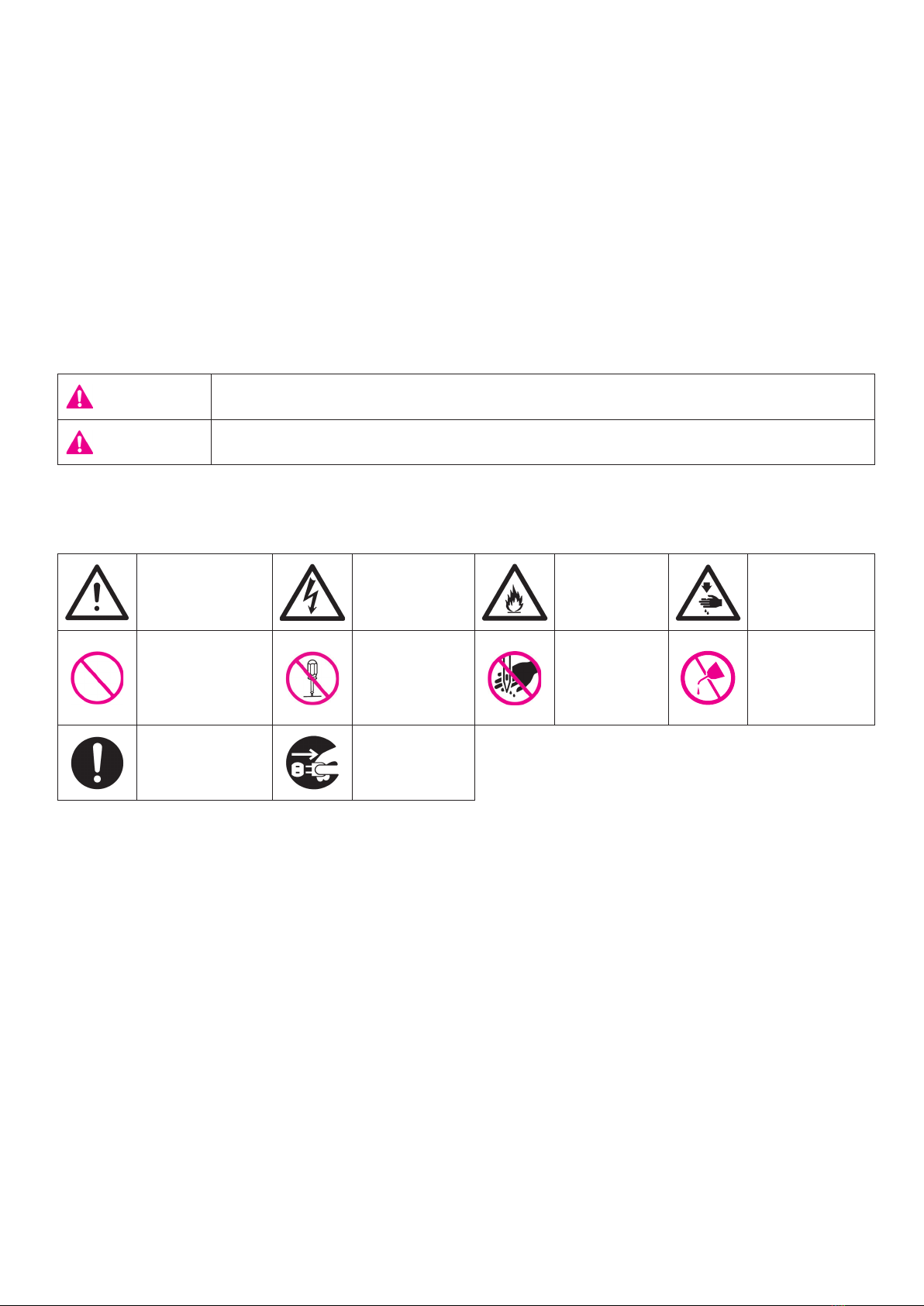
“DANGER ____ To reduce the risk of electric shock:”
1. The appliance should never be left unattended when plugged in.
2.
Always unplug this appliance from the electric outlet immediately after using and before cleaning.
“WARNING ____ To reduce the risk of burns, re, electric shock, or injury to persons:”
1. Do not use the appliance as a toy. Caution is advised when the appliance is used by children, or
near children. This sewing machine can be used by children aged from 8 years and above and
persons with reduced physical, sensory or mental capabilities or lack of experience and knowl-
edge if they have been given supervision or instruction concerning use of the sewing machine
in a safe way and understand the hazards involved. Children shall not play with the sewing
machine. Cleaning and user maintenance shall not be made by children without supervision.
2. Use this appliance only for its intended use as described in this manual. Use only attachments
recommended by the manufacturer as contained in this manual.
3. Never operate this appliance if it has a damaged cord or plug, if it is not working properly, if it
has been dropped or damaged, or dropped into water. Return the appliance to the nearest au-
thorized dealer or service center for examination, repair, electrical or mechanical adjustment.
4. Never operate the appliance with any air openings blocked. Keep ventilation openings of the
sewing machine and foot control free from the accumulation of lint, dust, and loose cloth.
5.
Keep ngers away from all moving parts. Special care is required around the sewing machine needle.
6. Always use the proper stitch plate. The wrong plate can cause the needle to break.
7. Do not use bent needles.
8. Do not pull or push fabric while stitching. It may deect the needle causing it to break.
9.
Do not carry out sewing with a marking pin stuck in the material since doing so can cause knife/needle
breakage. In addition, do not attempt to cut anything other than fabric and thread with the upper/lower knives.
10. Switch the sewing machine o “O” when making any adjustments in the needle area, such as
threading needle, changing needle, threading looper, or changing presser foot and the like.
11. Always unplug the machine from the electrical outlet when removing covers, when covers are
opened to thread the loopers, when lubricating or when making any other user servicing adjust-
ments mentioned in the instruction manual.
12. Never drop or insert any object into any opening.
13. Do not use outdoors.
14.
Do not operate where aerosol (spray) products are being used or where oxygen is being administered.
15. To disconnect, turn all controls to the o “O” position, then remove plug from outlet.
16. Do not unplug by pulling on cord. To unplug, grasp the plug, not the cord.
17. Basically, the machine should be disconnected from the electricity supply when not in use.
18. If the supply cord is damaged, it must be replaced by the manufacturer, its service agent or sim-
ilarly qualied persons in order to avoid a hazard.
19. (Except USA/Canada) This machine is provided with double insulation.
Use only identical replacement parts. See instructions for servicing Double-Insulated machine.
“SERVICING DOUBLE-INSULATED PRODUCTS
(Except USA / Canada)”
In a double-insulated product, two systems of insulation are provided instead of grounding. No
grounding means is provided on a double-insulated product nor should a means for grounding be
added to the product. Servicing a double-insulated product requires extreme care and knowledge
of the system and should only be done by qualied service personnel. Replacement parts for a
double-insulated product must be identical to those parts in the product. A double-insulated product
is marked with the words DOUBLE INSULATION or DOUBLE INSULATED.
The symbol may also be marked on the product.
“SAVE THESE INSTRUCTIONS”
“This overlock sewing machine is intended for household use only.”
1

Danger warn-
ing which is not
specied
There is a risk
of electrical
shock
There is a
risk of re
There is a risk
of injury to
hands, etc.
Prohibited mat-
ter which is not
specied
Disassembly/
alteration is
prohibited
Do not place
ngers
under the
needle
Do not pour
oil, etc.
Generally re-
quired behavior
Disconnect
the power
plug
Congratulations on your purchase of a JUKI sewing machine.
Please be sure to read safety precautions in “To use the sewing machine safely” in the Instruction
Manual before use to fully understand the functions and operating procedures of the sewing
machine so as to use the sewing machine for a long time.
After you have read the Instruction Manual, please be sure to keep it together with the warranty so
that you can read it whenever necessary.
To use the sewing machine safely
Marks and pictographs included in the Instruction Manual and shown on the sewing machine are
used so as to ensure safe operation of the sewing machine and to prevent possible risk of injury to
the user and other people.
Warning marks are used for dierent purposes as described below.
WARNING Indicates that there is a possible risk of death or serious injury if this mark is ignored and the sewing machine
is used in a wrong manner.
CAUTION
Indicates the operation, etc. which can cause a possible risk of personal injury and/or physical damage if this mark
is ignored and the sewing machine is used in a wrong manner.
Pictographs mean the following:
2

● Do not wipe the sewing machine with solvent
such as thinner.
When the sewing
machine is soiled, put a
small quantity of neutral
detergent on a piece of
soft cloth and carefully
wipe o the sewing
machine with it.
● Be sure to use the sewing machine in the
temperature range from 5ºC to 40ºC.
If the temperature is excessively low, the
machine can fail to operate normally.
WARNING
For the combination of the material and the thread and needle, in particular, refer to the explanation
table in “Replacement of the needle”.
If the needle or thread does not match the material used such as in the case that an extra heavy-
weight material (e.g., denim) is sewn with a thin needle (#11 or higher), the needle can break result-
ing in an unexpected personal injury.
Other precautions
● Do not put the sewing machine under the
direct sunlight or in a humid place.
Be aware that the following state can take place since the sewing machine incorporates semi-con-
ductor electronic parts and precise electronic circuits.
* The operating temperature of the sewing machine is between 5ºC and 40ºC. Do not use the
sewing machine under the direct sunlight, near the burning things such as a stove and candle, or
in a humid place. By so doing, the temperature in the interior portion of the sewing machine can
rise or the coating of the power cord can melt, causing re or electrical shock.
LED light
・
Rated Voltage: 9V
・
Maximum power consumption: 1.3W
3

Safety instructions ········································1-3
Contents······················································· 4
Details of the machine···································5-6
• Accessories················································ 6
Assembling thread stand ·······························7-8
Preparing the machine ···································· 9
• Attaching the foot control······························· 9
• On/O of the power/light switch ······················ 9
Operation and function
・
Handwheel (Pulley) ·····································10
・
Opening and closing the looper cover ·············10
・
Opening and closing the cloth plate ················10
・
Presser foot lifter ········································ 11
・
Changing the presser foot····························· 11
・
Releasing the upper knife ·····························12
・
Lower knife adjusting knob····························13
・
Stitch length adjusting knob ··························13
・
Dierential feed adjusting knob ······················14
・
Overlocking width selection knob ···················14
・
Presser foot pressure adjusting screw ·············15
・
Changing the needles ··································15
Stitch chart···················································16
Threading
・
Preparation················································17
Threading: 5-thread overlock
(chainstitch & 3-thread overlock) ················· 18-22
Chainstitch & wide 3-thread overlock·················23
2-thread chainstitch ·······································24
Threading: 4-thread overlock ······················ 25-28
3-thread overlocking ······································29
・
4 mm wide 3-thread overlocking·····················29
・
6 mm wide 3-thread overlocking·····················29
How to use the 2/3 thread converter··················30
Trial sewing··················································31
・
After threading, make a trial sewing ················31
Contents
Adjusting the thread tension ······················· 31-32
Sewing in tape··············································33
Roll hemming ···············································34
Dierential feed·············································35
Gathering ····················································36
Unpicking seams···········································36
Thread breakage during sewing ·······················37
Securing seams ············································37
Maintenance
・
Replacing the upper knife ·····························38
・
Cleaning and lubrication ·······························38
Troubles and corrective measures ····················39
Specications ···············································39
Optional Accessories ·····································40
4

View with looper cover open
Details of the machine
CAUTION :
Be sure to turn o the power switch before opening
the looper cover.
1. Looper cover
2. Looper cover opening handle
3. Chip guard cover
4. Cloth plate
5. Throat plate
6. Presser foot
7. Lower looper thread tension dial
8. Upper looper thread tension dial
9. Right-hand needle thread tension dial
10. Left-hand needle thread tension dial
11. Thread take-up cover
12. Thread guide plate
13. Presser foot adjusting screw
14. LED light
15. Power/light switch
16. Handwheel (pulley)
17. Machine socket
18. Spool holders
19. Anti-vibration cone
20. Spool pin
21. Retractable support rod
22. Thread guide
23. Open thread guide
24. Presser foot lifter
25. Anti-vibration pad
26. Stitch length adjusting knob
27. Differential feed adjusting knob
1. Upper looper
2. Upper knife
3. Lower knife
4. Overlock width selection knob
5. Lower looper
6. Lower knife setscrew
7. Lower looper threader
8. Chainstitch looper
9. Upper looper release
1
2
3
4
6
7
5
8
9
21
3
10
9
1
11
12
13
14
3
2
4
5
6
7
8
15
2
5

Accessories
View with cloth plate open
Details of the machine
1. Lower knife adjusting knob
2. Stitch length adjusting knob
3. Chainstitch looper threader
1. Foot control
2. Lower knife blade
3. 2/3 thread converter
4. Nets
5. Spool caps
6. Tweezers
7. Cleaning brush
8. Needle threader
9. Needles in the needle box
10. Small screwdriver
11. Large screwdriver
12. Oiler
13. Accessory bag
14. Dust cover
15. Chainstitch seam guide plate
1
2
3
4
6
7
5
8
9
21
3
10
9
1
11
12
13
14
3
2
4
5
6
7
8
15
2
1
2
3
4
6
7
5
8
9
21
3
10
9
1
11
12
13
14
3
2
4
5
6
7
8
15
2
6

Assembling thread stand
Raise the support rod fully
Turn the thread stand until it engages the positioning stopper (A)
with a click.
Put the thread guide on the support rod.
Insert the thread guide into the tip of the support rod so that the
arrow in the thread guide points toward you.
Attaching the spool holders
Attach the separately packed spool holder (equipped with two spool
holders pins) to the fixed spool holder, by pushing until it snaps in
place.
For small house-use spools
A
3
A
3
A
3
2
1
3
4
7

Assembling thread stand
For large spools
For spools of large inside diameter, position the anti-vibration come
upside down.
2
1
3
4
For home sewing spools
When using home sewing spools, remove the anti-vibration cones.
Place a spool on the spool holder with its notch downward and push
the spool caps on with the rounded outside edge at the bottom.
2
1
3
4
Notch
8

Preparing the machine
Attaching the foot control
CAUTION :
Be sure to turn OFF the power switch before plugging/un-
plugging the controller.
1. Plug foot control into machine-socket-inlet.
2. Plug foot control into socket-outlet.
3. Lay your foot on the foot control.
Press firmly on the foot control to increase sewing speed.
Press lighty on the foot control to decrease sewing speed.
2
1
3
5
1. Plug foot control into machine-socket-inlet.
2. Plug foot control into socket-outlet.
Polarized
socket-outlet
WARNING (For U.S.A., Canada only)
This appliance has a polarized plug (one blade
wider than the other). To reduce the risk of
electric shock, this plug is intended to fit in a
polarized socket-outlet only one way.
If the plug does not fit fully in the polarized
socket-outlet, reverse the plug. If it still does
not fit, contact a qualified electrician to install
the proper polarized socket-outlet.
Do not modify the plug in any way.
When you do not use the sewing machine:
1. Turn the power/light switch off. (Position A)
2. Pull the machine plug out from the socket-outlet.
3. Never place anything on the foot control.
OFF
Machine-ON
Light-OFF
Machine-ON
Light-ON
A
B
C
Polarized power supply socket
Polarized For UL, CSA
A
B
C
On/O of the power/light switch
A Position turns the power switch off.
B Position turns the power switch on, and sewing operation is
performable. The sewing light remains off.
C Position turns on both the power switch and sewing light.
CAUTION :
Perform these following steps when you are not using your
sewing machine.
1. Turn the power/light switch off. (Press side).
2. Be sure to remove the power plug from the wall outlet.
3. Do not place a thing on the foot controller.
9

Operation and function
Handwheel (Pulley)
The handwheel turns toward you.
・ Upon completion of threading, at sewing start or sewing end, be
sure to turn the handwheel toward you.
Opening and closing the looper cover
Opening: To open the looper cover, pull the looper cover opening
handle to the right, and tilt the looper cover toward you.
Closing: To close the looper cover, push up the looper cover, press
it lightly to the right. The looper cover closes automatical-
ly.
Removing and attaching the chip guard cover
Removing the chip guard cover:
To remove the chip guard cover, open the looper cover and draw
the chip guard cover toward you until it comes off.
Attaching the chip guard cover:
To install the chip guard cover, open the looper cover and attach
the chip guard cover in position while fitting its top end in the slit
on the looper cover.
Caution Zur Beachtung
Attention
Precaucion
6
Caution Zur Beachtung
Attention
Precaucion
6
Caution Zur Beachtung
Attention
Precaucion
6
Opening and closing the cloth plate
Opening: Press the cloth plate toward the outside.
Closing: Push the cloth plate toward the sewing machine.
CAUTION :
For safety, the power is automatically cut o when you
openthe looper cover or the cloth plate or remove the chip
guard cover.
Caution Zur Beachtung
Attention
Precaucion
6
10

Operation and function
Presser foot lifter (To raise the presser foot by the presser foot
lifter)
A : For regular sewing operation (sewing a medium-weight materi-
al), raise the presser foot to position (A) illustrated in the figure.
B : When you sew a heavy-weight material, raise the presser foot
to position (B) illustrated in the figure, to provide more space
between presser foot and throat plate.
Changing the presser foot
Switch the machine o (power switch”O”)
WARNING :
When using the extra lift (B), do not run the machine or turn
the handwheel.
1. Raise the presser foot.
2. Turn the handwheel until the needle is fully raised.
3. Press point (C) ilustrated in the figure, and the presser foot
will be released.
4. To release the presser foot, raise the presser foot lifting lever
to its highest position (B). Then you can release the presser
foot easily.
5. To attach the presser foot, place it so that the presser foot
pin (D) comes exactly under the groove in the holder. Lower
the presser foot lifting lever and the presser foot will engage
automatically.
A
C
D
B
Caution Zur Beachtung
Attention
Precaucion
7
C
D
8
A
B
1. Turn the handwheel until the upper knife is fully raised. Open
the looper cover.
2. Press the part indicated as (A) in the figure toward the right
until it will go no further.
3. Keep pressing (A) and turn the knob on the right side in the
direction of the arrow.
4. Turn the knob until the knife reaches position (B), and snaps
into locked position.
Releasing the upper knife
Switch the machine o (power switch”O”)
11

Operation and function
9
Operation and function/Operación y función
Betrieb und Funktion/Opération et fonction
Make sure to set the upper knife at a prescribed position.
Asegúrese de fijar la cuchilla superior en la posición prescrita.
Stellen Sie das Obermesser unbedingt auf die vorgeschriebene Position ein.
Régler le couteau supérieur sur la position prescrite.
Caution, Raising and lowering the upper knife.
Precaución, Elevación y descenso de la cuchilla superior.
Vorsicht, Anheben und Absenken des Obermessers.
Attention, Relevage et abaissement du couteau supérieur.
1. Raising the upper knife. Turn the knob clockwise until the knife reaches a prescribed position.
Don’t set the knife on the halfway position.
2. Lowering the upper knife. Turn the knob counterclockwise until the knife reaches a prescribed
position. Don’t set the knife on the halfway position.
1. Elevación de la cuchilla superior. Gire la perilla en el sentido de las manecillas del reloj hasta
que la cuchilla alcance la posición prescrita.
No fije la cuchilla en ninguna otra posición.
2. Descenso de la cuchilla superior. Gire la perilla en el sentido contrario a las manecillas del
reloj hasta que la cuchilla alcance la posición prescrita.
No fije la cuchilla en ninguna otra posición.
1. Anheben des Obermessers. Drehen Sie den Knopf im Uhrzeigersinn, bis das Messer die
vorgeschriebene Position erreicht.
Stellen Sie das Messer nicht auf eine Zwischenstellung.
2. Absenken des Obermessers. Drehen Sie den Knopf entgegen dem Uhrzeigersinn, bis das
Messer die vorgeschriebene Position erreicht.
Stellen Sie das Messer nicht auf eine Zwischenstellung.
1. Relevage du couteau supérieur. Tourner le bouton dans le sens des aiguilles d’une montre
jusqu’à ce que le bouton se trouve sur la position prescrite. Ne pas régler le couteau sur une
position intermédiaire.
2. Abaissement du couteau supérieur. Tourner le bouton dans le sens inverse des aiguilles d’une
montre jusqu’à ce que le bouton se trouve sur la position prescrite. Ne pas régler le couteau
sur une position intermédiaire.
Caution, Raising and lowering the upper knife.
1. Raising the upper knife. Turn the knob clockwise until the knife
reaches a prescribed position. Don’t set the knife on the halfway
position.
2. Lowering the upper knife. Turn the knob counterclockwise until
the knife reaches a prescribed position. Don’t set the knife on
the halfway position.
Make sure to set the upper knife at a prescribed position.
12

Operation and function
10
C
D
EF
A B
11
Lower knife adjusting knob (adjusting the lower knife position for
cutting width)
Turn the lower knife adjusting knob by pressing part (C) in the figure.
(E): If the edge of the sewing material curls, set the lower knife ad-
justing knob (D) to a lower number setting.
(F): If the thread is loosely looping on the outer edge of the material,
set the lower knife adjusting knob, to a larger number setting.
Switch the machine o (power switch”O”)
Stitch length adjusting knob (to adjust the stitch length)
Stitch length is adjustable within the range from 1 to 4.
To adjust the stitch length, turn the stitch length adjusting knob and
move the knob upwards or downwards
・
For normal overlocking stitches set the stitch length adjusting knob
at 2 to 3.
13

Operation and function
Dierential feed adjusting knob (To adjust the feeding for
gathering or stretching)
To adjust feeding for gathering or stretching, turn the differential
feed adjusting knob upward or downward. The differential feed
prevents fluting or waving in seams in stretchy materials by differen-
tiating the feed of the front feed dog (A) and rear feed dog (B). For
more application, information, see page 36.
A B
11
Overlocking width selection knob (For overlocking or roll
hemming)
・
Turn the handwheel until the needles are fully raised
A For overlocking
Push the overlocking width selection knob should align with the
rear red marking on the throat plate.
B For roll hemming
1. Pull the overlocking width selection knob should align with the
front red marking on the throat plate.
2. Set the lower knife adjusting knob at “1 ~ 2”.
Switch the machine o (power switch”O”)
A
B
C
12
Be sure to turn power switch OFF.
A
B
C
12
Be sure to turn power switch OFF.
14

Operation and function
Presser foot pressure adjusting screw
Pressure of the presser foot has been factory-adjusted properly.
Therefore you do not need to adjust it except when sewing a special
material.
・
To increase the pressure of the presser foot : For heavy-weight
materials such as denim, tweed, or heavy linen.
・
To decrease the pressure of the presser foot : For light-weight
materials such as georgette, lace, or tricot.
(C): Standard posilion : The lower part of control cap aligns with the
upper tace of cover.
A
B
C
12
Be sure to turn power switch OFF.
B
A
C
D
13
B
A
C
D
13
B
A
C
D
13
Flat side of a needle
Changing the needles
・
Using the needle inserter (D) on the cleaning brush will help replace
the needle easily.
1. Turn the handwheel until the needles are fully raised.
2. Before changing the needles, lower or remove the presser foot.
3. Using a small screwdriver, loosen the needle setscrew and remove
the needle.
4. Insert the needle with the flat side away from you into the needle
clamp, making sure it is inserted as far up as possible. Tighten the
needle clamp setscrews securely.
Needles used Types of needles Size
A Right-hand needle Household type
130/705H
No. 75/11
or 90/14
B Left-hand needle
C Chainstitch needle
* Needle with No. 75/11 is intended for light-weight materials and general
fabric. Needle with No. 90/14 is intended for heavy-weight materials.
NOTE : To insert the needle into the needle clamp, loosen the needle clamp
screw until flush with the clamp and insret the needle as far as possi-
ble into the clamp.
Switch the machine o (power switch”O”)
15

Changing the needles
Stitch Chart
Stitch Stitch width Tension settings Basic settings
5 thread overlock (chainstitch
and narrow 3 thread overlock)
14
3 - 5 mm, right needle
Chainstitch needle
10 mm
Right needle green 3 - 5
Upper looper blue 3 - 5
Lower looper red 3 - 5
Chainstitch needle purple 3 - 4
Chainstitch looper purple
Stitch length: 2, 5
Cutting width: 2
Differential: N
5 thread overlock (chainstitch
and wide 3 thread overlock)
14
5- 7 mm, left needle
Chainstitch needle
10 mm
Left needle brown 6 - 7
Upper looper blue 3 - 5
Lower looper red 3 - 5
Chainstitch needle purple 3 - 4
Chainstitch looper purple -
Stitch length: 2, 5
Cutting width: 2
Differential: N
2 thread chainstitch
14
--- Chainstitch needle purple 3 - 4
Chainstitch looper purple -
Stitch length 2, 5
Knife: Raised, chainstitch seam
guide plate used
Differential:
N -2 (knits), N - 0,7 (wovens)
4 thread overlock, with integrat-
ed safety seam
14
5 - 7 mm, right and left nee-
dles
Left needle yellow 3 - 5
Right needle green 3 - 5
Upper looper blue 3 - 5
Lower looper red 3 - 5
Stitch length: 2, 5
Cutting width: 2
Differential:
N - 2 (knits),
N - 0,7 (wovens)
3 thread overlock
14
3 - 5 mm, right needle
5- 7 mm, left needle
Left needle yellow 3 - 5
Right needle green 3 - 5
Upper looper blue 3 - 5
Lower looper red 3 - 5
Stitch length: 2, 5
Cutting width: 2
Differential:
N - 1,5 (knits),
N - 0,7 (wovens)
3 thread flatlock
14
3 - 5 mm, right needle
5- 7 mm, left needle
Left needle yellow 1 - 2
Right needle green 1 - 2
Upper looper blue 3 - 5
Lower looper red 7 - 9
Stitch length: min. 2, 5
Cutting width: 2
Differential: N
3 thread roll hem
14
2 mm, right needle Right needle green 4 - 6
Upper looper blue 3 - 5
Lower looper red 5 - 7
Stitch length: 1 - 1.8
Cutting width: 1 - 1.5
Differential: N - 0.7
Stitch lever: roll hem
3 thread narrow seam
14
2 mm, right needle Right needle green 4 - 6
Upper looper blue 5 - 7
Lower looper red 3 - 5
Stitch length: 1 - 1.8
Cutting width: 1 - 1.5
Differential: N - 0.7
Stitch lever: roll hem
2 thread wrapped overlock
14
3 - 5 mm, right needle
5- 7 mm, left needle
Left needle yellow 3 - 5
Right needle green 3 - 5
Lower looper red 2 - 4
Stitch length: 2.5
Cutting width: 2
Differential:
N - 1,5 (knits),
N - 0,7 (wovens)
2 thread flatlock
14
3 - 5 mm, right needle
5- 7 mm, left needle
Left needle yellow 1 - 2
Right needle green 1 - 2
Lower looper red 4 - 6
Stitch length: min. 2, 5
Cutting width: 2
Differential: N
2 thread roll hem
14
1,5 mm, right needle Right needle green 3 - 5
Lower looper red 2 - 4
Stitch length: 1 - 1.8
Cutting width: 1 - 1.5
Differential: N - 0.7
Stitch lever: roll hem
16

Threading
Preparation
1. Retractable support rod with thread guide must be fully raised.
2. Open the looper cover and cloth plate.
3. Turn the handwheel toward you until the needles are fully raised.
4. Release the upper knife.
Thread the machine carefully and in the correct sequence.
This is important for making beautiful seams.
Thread the machine carefully and in the correct sequence.
Invaluable threading aids simplify threading:
・
colored threading illustration
・
color coded thread path on the machine.
・
threading accessories.
Switch the machine o (power switch”O”)
Thread guide plate
Slide thread into the two slits to form an S-loop.
Threading the tension dials
To lay the thread correctly between the tension discs, pull the thread
lightly with both hands.
10
11
12
13
12
3
4
5
6
8
7
9
11 10
14 13
12
18
Needle threader
Insert the needle threader through the back of the needle eye or the
looper eye then thread the needle threader. Pull the needle threader
back until it pulls through the eyelet.
10
11
12
13
12
3
4
5
6
8
7
9
11 10
14 13
12
18
10
11
12
13
12
3
4
5
6
8
7
9
11 10
14 13
12
18
17

Threading: 5-thread overlock (chainstich & 3-thread overlock)
10
11
12
13
12
3
4
5
6
8
7
9
11 10
14 13
12
19
10
11
12
13
12
3
4
5
6
8
7
9
11 10
14 13
12
19
1. Upper looper thread (Blue)
Place the spool on the spool pin right under blue marking on the
retractable support rod thread guide.
(1,2) Bring thread up from the rear of the retractable support rod
thread guide with blue marking, to the front of it.
(3,4) Pass the thread through the thread guide plate. Looping as
shown.
(5) Snap the thread into the thread guide.
(6) Lay the thread between the thread tension dial discs.
(7,8,9,10,11,12) Thread the thread guides.
(13) Turn the handwheel until the upper looper is fully raised.
Thread upper looper eye.
(14) Pull about 10 cm of the thread out.
Place the thread under the presser foot, and pull the thread
from behind the presser foot.
Use a net for a hard twisted thread.
When a thread coils around the thread guide due to its hard twist,
cover the spools of upper looper and lower looper with nets.
18

Threading: 5-thread overlock (chainstich & 3-thread overlock)
2. Lower looper thread (Red)
Place the spool on the spool pin right under red marking on the
retractable support rod thread guide.
(1) Bring thread up from the rear of the retractable support rod
thread guide.
(2,3) Pass the thread through the thread guide plate. Snapping into
place.
(4) Snap the thread in to the thread guide.
(5) Thread the thread tension dial.
(6,7,8,9) Thread the thread guides.
(10) Raise the needles fully and press the lever of the threading
device down.
Thread upper looper eye.
(11,12)
Thread the guide and then the slit on the device. Holding the
thread loosely with the left hand, turn the hand wheel until
upper and lower loopers just cross. The threading device will
automatically return to the normal position.
(13) Thread the lower looper eye and place thread under the press-
er foot.
* If rethreading the lower looper thread, cut the needle threads
at the needle. And rethread needle threads. Thread the lower
looper and then the needles.
19
Table of contents
Other JUKI Sewing Machine manuals

JUKI
JUKI JTR-MS1190/TA-STS User manual

JUKI
JUKI DLN-415 User manual

JUKI
JUKI APW-896/IP-420 User manual

JUKI
JUKI SC-510 User manual

JUKI
JUKI MO-1000 User manual

JUKI
JUKI MO-50e User manual

JUKI
JUKI AMS-210E/IP-410 User manual

JUKI
JUKI IP-100 Quick start guide

JUKI
JUKI HZL - 355Z Series User manual

JUKI
JUKI MOL-254 User manual

JUKI
JUKI MF-7200D User manual

JUKI
JUKI SC-956A User manual

JUKI
JUKI DU-1481 Series User manual

JUKI
JUKI MO-114D User manual

JUKI
JUKI MF-7200D User manual

JUKI
JUKI CP-160 User manual

JUKI
JUKI MF-7900 Series Quick start guide

JUKI
JUKI MCS-1800 User manual

JUKI
JUKI AK-159 User manual

JUKI
JUKI LU2-4652-B1T User manual