jurop HELIX 140 Setup guide

T
TR
RA
AN
NS
SL
LA
AT
TI
IO
ON
NO
OF
FO
OR
RI
IG
GI
IN
NA
AL
LI
IN
NS
ST
TR
RU
UC
CT
TI
IO
ON
NS
S
S
SU
UP
PP
PL
LE
EM
ME
EN
NT
TT
TO
OT
TH
HE
E
I
IN
NS
ST
TA
AL
LL
LA
AT
TI
IO
ON
N,
,U
US
SE
EA
AN
ND
D
M
MA
AI
IN
NT
TE
EN
NA
AN
NC
CE
EM
MA
AN
NU
UA
AL
L
EN HELIX SYSTEM
Rev. 00
09-11-2023

REV. 0
0
09-11-
2023
HELIX SYSTEM INSTALLATION, USE AND MAINTENANCE MANUAL
2 / 32
Jurop SpA
Via Crosera n° 50
33082 Azzano Decimo, PN (Italia)
TEL. +39 0434 636811 FAX. +39 0434 636812
http://www.jurop.it
e-mail: [email protected]
2023 – Jurop – Azzano Decimo (PN)
Reproduction, electronic storage and dissemination, even partial, are wholly prohibited.
Jurop reserves the right to modify the products described in this manual without prior notice.
Any product names mentioned herein are the trademarks of their respective owners.

REV. 00
09-11-2023 HELIX SYSTEM INSTALLATION, USE AND MAINTENANCE MANUAL
3 / 32
Jurop SpA
Via Crosera n° 50
33082 Azzano Decimo, PN (Italia)
TEL. +39 0434 636811 FAX. +39 0434 636812
http://www.jurop.it
e-mail: [email protected]
Contents
1. General warnings page 4
1.1 Introduction 4
1.2 Request for spare parts 5
1.3 Warranty terms and conditions 5
2. Technical data page 5
2.1 Dimensions HELIX 140-180-220 SYSTEM 6
2.2 Dimensions HELIX 300 SYSTEM 6
2.3 Dimensions HELIX 300 HYD SYSTEM 7
2.4 Performance 7
2.5 Hydraulic motor power supply 8
2.6 Noise 8
3. Safety and accident prevention page 8
3.1 General recommendations 8
3.2 Intended use 9
4. Installation page 9
4.1 Inspection on receipt 9
4.2 Warehouse storage 9
4.3 Handling 9
4.4 Example of unit installation on vehicle 10
4.5 Assembly - Power transmission 11
4.6 Start-up and preventive checks 13
5. Maintenance page 13
5.1 HELIX compressor / vacuum pump 14
5.2 Suction unit 16
5.3 Silencers 17
5.4 Air filter 18
5.5 Cyclone purifier 18
5.6 Gearbox 21
5.7 Vacuum gauge and remote thermometer 21
SPARE PARTS SHEET – HELIX 140-180-220 SYSTEM 23
SPARE PARTS SHEET – HELIX 300 SYSTEM 26

REV. 0
0
09-11-
2023
HELIX SYSTEM INSTALLATION, USE AND MAINTENANCE MANUAL
4 / 32
Jurop SpA
Via Crosera n° 50
33082 Azzano Decimo, PN (Italia)
TEL. +39 0434 636811 FAX. +39 0434 636812
http://www.jurop.it
e-mail: [email protected]
1.1. Introduction
This manual provides indications regarding the use and maintenance of the HELIX SYSTEM unit, as well as some warnings for the operator
regarding basic safety regulations.
Knowing the information below is essential to use the unit properly.
Following the instructions below contributes to limiting unit repair expenses by extending its duration, as well as preventing hazardous situations,
thereby increasing its reliability.
In case the hydraulic motor is present, refer to the specific manufacturer's manual.
It is essential to:
Read and apply the instructions before starting up the unit.
Keep the manual in a place known to all users.
Below is a brief description of the symbols used in this manual.
Safety regulations, non-compliance with which may result in injuries to operators and significant damage to the unit or system
Safety regulations, non-compliance with which may damage the unit or system
Suggestions for using the unit respecting the environment
Useful advice to simplify the use and maintenance of the unit
The graphic representations and photographs contained in this manual are there to illustrate the product in the parts that make it up and in
specific operating phases. Though the model shown in the manual may differ from the one purchased, the operating principle at the base of the
illustrated operating phase is the same.
Each HELIX SYSTEM unit has an identification plate, in which the following are detectable: code, model, serial number (the same as the
vacuum pump/compressor) and year of construction.
Fig. 1.1
Each HELIX vacuum pump/compressor can only be installed if it has an identification plate.
1. General warnings

REV. 00
09-11-2023 HELIX SYSTEM INSTALLATION, USE AND MAINTENANCE MANUAL
5 / 32
Jurop SpA
Via Crosera n° 50
33082 Azzano Decimo, PN (Italia)
TEL. +39 0434 636811 FAX. +39 0434 636812
http://www.jurop.it
e-mail: [email protected]
PRESSURE GAUGES
& REMOTE THERMOMETER
3 SHAFT
GEARBOX DRIVE
2-WAY VALVE
SET-UP
ADJUSTABLE
CONVEYOR
FLUSHING KIT
CUSTOM SILENCERS
AIR FILTER
DUAL STAGE CYCLONE
SHUT-OFF
HELIX BLOWER
1.2. Request for spare parts
Use only genuine spare parts for maintenance and repairs.
To order spare parts, provide the following details.
EXAMPLE:
a) Unit type HELIX SYSTEM 300
b) Serial number (see plate): J90001
c) Name (see list of spare parts): CYCLONE PURIFIER
d) Quantity (see spare parts list): 1
e) Code (see list of spare parts): 14450 065 E0
1.3. Warranty terms and conditions
Compliance with the installation, use and maintenance instructions provided by this manual is a requirement for recognition of the warranty on
defective parts.
HELIX SYSTEM is a module consisting of a vacuum pump/compressor with a three-axis gearbox to be connected to the power transmission of
the equipment on which it is mounted. The version with hydraulic motor has no gearbox.
HELIX SYSTEM is equipped with:
Gearbox or hydraulic motor
Direct drive - NO coupling
Vacuum gauge and remote thermometer
Cyclone purifier
Injection/discharge silencers
Air filter
Flushing kit
Swiveling conveyors
2-way valve set-up
Oil level sensors
Fig. 2.1
2. Technical data

REV. 0
0
09-11-
2023
HELIX SYSTEM INSTALLATION, USE AND MAINTENANCE MANUAL
6 / 32
Jurop SpA
Via Crosera n° 50
33082 Azzano Decimo, PN (Italia)
TEL. +39 0434 636811 FAX. +39 0434 636812
http://www.jurop.it
e-mail: [email protected]
I
J
M
N
D
B
L
V
F
G
C
A
S
R
T
W
Q
O P
U
K
H
E
G
F
D
CX
H
I
J
B
V W
L
K
T
R
S
U
O P
Q
M
N
A
E
2.1. Dimensions HELIX 140-180-220 SYSTEM
A B C D E F G H I J K L
H.S. 140 in 39.5 49 28 31 10 8.7 5.4 3.1 6.4 9.7 Ø 2.8 Ø 5
mm 1004 1234 702 784 255 220 137 80 163 246 Ø 69.8 Ø 116
H.S. 180 in 40.5 49 28 31 11 9.6 6.4 3.1 6.4 9.7 Ø 2.8 Ø 5
mm 1029 1234 702 784 280 245 162 80 163 246 Ø 69.8 Ø 116
H.S. 220 in 42 49 28 31 12 10.6 7.4 3.1 6.4 9.7 Ø 2.8 Ø 5
mm 1054 1234 702 784 305 270 187 80 163 246 Ø 69.8 Ø 116
M N O P Q R S T U V W X
H.S. 140 in Ø 3.8 Ø 0.4 7.7 7.7 8.1 Ø 1.8 1.9 0.6 0.4 16.9 Ø 4.7 1
mm Ø 95.2 Ø 11.2 196 196 206 Ø 45 48.8 14 M10 430 Ø 120 15
H.S. 180 in Ø 3.8 Ø 0.4 7.7 7.7 8.1 Ø 1.8 1.9 0.6 0.4 16.9 Ø 4.7 1
mm Ø 95.2 Ø 11.2 196 196 206 Ø 45 48.8 14 M10 430 Ø 120 15
H.S. 220 in Ø 3.8 Ø 0.4 7.7 7.7 8.1 Ø 1.8 1.9 0.6 0.4 16.9 Ø 4.7 1
mm Ø 95.2 Ø 11.2 196 196 206 Ø 45 48.8 14 M10 430 Ø 120 15
2.2. Dimensions HELIX 300 SYSTEM

REV. 00
09-11-2023 HELIX SYSTEM INSTALLATION, USE AND MAINTENANCE MANUAL
7 / 32
Jurop SpA
Via Crosera n° 50
33082 Azzano Decimo, PN (Italia)
TEL. +39 0434 636811 FAX. +39 0434 636812
http://www.jurop.it
e-mail: [email protected]
A
D
E
G H
C
B
F
A B C D E F G H I J K L
H.S. 300 in 44 51 30 32 13.2 11.9 7.9 1.6 5.7 9.7 Ø 3 Ø 5
mm 1122 1306 769 814 336 301 201 41 146 246 Ø 70 Ø 116
M N O P Q R S T U V W
H.S. 300 in Ø 4 7/16-20 UNF 9.3 9.3 9.6 Ø 2.2 2.3 0.6 0.4 19.7 Ø 4.7
mm Ø 95 7/16-20 UNF 235 235 245 Ø 55 59.3 16 M10 500 Ø 120
2.3. Dimensions HELIX 300 SYSTEM with hydraulic motor
A B C D E F G H
HDR in 37.6 51 30 5 11.6 3.2 19.7 4.7
mm 955 1306 769 134 295 81 500 120
2.4. HELIX SYSTEM performance
The unit can be equipped with gearbox. The gearbox reduction ratio is 1:2. This means that the speed required at the gearbox input is half the
speed required by the vacuum pump.
I The rotation speed values, found in the following table, are those of the required speed at the gearbox input. This
does not apply to units with hydraulic motor.
HELIX SYSTEM 140 180 220 300
Free inlet air flow rate (at rpm max) 500 cfm (14200 l/min) 642 cfm (18200 l/min) 755 cfm (21350 l/min) 1090 cfm (21350 l/min)
Max. rotation speed (with gearbox) 2000 rpm 2000 rpm 2000 rpm 1500 rpm
Recommended rotation speed (with gearbox) 1800 rpm 1800 rpm 1800 rpm 1400 rpm
Recommended rotation speed (with HDR motor) - - - 2900 rpm
Maximum vacuum 27,3 Hg (91 %) 27,3 Hg (91 %) 27,8 Hg (93 %) 27,8 Hg (93 %)
Maximum no-load power 32 HP (24 kW) 43,5 HP (32 kW) 47 HP (35 kW) 75 HP (56 kW)
Maximum pressure 15 psig (1 bar) 15 psig (1 bar) 15 psig (1 bar) 15 psig (1 bar)
Power at maximum pressure 37,5 HP (28 kW) 48 HP (36 kW) 58 HP (43 kW) 79 HP (59 kW)
Helix System weight with gearbox 888 Ibs (403 kg) 915 Ibs (415 kg) 944 Ibs (428 kg) 1197 Ibs (543 kg)
Helix System weight with HDR motor - - - 1127 Ibs (511 kg)
REFERENCE CONDITIONS - The data shown in the table are subject to a tolerance of +/- 5%.
Conveyed gas: air Reference temperature: 20°C(68°F) Vacuum operation: atmospheric discharge
Reference absolute pressure: 1013mbar (14.7psi) Pressure operation: atmospheric intake

REV. 0
0
09-11-
2023
HELIX SYSTEM INSTALLATION, USE AND MAINTENANCE MANUAL
8 / 32
Jurop SpA
Via Crosera n° 50
33082 Azzano Decimo, PN (Italia)
TEL. +39 0434 636811 FAX. +39 0434 636812
http://www.jurop.it
e-mail: [email protected]
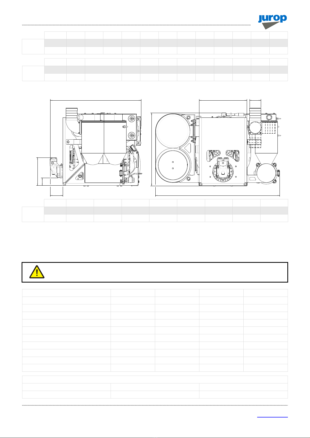
2.5. Hydraulic motor power supply
The performance data of the hydraulic motor are given in the following table.
HELIX 300 SYSTEM with hydraulic motor
Displacement 40 cc/rev Filtration class 20/18/13 (ISO 4406)
Continuous pressure 1420 bar Optimal viscosity 15-30 cSt
Max. drain line pressure 1 bar Max. viscosity 1000 cSt
Fluid HLP Max oil temperature 280 °C
1Motor in continuous service. With pump operating within the prescribed operating limits, the actual working pressure is always lower. | 2With
reference to the temperature of the oil present in the main circuit.
2.6. Noise
The sound pressure and sound power values of the pump are given inside the HELIX vacuum pump/compressor manual.
The noise value in Db varies according to the system realised, and the supply and suction pipes. Please remember to use Personal Protective
Equipment (headphones) to reduce the effect of noise.
Sound power verification cannot be performed without completion of the vacuum line system. This verification is the responsibility of the final
installer.
Apply these prescriptions carefully.
3.1. General recommendations
When transporting the unit, fasten appropriately. Rest the unit on stable points.
Installation and maintenance must be done with the unit stopped, power transmission disengaged and by skilled personnel.
Work on the unit dressed appropriately (avoid ties, wide sleeves, necklaces, etc.) and using suitable protective equipment (gloves, goggles,
shoes, etc.).
Before any maintenance operations, stop the unit and bring the system back to atmospheric pressure.
To intervene on the unit, all the components of the unit must be stopped and cold.
To prevent errors and hazardous situations, establish what each operator is responsible for in the different maintenance operations.
Final manufacturer must make the transmission inaccessible by means of a fixed guard or interlocked movable guard. Do not start the unit up
without the safety devices required for the transmission parts. Replace damaged protections.
Operators working in the vicinity must avoid prolonged exposure to the noise emitted by the suction equipment if they are not equipped with
suitable protection (PPE recommended: ear protectors).
The components can reach very high temperatures (over 90°C) during operation. Use all means necessary to avoid contact.
During vacuum operation, avoid accidental intake of solids: they can be projected at high speed through the discharge manifold, damaging the
silencer.
Safety valves: direct the air flow away from operators.
Do not use the unit beyond its limits of use: risk of breakage with consequences for the operators.
Do not exceed the rotation speed and maximum pressure given in the technical table in paragraph 2.4.
Based on the final use of the unit, the insertion in the housing machine and the typology of the same, the designer of the housing machine must
apply safety signals (pictograms) to warn the operator on the risk still present. These pictograms essentially refer to three categories:
3. Safety and accident prevention

REV. 00
09-11-2023 HELIX SYSTEM INSTALLATION, USE AND MAINTENANCE MANUAL
9 / 32
Jurop SpA
Via Crosera n° 50
33082 Azzano Decimo, PN (Italia)
TEL. +39 0434 636811 FAX. +39 0434 636812
http://www.jurop.it
e-mail: [email protected]
signals prescribing the use of Individual Protection Devices (IPDs) such as, in this case, the use of gloves and ear protectors;
signals indicating to pay particular attention to the dangers related to the machine’s components, such as: risk of dragging in the
transmission equipment and contact with hot surfaces;
signals indicating specific parts of the machine for an easier identification, such as: greasing points, oil tanks, etc.
3.2. Intended use
HELIX SYSTEM units are intended to be used for loading and unloading liquid material. The units are used for liquid waste transport, septic tank
cleaning and other industrial applications.
The HELIX compressor / vacuum pump is suitable for conveying pollutant-free gas such as suspended oil or water: this is enabled thanks to the
absence of contact parts and thus lubrication oil inside the compression chambers.
The installer shall use all possible means to prevent foreign objects and liquids from entering the vacuum pump/compressor.
The entry of foreign objects or liquids may damage the vacuum pump/compressor
E Avoid suctioning of toxic materials and flammable or explosive gases as the internal components can reach high temperatures.
Avoid suctioning of toxic materials and flammable or explosive gases as the internal components can reach high
temperatures.
Do not use the unit beyond its intended operating limits (see par. 2.4): risk of breakage and possible transmission damage.
4.1. Inspection on receipt
When goods arrive, make sure all items are intact: they may have been damaged during transport.
Remove the packaging by removing material that may become hazardous if vacuumed.
Make sure that the HELIX vacuum pump/compressor has the identification plate. Pumps with no plate are considered anonymous and potentially
dangerous: they must, therefore, not be used, otherwise the manufacturer cannot be held liable for any event.
4.2. Warehouse storage
If the unit is not expected to be used for a long time or in the case of intermediate storage of a non-new unit, observe the following:
Perform thorough cleaning of the unit before storage, using the flushing kit. The procedure is given in paragraph 5.1.
Store in a closed and dry place.
During storage, rotate the input shaft three or four turns every two weeks to keep the internal gears lubricated.
4.3. Handling
Verify before each move that lifting equipment is suitable for the capacity. Check the weight of the unit given within this manual.
Harness the machine with suitable straps / chains near the main body, paying attention to the position of the mass center of gravity to ensure the
load stability.
The unit is equipped with hooking devices: two sheet metal eye rings and an eyebolt (fig. 4.1).
The hooking devices are screwed into the top of the unit, at a position equidistant (approximately) from the center of gravity of the masses of the
unit, to ensure stability during handling.
The unit has no components or accessories that are potentially dangerous, or that can move during lifting, handling or tilting.
When moving, do not lift the packaging or the machine more than 50 cm from the ground. Proceed with the final lifting only near the installation
point.
4. Installation

REV. 0
0
09-11-
2023
HELIX SYSTEM INSTALLATION, USE AND MAINTENANCE MANUAL
10 / 32
Jurop SpA
Via Crosera n° 50
33082 Azzano Decimo, PN (Italia)
TEL. +39 0434 636811 FAX. +39 0434 636812
http://www.jurop.it
e-mail: [email protected]
EYEBOLT
METAL LIFTING
SUPPORTS
Fig. 4.1
Check that there is space in height to handle the module, once lifted.
Before lifting the module completely, make sure that transport stability is guaranteed.
Do not stand under the machine when it is lifted during the installation.
Before placing the module on the ground, check that:
It is level, or with a maximum permissible inclination of 3° (degrees), with respect to the horizontal surface.
There is enough space for people or any vehicles to pass, or to conduct other activities.
It is not too close to heat sources or open flames, is not on walkways.
It is stably balanced and accessible from all sides for the activities required for its operation.
4.4. Example of unit installation on vehicle
The frame of the unit lacks the drilling for vehicle installation.
Drill holes in the frame of the unit.
The unit must be connected to the frame by at least 8 M16 class 8.8 bolts, distributed over the entire area. Arrange bolts on a 4x2 matrix; when
possible, increase the number of bolts.
Use frame bolts, fine pitch screws and flanged nuts.
Fig. 4.2

REV. 00
09-11-2023 HELIX SYSTEM INSTALLATION, USE AND MAINTENANCE MANUAL
11 / 32
Jurop SpA
Via Crosera n° 50
33082 Azzano Decimo, PN (Italia)
TEL. +39 0434 636811 FAX. +39 0434 636812
http://www.jurop.it
e-mail: [email protected]
4.5. Assembly - Power transmission
For HELIX SYSTEM units, the permissible power transmissions are:
Direct transmission (e.g.: from agricultural cardan shaft)
Oil hydraulic transmission (for versions with hydraulic motor).
Protect with a fixed or interlocked guard and signal with pictograms the power transmission chosen and applied by the final installer, if there is
the possibility that the operator will come into contact during handling.
CARDAN TRANSMISSION
Use telescopic cardan shafts.
Fig. 4.3
In order to achieve uniform motion of the driven axis, the following conditions must be met (see Fig. 4.3):
Equal joint angles α and α1 of the two joints;
The inner forks of the joints must be coplanar;
Driven shaft and coplanar conductors.
It is also advisable to work with small joint angles (max 15° at 1000 rpm and max 11° at 1100 rpm) and to stop the transmission during
maneuvers in which the joints work at large angles (steering or lifting).
Respect the direction of rotation of the unit. Comply with the cardan shaft manufacturer's directions.
It is the responsibility of the final installer to provide for suitable guards, in presence of transmission shafts exposed during normal operation.
In any case, the installation, by the final installer, must meet current accident prevention regulations.
OIL HYDRAULIC TRANSMISSION
Fig. 4.4 (1) FILL BEFORE STARTING
(1)
(1)
DRAINAGE
DRAINAGE
OIL TANK
CLOCKWISE
ROTATION
COUNTERCLOCKWISE
ROTATION
OIL
LEVEL

REV. 0
0
09-11-
2023
HELIX SYSTEM INSTALLATION, USE AND MAINTENANCE MANUAL
12 / 32
Jurop SpA
Via Crosera n° 50
33082 Azzano Decimo, PN (Italia)
TEL. +39 0434 636811 FAX. +39 0434 636812
http://www.jurop.it
e-mail: [email protected]
The unit can be supplied with a hydraulic motor instead of a gearbox. Performance data are given in paragraph 2.5.
Features: fixed displacement high-pressure motor usable in open or closed circuits.
Flow rate and pressure: to be defined according to the required performance of the decompressor (operating speed and pressure).
Fluid: mineral oil for HLP DIN51524 hydraulic systems and mineral oil for HL/HM ISO6743-4 hydraulic systems.
Filtration: class 20/18/13, according to ISO 4406.
Check the circuit connections: they must be consistent with the direction of rotation of the decompressor indicated by the arrow attached to
the front flange of the pump.
Drainage: connect so that the motor never runs out of oil. Connect the drainage of each motor directly to the tank. Discharge into the tank
under the free surface or bend into a U.
DRAINAGE THREADING IN/OUT FLANGING
M18x1.5 SAE ¾” 6000psi
Fig. 4.5
Start-up: make sure the system is well cleaned and put oil into the tank and motor body (needed for lubrication of internal bearings).
Vent the circuit and calibrate the maximum pressure valve to the lowest possible value.
Check the level in the tank.
Increase pressure and rotation speed up to the working values.
Avoid reverse rotation when stopping the unit as it can damage the motor with both open and closed circuits. Protect the oil hydraulic circuit
from excessive pressure.
Caution: avoid rotating in the opposite direction when stopping the unit as it can damage the motor.
Check the rotation speed using the inductive sensor on the front box (use the fitted hole). Connect to a rev counter for inductive sensors 2 kHz
max and calibrated for a number of teeth Z (4, for HELIX SYSTEM 300). Or, alternatively, use the service holes on the bell, if any.
The inductive sensor must be powered at 12-24V DC from the rev counter.
Fig. 4.6 shows the wiring diagram of the inductive sensor.
Fig. 4.6
The design of the pipes is the responsibility of the machine / plant manufacturer.

REV. 00
09-11-2023 HELIX SYSTEM INSTALLATION, USE AND MAINTENANCE MANUAL
13 / 32
Jurop SpA
Via Crosera n° 50
33082 Azzano Decimo, PN (Italia)
TEL. +39 0434 636811 FAX. +39 0434 636812
http://www.jurop.it
e-mail: [email protected]
4.6. Start-up and preventive checks
It is necessary to check some items before placing the unit on motor vehicles:
Sufficient size of opening through which to pass the module.
Stability of the vehicle before and after placing the module. The assembled unit must be accessible for maintenance (longitudinal and
transverse tilt max 3°).
Verification of the total center of gravity (after placing the module on-board).
Any leaks or refill points for liquids and/or lubricants are reachable for activities necessary for operation.
Before using the unit for the first time, or when using it again after periods of inactivity, check that:
All components, especially the guards, are present.
All components are firmly attached.
Lubricant oil does not leak from the unit.
If the module is placed on-board a vehicle, it is appropriately fixed and not free.
The pneumatic actuator of the 4-way diverter, if any, is properly fed and occupies one of the two limit switch positions.
The hydraulic pump, if any, is properly fed. Dry operation may damage it (risk of seizure).
There are no obstructions along the suction hose.
Evidence of any unsuitable conditions for operation involves machine shutdown, or non start-up or a precautionary
start-up in safe conditions.
Misuse, negligence, attempted repairs or modification by unauthorized personnel, will void the warranty conditions and terms.
To ensure optimal working condition of the HELIX SYSTEM unit, regular maintenance of the unit is recommended.
Use the necessary personal protective equipment before checking the performance of the unit (checks with the unit running). The noise level can
exceed 90 dB.
Any maintenance interventions must be performed when the machine is cold, stopped and switched off.
Wear the required PPE (e.g. gloves, etc.) during maintenance.
All disassembly and reassembly operations must be done exclusively by qualified, trained personnel.
The following table summarizes the main checks to be performed and the frequency of intervention.
Status Intervention area Check 8 h 50 h 500 h 2000 h
Unit in operation
Vacuum / pressure line Checking the efficiency of safety valves (check valve) ●
Operating pressure ●
Transmission / pump
Rotation speed ●
Noise ●
Temperature ●
Unit stationary
Air filter Air filter cleaning ●
Cyclone Cyclone purifier discharge ●
Pump
4-way diverter (optional): adjust and grease ●
Checking gearbox lubricant level ●
Front box lubricant replacement ●
Rear box lubricant replacement ●
Internal washing of the vacuum pump/compressor See dedicated paragraph
Gearbox Lubricant replacement ●
JUROP S.p.A. provides technical support for any information.
Maintenance operations that require complete disassembly of the HELIX vacuum pump/compressor should be
performed at an authorized JUROP service center.
5. Maintenance and operation tips

REV. 0
0
09-11-
2023
HELIX SYSTEM INSTALLATION, USE AND MAINTENANCE MANUAL
14 / 32
Jurop SpA
Via Crosera n° 50
33082 Azzano Decimo, PN (Italia)
TEL. +39 0434 636811 FAX. +39 0434 636812
http://www.jurop.it
e-mail: [email protected]
GVFC
OL S
GV FC SV
OLODOD
FC
DH OD
5.1. HELIX compressor / vacuum pump
For more information on routine and extraordinary maintenance of the HELIX vacuum pump/compressor, follow the instructions contained in the
specific manual.
Lubricant replacement
Fig. 5.1
OL Oil Level GV Gearbox Vent OD Oil Drainage DH Drainage Hole
SOil Level Switch SV Seals Vent FC Filler Cap
Perform the first oil change after 500 hours. Every 5,000 hours thereafter, but no more than 12 months.
Check the oil level in both boxes (front/rear) with the machine cold, stopped and turned off. Oil level must not drop below the minimum: risk of
rapid wear of internal components.
Fig. 5.2
Deterioration of the internal lip seals causes the oil level in the boxes to drop. It is recommended that the oil level be checked often: daily or, at
most, weekly since frequent topping up indicates seal wear.
Slowly pour the required amount of oil into the boxes.
Resorting to a funnel and hose can make refilling easier.
Top up with the same type of oil; mixing different lubricants is prohibited.
Recommended lubricant: Q8 El Greco 150 synthetic gear oil. Alternatively, the following PAO synthetic lubricants (for temperatures between -
15°C and +40°C) are recommended:
Viscosity
ISO VG 150
Q8 EL GRECO 150 ESSO MOBIL SHC 629 TOTAL CARTER SH 150 BP ENERSYN HTX 150
ENI BLASIA SX 100 SHELL MORLINA S4 B 150 MOBIL SHC 629 TENNEX FACTOR SYNT 150
Recommended lubricating grease (for temperatures between -20°C and +40°C):
Viscosity
NLGI 2
Q8 REMBRANDT EP 2 ESSO GP GREASE NLGI2 TOTAL MULTIS EP 2 BP GREASE LTX EP 2
ENI GR MU EP 2 SHELL ALVANIA G. EP 2 MOBIL MOBILUX EP 2 TENNEX UNI. GREASE EP 2
OPTIMUM LEVEL
MINIMUM LEVEL

REV. 00
09-11-2023 HELIX SYSTEM INSTALLATION, USE AND MAINTENANCE MANUAL
15 / 32
Jurop SpA
Via Crosera n° 50
33082 Azzano Decimo, PN (Italia)
TEL. +39 0434 636811 FAX. +39 0434 636812
http://www.jurop.it
e-mail: [email protected]
The following table shows the amounts of lubricant contained in the front and rear boxes.
FRONT BOX REAR BOX
HELIX 140 0,25 l 0,5 l
HELIX 180 0,25 l 0,5 l
HELIX 220 0,25 l 0,5 l
HELIX 300 0,65 l 0,5 l
During the oil replacement, also replace the discharge plug washer.
Dispose of waste oil as required by current regulations.
Operation with insufficient lubrication can cause the internal drive transmission and retaining parts to wear rapidly and/or the vacuum pump /
compressor to lock, also damaging the transmission.
Inspection and maintenance of vacuum-pressure line components (filters, safety valve, gaskets, etc.), transmission components (belts, hydraulic
drive, etc.) and control and regulation components (rev counter, sensors, etc.), should follow the instructions of the fitter.
Inspection and maintenance of vacuum-pressure line components (filters, safety valve, gaskets, etc.), transmission
components (belts, hydraulic drive, etc.) and control and regulation components (rev counter, sensors, etc.), should
follow the instructions of the fitter.
Oil level electric sensor
The HELIX vacuum pump/compressor is equipped with two optical oil level sensors located in the front and rear gearboxes, respectively. When
the minimum oil level is reached, the electric switch should feed alarm devices.
The oil level alarm should work only when the vacuum pump/compressor is stopped.
Fig. 5.3
Electrical characteristics of the K11 switch:
DC power supply: 10-28 V;
AC power supply: 24 V;
Protection: IP65 (IEC 529 and DIN 40050);
Working temperature: -40 to +125°C.
The switch contact for feeding the coil of a power relay is of the NC (normally closed) type. In this way (see wiring diagram above) the alarm
device is triggered even in case of accidental breakage of the connecting wires (system failure protection).
Operation with insufficient lubrication can cause the internal drive transmission and retaining parts to wear rapidly and/or the compressor to lock,
also damaging the transmission.
4
3
CONTROL PANEL
OIL
LEVEL SENSOR
MAIN SWITCH
12V - 24V
TEST BUTTON
ALARM

REV. 0
0
09-11-
2023
HELIX SYSTEM INSTALLATION, USE AND MAINTENANCE MANUAL
16 / 32
Jurop SpA
Via Crosera n° 50
33082 Azzano Decimo, PN (Italia)
TEL. +39 0434 636811 FAX. +39 0434 636812
http://www.jurop.it
e-mail: [email protected]
Stop and refill the gear boxes with the recommended type of lubricant
Internal washing of the vacuum pump/compressor
After operating in dusty environments, after accidentally aspirating liquids, or before a long period of inactivity, internal flushing of the suction
equipment is recommended. Wait until the pump has cooled down before this operation; avoid this maintenance operation on very hot suction
equipment (e.g., after a day's work) without cooling it down first.
The Flushing Kit is specifically designed for the maintenance of the HELIX vacuum pump/compressor. The use of the kit helps to limit the pump
repair costs by increasing its service life. Weekly use of the Flushing Kit is recommended, preferably at the end of the work week and whenever the
need arises. Mode of use:
Wait until the vacuum pump/compressor has cooled down before performing this operation.
Start the vacuum pump/compressor at medium speed.
Open the ball valve, allowing the flushing fluid to escape. We recommended the use of Henkel BONDERITE C-NE 5225; 5% concentration
in water.
Fig. 5.4
Flow about 0.2 l of product before closing the ball valve.
Leave the vacuum pump/compressor running for about a minute after the valve closes, allowing fluid to escape from the pump.
Stop the vacuum pump/compressor.
Drain the flushing fluid and dispose of as required by current regulations.
Recover the liquid detergent or oil residue and dispose of in compliance with the regulations in force
5.2. Suction unit
The suction unit consists of: aluminum and cast iron conveyors, 4-way valve (manual or pneumatic), flap check valve.
Provide for the necessary space to reach the manual 4-way valve to operate it.
Check which position of the built-in 4-way allows vacuum operation and which allows pressure operation.
By turning the manual lever of the 4-way valve, the vacuum pump/compressor switches from suction to compression operation and vice versa.
Avoid placing the lever halfway between the two positions so as not to have neutral operation of the vacuum pump/compressor.
In the case of pneumatic valve, refer to the note below.
Pneumatic actuator installation
Fluid Filtered, dried compressed air
Filtration ISO 8573-1 class 4 (15 microns)
Temperature °C -20 ÷ +80
Nominal Pressure bar 5.6
Maximum Pressure bar 8.4
Supply Holes G 1/4
Adjust movement speed by applying two unidirectional flow control valves. Full rotation should not take less than 1 second.
Fluid filtration: ensure a level equal to or greater than the recommended value.
In the event of pneumatic supply failure, the suction unit inverter will remain in the same position it was when the failure occurred.

REV. 00
09-11-2023 HELIX SYSTEM INSTALLATION, USE AND MAINTENANCE MANUAL
17 / 32
Jurop SpA
Via Crosera n° 50
33082 Azzano Decimo, PN (Italia)
TEL. +39 0434 636811 FAX. +39 0434 636812
http://www.jurop.it
e-mail: [email protected]
Pneumatic actuator maintenance
N Normally the diverter, once adjusted at the time of installation, requires no further adjustment.
Diverter lubrication: use NLGI 2 lithium grease. Quantity: 80-100 g every 1000 work cycles.
A vent hole covered by a filter prevents overfilling of the cavity. Clean the filter if it is dirty.
For non-dried air, use temperature 0 to +80°C.
In case of interruption of the pneumatic supply, the inverter of the suction unit remains in the same position it was when the failure occurred.
The following figure shows a possible schematic view of a pneumatic connection.
Fig. 5.6
5.3. Silencers
Silencers installed at the discharge and injection line of the HELIX vacuum pump/compressor in order to ensure that the noise produced by it is
reduced.
The discharge silencer (when assailed by compressor / vacuum pump discharge airflows) is subjected to the passage of high-temperature air
that may cause overheating (over 90°C).
Fig. 5.6
Use all means necessary to avoid contact.

REV. 0
0
09-11-
2023
HELIX SYSTEM INSTALLATION, USE AND MAINTENANCE MANUAL
18 / 32
Jurop SpA
Via Crosera n° 50
33082 Azzano Decimo, PN (Italia)
TEL. +39 0434 636811 FAX. +39 0434 636812
http://www.jurop.it
e-mail: [email protected]
EYEBOLTS
FRONT COVER
SEALS
cod. 4022200262
CARTRIDGE
SEAL
cod. 4022200243
5.4. Air filter
The air-filter prevents foreign bodies (over a certain size) from entering the pumping system.
Maximum operating pressure -1 / +0,5 bar
Calculation pressure -1 / +4 bar
Maximum air flow rate 3600 m³/h
Degree of filtration mesh 55, with mesh hole ø 0.30 mm (at 300 μm)
The table shows the main operating parameters concerning maximum operating pressures (relative), calculation pressure (relative), air and water
flow rate, degree of filtration and weight.
Under ordinary use conditions, we recommend cleaning the filter on a weekly basis. In the event of heavy duty conditions, clean (or replace) the
cartridge every time the line performance appears to be compromised. The filter must be cold cleaned.
For routine maintenance proceed as follows.
Unscrew the eyebolts and remove/open the cover.
Remove the filtering cartridge and the relevant sealing gaskets, wash with detergent and blow with compressed air until clean.
Dry the cartridge and the entire filter thoroughly.
Reinstall the previously removed components taking care to place the gaskets correctly.
The following figure shows a schematic diagram of the maintenance procedure.
Fig. 5.7
We recommend using non-flammable detergents with passivating and protective properties.
Recover the liquid detergent and dispose of it in compliance with the regulations in force.
5.5. Cyclone purifier
The purifier prevents foreign bodies (liquids or solids) from entering inside the HELIX compressor / vacuum pump by blocking the intake line with
a metal floating ball.
The cyclone consists of a vertical cylinder, which tangentially receives the flow to be purified at high speed. As a result of centrifugal force, the
various elements contained inside the fluid are separated according to their density. The purified fluid is freed through the upper axial outlet,
whereas the material to be recovered is collected in the lower part and continuously discharged.
The following table shows the main operating parameters concerning maximum flow rate, design pressure and weight of the cyclone purifier.
Maximum air flow rate 1850 m³/h (HELIX 300), 1280 m³/h (HELIX 140-…220)
Design pressure -1/+4 bar

REV. 00
09-11-2023 HELIX SYSTEM INSTALLATION, USE AND MAINTENANCE MANUAL
19 / 32
Jurop SpA
Via Crosera n° 50
33082 Azzano Decimo, PN (Italia)
TEL. +39 0434 636811 FAX. +39 0434 636812
http://www.jurop.it
e-mail: [email protected]
EYEBOLTS
SEAL
cod. 4022200261
LEVEL INDICATOR
LEVER HANDLE
BALL VALVE
Under ordinary use conditions, we recommend discharging the purifier on a daily basis. In the event of heavy duty conditions (e.g., intake of high
and particularly volatile substances), drain every time the level indicator warns that the cyclone purifier is full.
The material is discharged through the ball valve installed on the lower side.
Fig. 5.8
Recover the liquid detergent and dispose of it in compliance with the regulations in force.
After long periods of use, the seal of the cyclone purifier can be worn and, therefore, can lose its tightness.
Remove the eyebolts to open the lid of the collection vessel. Replace the gasket and clean all components. Reinstall the previously removed
components.
Fig. 5.9
We recommend verifying the operation of the overflow valve periodically, ensuring that the floating ball can move freely.
Remove cover and basket, checking seals and gaskets for wear. Replace if necessary. Clean and reinstall the previously removed components.

REV. 0
0
09-11-
2023
HELIX SYSTEM INSTALLATION, USE AND MAINTENANCE MANUAL
20 / 32
Jurop SpA
Via Crosera n° 50
33082 Azzano Decimo, PN (Italia)
TEL. +39 0434 636811 FAX. +39 0434 636812
http://www.jurop.it
e-mail: [email protected]
GASKET
cod. 16806060E0
FLOATING BALL
CYCLONE BASKET
DOUBLE TAPER
SEAL
CYCLONE COVER
SEAL
cod. 4022200256
CYCLONE BODY
Fig. 5.10
The unit comes with two safety valves (2”), attached to the cyclone.
The function of the valve is to prevent the pressure inside the tank from exceeding the predetermined limit. Therefore, an air discharge occurs
through the valve.
When operating the pressure relief valves, pay attention to the outflow of air.
Fig. 5.11
Safety valves are supplied uncalibrated.
For the valve in question to operate properly, you must periodically wash the internal parts. Before performing any maintenance and/or
disassembly activities on the valve, make sure that there is no pressure inside the tank.
The final manufacturer should provide the necessary space for maintenance activities on the pressure relief valves.
Maintenance and calibration of pressure relief valves should be carried out by trained personnel. Incorrect calibration
can damage the machine.
This manual suits for next models
4
Table of contents
Other jurop Water Pump manuals

jurop
jurop VL 40 Service manual

jurop
jurop JULIA 3000 HP User manual

jurop
jurop PNR73 Service manual

jurop
jurop PN 130 Service manual

jurop
jurop PR 150 Service manual

jurop
jurop RV360 Service manual

jurop
jurop R260 Service manual

jurop
jurop PNR 104 Service manual

jurop
jurop LC 300 Operation instructions

jurop
jurop RV360 User manual
Popular Water Pump manuals by other brands

Graco
Graco Monark C Series Instructions-parts list

Debem
Debem TR Series Instructions for use and maintenance

Blue-White industries
Blue-White industries A3V series operating manual

U-Line
U-Line H-6501 manual

Jesco
Jesco Peristaltic Pump 2.8 l/h Operation & maintenance instructions

DAB
DAB NKM-G Instruction for installation and maintenance