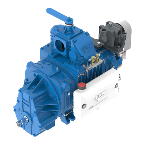
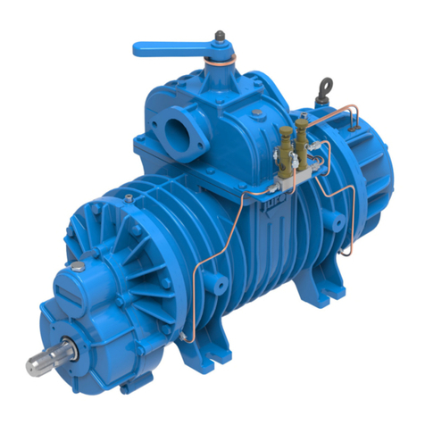
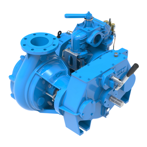
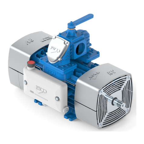
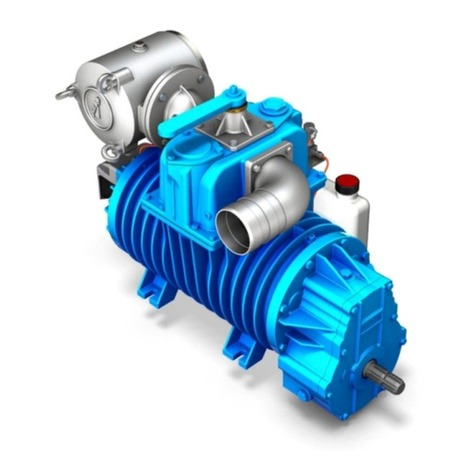
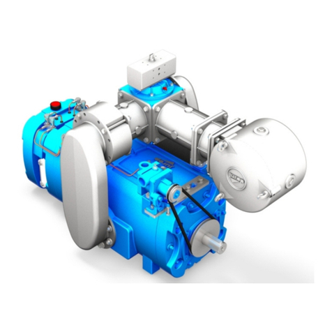
jurop PNR 104 Service manual

I
I
N
NS
ST
TA
AL
LL
LA
AT
TI
IO
ON
N
,
,
U
US
SE
E
A
AN
ND
D
M
MA
AI
IN
NT
TE
EN
NA
AN
NC
CE
E
M
MA
AN
NU
UA
AL
L
EN
PNR/PNE
104
-
124
-
PNR
142SL
Rev. 0
1
19-07-2016
O
O
R
RI
IG
GI
IN
NA
AL
L
I
I
N
NS
ST
TR
RU
UC
CT
TI
IO
ON
NS
S

R
EV
.
0
1
19-07-2016
I
NSTALLATION
,
USE AND MAINTENANCE MANUAL
–
PNR/PNR
104-124
–
PNR
142
2 / 32
Ju op
SpA
Vi Croser n° 50
33082 Azz no Decimo, PN (It li )
T
EL
.
+39
0
434
636811
F
AX
.
+39
0
434
636812
2016
–
Ju op
–
Azz no Decimo (PN)
Reproduction, electronic stor ge nd dissemin tion, even p rti l, re prohibited.
Jurop reserves the right to modify the products described in this m nu l without prior notice.
Any product n mes mentioned herein re the tr dem rks of their respective owners.

R
EV
.
0
1
19-07-2016
I
NSTALLATION
,
USE AND MAINTENANCE MANUAL
–
PNR/PNE
104-124
–
PNR
142
3 / 32
Ju op
SpA
Vi Croser n° 50
33082 Azz no Decimo, PN (It li )
T
EL
.
+39
0
434
636811
F
AX
.
+39
0
434
636812
http://www.jurop.it
e-m il: [email protected]
Contents
1. Gene al wa nings
p g. 4
1.1 Introduction 4
1.2 Sp re p rt request 4
1.3 W rr nty terms nd conditions 4
2. Technical data
p g. 5
2.1 Dimensions nd rr ngements 6
2.2 Perform nces 8
2.3 Us ge limit tions 8
2.4 Sound pressure level 9
2.5 Lubric tion 9
3. Safety and accident p evention
p g. 10
3.1 Gener l recommend tions 10
3.2 Intended use 10
4. Installation
p g. 10
4.1 Checking upon receipt 11
4.2 Storing in the w rehouse 11
4.3 Mounting 11
4.4 V cuum – Pressure Line 11
4.5 Hydr ulic ctu tor djustment 12
4.6 Pneum tic ctu tor djustment 12
4.7 Pump mounting – Drive connection 12
5. Sta t up
p g. 14
5.1 Pump st rting-up 14
5.2 Prec utions when st rting the system 14
6. Maintenance
p g. 15
6.1 Ordin ry m inten nce 15
6.2 Extr ordin ry m inten nce 16
7. Malfunctions:
t oubleshooting
p g. 19
8. Sca apping
p g. 19
S
PARE PART DATA SHEET
–
PNR/PNE
102-124
D 20
S
PARE PART DATA SHEET
–
PNR/PNE
102-124
MULTIPLIER
22
S
PARE PART DATA SHEET
–
PNR
142
D 24
S
PARE PART DATA SHEET
–
PNR
142
MULTIPLIER
26
S
PARE PART DATA SHEET
–
PNR/PNE
102-124
HDR E ACCESS
.
28
S
PARE PART DATA SHEET
–
PNR
142
HDR E ACCESSORIES
29

R
EV
.
0
1
19-07-2016
I
NSTALLATION
,
USE AND MAINTENANCE MANUAL
–
PNR/PNR
104-124
–
PNR
142
4 / 32
Ju op
SpA
Vi Croser n° 50
33082 Azz no Decimo, PN (It li )
T
EL
.
+39
0
434
636811
F
AX
.
+39
0
434
636812
http://www.jurop.it
e-m il: [email protected]
1.1. Int oduction
• This booklet cont ins the necess ry instructions for correct
inst ll tion, running, use nd m inten nce of the pump, s well s
some pr ctic l suggestions for s fe oper ting.
• The knowledge of the following p ges will gr nt long nd
trouble-free oper tion of the pump.
• Following the instructions below contributes to limiting pump rep ir
expenses by extending its dur tion, s well s preventing h z rdous
situ tions, thereby incre sing its reli bility.
• If the pump is driven by n hydr ulic motor ple se refer to
m nuf cturer's specific m nu l.
• It is recommended to:
- Re d, underst nd nd pply c refully the instructions before
running the pump.
- Keep the booklet t h nd nd h ve it known to ll oper tors.
• Below is brief description of the symbols used in this m nu l.
If these s fety rules re not respected, oper tors c n
be injured nd the pump or oilers d m ged
rem rk bly.
If these s fety rules re not respected, the pump or
system c n be d m ged.
Suggestions for n environment friendly use of the
pump.
Useful inform tion for n e sy us ge nd
m inten nce of the pump.
• The gr phic represent tions nd photogr phs cont ined in this
m nu l re there to illustr te the product in the p rts th t m ke it up
nd in specific oper ting ph ses. Though the model shown in the
m nu l m y differ from the one purch sed, the oper ting principle t
the b se of the illustr ted oper ting ph se is the s me.
• Every PNR/PNE pump h s to be fitted with its own t g reporting
the following d t : Model, Seri l number, Ye r, M x speed, M x
pressure.
Pic. 1.1
1.2. Spa e pa t equest
• Use only genuine spa e pa ts for m inten nce nd rep irs. To
order sp re p rts, provide the following det ils:
EXAMPLE:
) The model of the pump (see pump t g) PNR
104
b) The seri l number of the pump (see pump t g) K60001
c) A description of the p rts (see p rts list)
VANE
d) The qu ntity (see p rts list) n°5 pcs
e) The code number of the p rt (see p rts list) 16016 059 00
1.3. Wa anty te ms and conditions
• Compli nce with the inst ll tion, use nd m inten nce instructions
provided by this m nu l is c ucial fo the ecognition of wa anty
g inst defective p rts.
1.
Gene al wa nings

R
EV
.
0
1
19-07-2016
I
NSTALLATION
,
USE AND MAINTENANCE MANUAL
–
PNR/PNE
104-124
–
PNR
142
5 / 32
Ju op
SpA
Vi Croser n° 50
33082 Azz no Decimo, PN (It li )
T
EL
.
+39
0
434
636811
F
AX
.
+39
0
434
636812
http://www.jurop.it
e-m il: [email protected]
• Sliding v nes v cuum pump injection cooled (PNR) or n tur l ir-cooling (PNE). The PNR version is me nt for he vy duty; the PNE version for
norm l use.
• Forced oil lubric tion of both be rings nd se lings. Copper oil piping. Re r oil t nk (PNE/PNR 104-124). Side oil t nk (PNR142).
• M nifold with non-return v lve on the pump inlet.
• Built-in v cuum-pressure ch ngeover v lve. Pneum tic or hydr ulic ctu tor re v il ble.
• Tr nsmission:
- Direct with smooth or splined sh ft.
- Ge rbox tr nsmission (ASAE 1” 3/8) 540 or 1000 rpm, counter clockwise rot tion.
- Hydr ulic motor.
STANDARD EQUIPMENT
• Sliding-v nes, ir cooled vacuum pump.
• Asbestos-free tangential vanes.
• Autom tic lubric tion by me ns of volumet ic pump nd n oil
tank.
• Asymmetric l m nifold with check valve inst lled on the pump
inlet.
• Pivoting suction nd exh ust conveyo s in luminum lloy.
• Di ect t ansmission with smooth or splined sh ft (ASAE 1 3/8”).
• Gea box t ansmission with smooth or splined sh ft.
• Counte clockwise otation.
• Injection cooled (PNR) o natu al ai -cooling (PNE).
AVAILABLE ON REQUEST
• Clockwise otation.
• Tr nsmission with hydr ulic motor.
• Drive by me ns of mech nic l drive from Powe Take Off.
• Pulley for the belt drive.
• Pneumatic actuato for the v cuum/pressure ch ngeover v lve.
• Hyd aulic actuato for the v cuum/pressure ch ngeover v lve.
P
PN
NR
R
/
/
P
PN
NE
E
2.
Technical data
AIR INJECTION VALVES
(
PNR
)
MANIFOLD WITH NON
-
RETURN VALVE ON THE PUMP INLET
EUROPEAN PATENT APPL
ICATION
PUMP HOUSING
GEARBOX
OIL TANK
OIL FILLING PORT AND
D
IP STICK
VACUUM
/
PRESSURE
CHANGEOVER VALVE
CONVEYOR
SUCTION
/
EXHAUST
AUTOMATIC
LUBRICATING PUMP
SIDE OIL TANK
VANES INSPECTION
PORT
DRIP OILERS
VACUUM
/
PRESSURE
CHANGEOVER VALVE

R
EV
.
0
1
19-07-2016
I
NSTALLATION
,
USE AND MAINTENANCE MANUAL
–
PNR/PNR
104-124
–
PNR
142
6 / 32
Ju op
SpA
Vi Croser n° 50
33082 Azz no Decimo, PN (It li )
T
EL
.
+39
0
434
636811
F
AX
.
+39
0
434
636812
http://www.jurop.it
e-m il: [email protected]
2.1 Dimensions and a angements
WEIGHT PNR/PNE 104 PNR/PNE 124 PNR 142 SL
Direct tr nsmission (smooth or splined sh ft) 150 Kg 177 Kg 210 Kg
Ge rbox tr nsmission (540 rpm) 173 Kg 190 Kg 225 Kg
Ge rbox tr nsmission (1000 rpm) 173 Kg 190 Kg 230 Kg
Hydr ulic motor 180 Kg 210 Kg 224 Kg
PNR/PNE 104-124 Di ect t ansmission
Mod. A B B1 C D D1 E E1 F F1 G H I L M N O P Q R S
PNR104 321 329 313 153 253 238 320 320 83 67 67 16,5 368 285 249 534 367 167,5 40 43 12
PNR124 353,5 362 346 153 285 269 352 352 83 67 67 16,5 368 285 249 534 367 167,5 40 43 12
PNR/PNE 104-124 Gea box t ansmission
Mod. A A1 B C D E F G H I L M N O P Q
PNR104 727 791 406 153 329 85,5 67 16,5 368 285 249 600 534 367 50 62
PNR124 792 856 437 153 368 85,5 67 16,5 368 285 249 600 534 367 50 62

R
EV
.
0
1
19-07-2016
I
NSTALLATION
,
USE AND MAINTENANCE MANUAL
–
PNR/PNE
104-124
–
PNR
142
7 / 32
Ju op
SpA
Vi Croser n° 50
33082 Azz no Decimo, PN (It li )
T
EL
.
+39
0
434
636811
F
AX
.
+39
0
434
636812
http://www.jurop.it
e-m il: [email protected]
PNR/PNE 104-124 Hyd aulic moto
Mod. A B C D E F G H I L M N O P1 P2
PNR104 907 586 153 510 67 16,5 136 258 368 285 249 534 367 1” ½ 1” ¼
PNR124 955 502 153 525 67 16,5 144 258 368 285 249 534 367 - -
PNR 142 Side oil tank
PNR142
M
(540-1000
RPM
) PNR142
D PNR142
HDR

R
EV
.
0
1
19-07-2016
I
NSTALLATION
,
USE AND MAINTENANCE MANUAL
–
PNR/PNR
104-124
–
PNR
142
8 / 32
Ju op
SpA
Vi Croser n° 50
33082 Azz no Decimo, PN (It li )
T
EL
.
+39
0
434
636811
F
AX
.
+39
0
434
636812
http://www.jurop.it
e-m il: [email protected]
2.2 Pe fo mances
Pe fo mances PNR/PNE 104 D PNR/PNE 104 M PNR/PNE 104 HDR
M ximum speed 1300 rpm 540 - 1000 rpm 1300 rpm
Air flow t free ir condition 10400 l/min - 624 m³/h 10400 l/min - 624 m³/h 10400 l/min - 624 m³/h
Air flow t 60% v cuum r te 9400 l/min - 564 m³/h 9400 l/min - 564 m³/h 9400 l/min - 564 m³/h
M ximum v cuum 95 % 95 % 95 %
M ximum v cuum t continuos duty PNR 70 % 70 % 70 %
M ximum v cuum t continuos duty PNE 60 % 60 % 60 %
Power required t 0,5 b r rel (1,5 b r bs) 14 kW 14 kW 14 kW
M x oper ting rel. pressure ( bs.) t continuos duty 1 b r (2 b r bs) 1 b r (2 b r bs) 1 b r (2 b r bs)
M x oper ting rel. pressure 2,5 b r bs 2,5 b r bs 2,5 b r bs
Oil consumption 130-150 g/h 130-150 g/h 130-150 g/h
Oil t nk c p city 3,2 l 3,2 l 3,2 l
Pe fo mances PNR/PNE 124 D PNR/PNE 124 M PNR/PNE 124 HDR
M ximum speed 1300 rpm 540 - 1000 rpm 1300 rpm
Air flow t free ir condition 12400 l/min - 744 m³/h 12400 l/min - 744 m³/h 12400 l/min - 744 m³/h
Air flow t 60% v cuum r te 11200 l/min - 672 m³/h 11200 l/min - 672 m³/h 11200 l/min - 672 m³/h
M ximum v cuum 95 % 95 % 95 %
M ximum v cuum t continuos duty PNR 70 % 70 % 70 %
M ximum v cuum t continuos duty PNE 60 % 60 % 60 %
Power required t 0,5 b r rel (1,5 b r bs) 16 kW 16 kW 16 kW
M x oper ting rel. pressure ( bs.) t continuos duty 1 b r (2 b r bs) 1 b r (2 b r bs) 1 b r (2 b r bs)
M x oper ting rel. pressure 2,5 b r bs 2,5 b r bs 2,5 b r bs
Oil consumption 130-150 g/h 130-150 g/h 130-150 g/h
Oil t nk c p city 3,2 l 3,2 l 3,2 l
Pe fo mances PNR142 D PNR142 M (540 pm) PNR142 M (1000 pm) PNR142 HDR
M ximum speed 1200 rpm 540 rpm 1000 rpm 1200 rpm
Air flow t free ir condition 14200 l/min - 852 m³/h 14200 l/min - 852 m³/h 14200 l/min - 852 m³/h 14200 l/min - 852 m³/h
Air flow t 60% v cuum r te 12800 l/min - 768 m³/h 12800 l/min - 768 m³/h 12800 l/min - 768 m³/h 12800 l/min - 768 m³/h
M ximum v cuum 95 % 95 % 95 % 95 %
M ximum v cuum t continuos duty 70 % 70 % 70 % 70 %
Power required t 0,5 b r rel (1,5 b r bs) 20,5 kW 20,5 kW 20,5 kW 20,5 kW
M x oper ting rel. pressure ( bs.) t continuos duty 1 b r (2 b r bs) 1 b r (2 b r bs) 1 b r (2 b r bs) 1 b r (2 b r bs)
M x oper ting rel. pressure 1,5 b r (2,5 b r bs) 1,5 b r (2,5 b r bs) 1,5 b r (2,5 b r bs) 1,5 b r (2,5 b r bs)
Oil consumption 160-170 g/h 160-170 g/h 160-170 g/h 160-170 g/h
Oil t nk c p city 4 l 4 l 4 l 4 l
REFERENCE CONDITIONS
Conveyed g s: ir V cuum condition: tmospheric disch rge
Ambient reference temper ture: 20°C (68°F) Pressure condition: tmospheric suction
Absolute reference pressure: 1013mb r (14.7psi) Actu l perform nce m y v ry of ± 5%
2.3 Usage limitations
Model Max. Speed ( pm) P
(ba ABS) T
(°C) Room Tempe atu e
Di ect - HDR Mult - 540 Mult - 1000 PNR PNE
PNR / PNE 104 850 - 1300 360 - 540 650 - 1000 2,5 b r bs 180 °C 160 °C -20 / +40°C
PNR / PNE 124 850 - 1300 360 - 540 650 - 1000 2,5 b r bs 180 °C 160 °C -20 / +40°C
PNR 142 850 - 1300 360 - 540 650 - 1000 2,5 b r bs 180 °C 160 °C -20 / +40°C
P: bsolute pressure during delivery T: temper ture during delivery

R
EV
.
0
1
19-07-2016
I
NSTALLATION
,
USE AND MAINTENANCE MANUAL
–
PNR/PNE
104-124
–
PNR
142
9 / 32
Ju op
SpA
Vi Croser n° 50
33082 Azz no Decimo, PN (It li )
T
EL
.
+39
0
434
636811
F
AX
.
+39
0
434
636812
http://www.jurop.it
e-m il: [email protected]
2.4 Sound p essu e level
Sound p essu e level PNR104 PNE104 PNR124 PNE124 PNR142sl
60% v cuum r te, dist nce of 7 meter dB (A) 78 75 78 75 78
2.5 Lub ication
Recommended oils nd gre ses: OIL TANK
Room T Viscosity Type ENI ESSO SHELL TOTAL MOBIL BP
TEXACO
HAVOLINE
< 10°C ISO VG 46 Miner l Oil Acer 46 Nuto 46 Morlin oil 46 Droser MS 46 Nuto H 46 B rtr n HV 46 R ndo HD 46
> 10°C ISO VG 150 Miner l Oil Acer 150 Nuto 150 Morlin oil 150 Droser MS 150 Nuto H 150 B rtr n HV 150 R ndo HD 150
Recommended oils nd gre ses: GEARBOX
Viscosity Type ENI ESSO SHELL TOTAL MOBIL BP
TEXACO
HAVOLINE
ISO VG 220 Miner l Oil Bl si 220 Sp rt n EP 220 Om l oil 220 C rter EP 220 Mobilge r 630 Energol GR XP 220 Merop 220

R
EV
.
0
1
19-07-2016
I
NSTALLATION
,
USE AND MAINTENANCE MANUAL
–
PNR/PNR
104-124
–
PNR
142
10 / 32
Ju op
SpA
Vi Croser n° 50
33082 Azz no Decimo, PN (It li )
T
EL
.
+39
0
434
636811
F
AX
.
+39
0
434
636812
http://www.jurop.it
e-m il: [email protected]
Attention: ca efully apply these p esc iptions.
3.1 Gene al ecommendations
• Inst ll tion nd m inten nce must be c rried out with the unit
tot lly diseng ged from its drive system nd must be performed by
qu lified personnel.
• Use dequ te clothing ( void ties, loose sleeves, neckl ces nd so
on) nd suit ble protection equipment (gloves, protection gl sses,
boots...).
• To prevent errors nd h z rdous situ tions, est blish wh t e ch
oper tor is responsible for in the different m inten nce oper tions.
• Dur nte il tr sporto del decompressore utilizz re degu te
imbr c ture. Appoggi re il decompressore su punti st bili.
• When tr nsporting the compressor use proper slinging. Store the
compressor in st ble pl ces.
• Before e ch m inten nce oper tion, stop the pump nd restore
the tmospheric pressure.
• M ke sure th t ll the p rts of the unit re idle nd cool, before
performing ny m inten nce oper tion.
• When the pump is running, some p rts m y re ch very high
temper tures ( bove 100°C). Use ll necess ry prec utions to void
cont ct.
• Oper tors working ne rby must void prolonged exposure to the
noise emitted by the spir tor, if not equipped with the proper e r-
protection devices.
• Avoid ccident l suction of solids: solids m y be projected t high
speed through the exh ust m nifold nd c use injures. A filter must be
mounted on the sunction line (Mesh 55).
• Do not st rt the m chine if the protection devices provided for
tr nsmissions re removed. Repl ce d m ged p rt.
• Pressure relief v lve: point the ir flux w y from the oper tors.
• Do not use the spir tor over its designed limits: the m chine m y
be d m ge nd the oper tor m y be injured.
Do not exceed the speed and the powe supply
pa amete s indicated in the technical tables (see
pa . 2.2 - 2.3).
3.2 Intended use
• V cuum pumps of the PNR/PNE series re commonly used on
st tion ry or mobile equipment for suction nd tr nsfer by me ns of
v cuum or soc lled pneum tic-tr nsport tion of liquid nd solid w stes.
• They re ir-cooled nd consequentely foreseen for non-
continuous duty. The mod. PNE nd the mod. PNR, the l tter supplied
with ir injection system (fig. 1) nd me nt for he vy duty works, do not
ccept oper ting temper tures over 150 °C (300 °F), checked t not
more th n 150 mm from the disch rge connections.
• Evit re l’ spir zione di m teri li tossici e di g s infi mm bili o
esplosivi poiché i componenti interni possono r ggiungere temper ture
elev te.
• Avoid suction of liquids or solids, they c n seriously d m ge the
pump.
• Do not run the pump over its designed oper ting limits (see p r.
2.3): it m y bre k nd tr nsmission c n be d m ged.
M in components legend
1. V cuum/Pressure ch nge-over v lve
2. Air injection v lves (PNR)
3. Oil t nk
4. V nes inspection port
5. Ge r box oil filling plug
6. Ge r box oil level plug
7. Drip oilers
8. Oil filling port nd dip stick
9. Exh ust conveyor
10.
Suction conveyor
11.
Pressure relief v lve port.
Available only if foreseen with additional conveyor
Code 627 02500.
12.
Non-returne v lve (Int ke m nifold)
Pic. 4.1
4. Installation
3.
Safety and accident p evention
x
y
PNR/PNE 104-124
PNR 142 SL

R
EV
.
0
1
19-07-2016
I
NSTALLATION
,
USE AND MAINTENANCE MANUAL
–
PNR/PNE
104-124
–
PNR
142
11 / 32
Ju op
SpA
Vi Croser n° 50
33082 Azz no Decimo, PN (It li )
T
EL
.
+39
0
434
636811
F
AX
.
+39
0
434
636812
http://www.jurop.it
e-m il: [email protected]
4.1. Checking upon eceipt
• When the goods re delivered, m ke sure th t ll p rts listed on
the delivery note re in perfect condition nd h ve suffered no d m ge
during shipping.
• M ke sure the v cuum pump h s its identific tion pl te. Pumps
without such identific tion re to be considered nonymous nd
potenti lly d ngerous: in such n event, they must not be used,
otherwise the m nuf cturer will be deemed free from ny li bility
wh tsoever.
• Pump must be kept in dry stor ge re . During stor ge, inlet nd
outlet ports must be kept closed.
4.2. Sto ing in the wa ehouse
• If the compressor will not be inst lled inside short time fter
delivery:
- Remove the gu rds from the ports nd spr y film of
protective oil over the inner surf ces of the body, rotors nd
sides. Then tt ch g in the gu rds;
- Store in closed nd dry pl ce. Renew the preserving oil
periodic lly.
• To tempor rily store used pump, follow the instructions below:
- Thoroughly cle n the pump.
- Equip the pump with suit ble nti-corrosion protection.
4.3. Mounting
• The pump must be ssembled for n e sy ccess for m inten nce
oper tions nd secured rigidly to fr me or levelled b se (m x. 3°
sl nt to the horizont l pl ne. See Fig. 4.1). The b se must be such s
to void vibr tions, bending or deform tion.
• Le ve enough sp ce round the pump to llow the free circul tion
of ir for cooling; void exposure to dirt nd debris.
• Provide the necess ry sp ce to re ch ll points of lubric tion
control (oil level), nd the oil t nk filler c p, the lever of the 4-w y
switch, v nes inspection ports. See Pic. 4.1.
• For PNR/PNE 104-124 the oil t nk is mounted on the re r side of
the pump. Inste d for PNR142 the oil t nk is mounted on the suction
side of the housing.
• In c se of PNR/PNE with hydr ulic motor, provide the necess ry
sp ce to dis ssemble the motor itself nd proceed with joint lubric tion.
4.4. Vacuum / P essu e line
• See picture 4.2.
Pic. 4.2
• The hoses connecting the suction nd exh ust ports of the v cuum
pump must be of degu te di meter (suggested not less th n 3”) nd of
oil nd corrosion resist nt m teri ls nd before connecting them, m ke
sure th t they re perfectly cle n in the inside.
• The weight or dimensions of the pipes must in no w y stress the
PNR/PNE body. Use high temper ture resist nt rubber sleeves.
• Remove the port gu rds when mounting. The pipes nd
components of the whole line must be cle n.
• Avoid constrictions nd tight curves where they re not essenti l.
• Connect the pump to the t nk through the suction m nifold (Fig.
4.1 - pos. 10) which h s thre ded port for fitting the over-pressure
v lve.
• The exh ust pipes c n re ch high temper tures. Protect those
dequ tely from the oper tor re ch.
• A cl pet v lve on suction pipe voids rot tion in the opposite
direction when the pump stops.
• To void th t foreign liquids will enter the v cuum pump it is
necess ry to mount on the suction line n over-flow v lve of “flo ting-
b ll” type (Fig. 4.2. - pos. 1). The flow section of this v lve must be
equiv lent to the suction hose’s one.
• It is lso necess ry to h ve on the line suit ble ir filter for
preventing solids to be sucked inside the v cuum pump. It is lso
recommended to mount “second ry shutoff” of flo ting-b ll type (Fig.
4.2 - pos. 2) between v cuum pump nd over-flow (prim ry shutoff),
long with the previously mentioned ir filter (Fig. 4.2 - pos. 3).
• C lled lso 4-w y v lve, norm lly is m nu lly oper ted but it c n
be t ny time tr nsformed in pneum tic lly or hydr ulic oper ted upon
request of the ppropri te kit.
• During norm l running of the pump the resulting noise should be
reduced by me ns of suit ble silencer (Fig. 4.2 - pos. 4) mounted s
close s possible to the pump itself. It h s to be dimensioned for the ir
flow produced by the pump model. The oil used for the pump’s inside
lubric tion h s to be sep r ted from the exh usted ir by me ns of n
dequ te oil-sep r tor, pl ced directly inside the silencer.
Vacuum / P essu e line components
1 Prim ry shutoff
2 Second ry shutoff
3 Suction filter
4 Silencer
5 Over-pressure s fety relief v lve
6 V cuum control v lve
4
5
6
1
2
3

R
EV
.
0
1
19-07-2016
I
NSTALLATION
,
USE AND MAINTENANCE MANUAL
–
PNR/PNR
104-124
–
PNR
142
12 / 32
Ju op
SpA
Vi Croser n° 50
33082 Azz no Decimo, PN (It li )
T
EL
.
+39
0
434
636811
F
AX
.
+39
0
434
636812
http://www.jurop.it
e-m il: [email protected]
The silencer is fitted lso with dr ining t p for the collected oil nd
condensed liquids.
• Over-pressure s fety relief v lve (Pic. 4.2 - pos. 5). It must be
dimensioned to disch rge the entire ir-flow of the pump. The
djustement of this v lve h s to be kept inside 10% of toller nce of the
pump's working pressure nd in ny c se it h s to st y inside the given
v lue of the t nk's work pressure.
• V cuum control v lve h s to be fitted on the suction piping, if the
t nk's ch r cteristics or the v cuum line will need this kind of v cuum-
limiting device.
Pic. 4.3
• For pumps th t re ch, during norm l oper ting, disch rge ir
temper ture close to 150 °C (300°F) - (checked t not more th n 150
mm from the disch rge connection) it is necess ry to use device
(overhe ting limiter) th t will not llow to exceed such temper ture.
Cont ct our Technic l Dep rtment.
• An djust ble curved pipe is inst lled on the outlet of the silencer,
in order to prevent r in from entering nd to en ble positioning (during
inst ll tion) of the output irflow.
• Direct the silencer disch rge output w y from the silencer suction
inlet in order to prevent the input of hot fluids into the injection inlet.
Attention: di ect the silence discha ge output
away f om the silence suction inlet.
4.5 Hyd aulic actuato adjustment
• Extr ordin ry m inten nce oper tions c n require the upper cover
( nd th t of the ctu tor, either m nu l or pneum tic) to be removed.
We recommend ensuring enough sp ce to c rry out such oper tions.
• If the cock blocks or it moves with friction, screw up the cle r nce
regul tion nut (A). Screw up ¼ of turn e ch time. Block the nut rot tion
with the s fety nut.
• The lubric tion points (B) nd the cle r nce regul tion bolt (A)
must be ccessible. See Fig. 4.5.
• Lubric te with gre se every 1000 cycles. Gre se type NLGI 2.
• It is suggested to inst ll 2 one‐w y flow controller between the
hydr ulic switch nd the hydr ulic ctu tor. Set the flow controllers in
order to prevent h rd hitting through the end of stroke. Minimum
commut tion time: 1 second.
• M ximum feed pressure: 30 b r.
• To order sp re p rts see sp re p rts list t the end of this m nu l.
Pic. 4.4
4.6 Pneumatic actuato adjustment
• In the event of 4-w y v lves equipped with pneum tic ctu tor, we
recommend inst lling two one-w y flow regul tors between the
pneum tic “control” nd the pneum tic ctu tor. The following figure
shows schem tic view of possible pneum tic inst ll tion.
Pic. 4.5
• We recommend djusting the two flow regul tors in order for
rot tion to occur without knocks nd with switching time of t le st
one second.
4.7. Pump mounting - d ive connection
A) Ca dan shaft d ive
• Use telescopic c rd n sh fts.
• In order to chieve uniform motion of the driven sh ft, the
following requirements must be met (see Pic. 4.6):
- Equ l working ngle α nd α1 of both couplings;
- The intern l fork joints must be copl n r;
- Both driven nd driving sh fts must be copl n r.
• It is lso recommended working with limited rticul ted joint ngles
(m x 15° t 1000 rpm nd m x 11° t 1100 rpm) nd diseng ging the
tr nsmission for those oper tions requiring gre t ngles (steering or
lifting).
VACUUM CONTROL VALVE
SET UP

R
EV
.
0
1
19-07-2016
I
NSTALLATION
,
USE AND MAINTENANCE MANUAL
–
PNR/PNE
104-124
–
PNR
142
13 / 32
Ju op
SpA
Vi Croser n° 50
33082 Azz no Decimo, PN (It li )
T
EL
.
+39
0
434
636811
F
AX
.
+39
0
434
636812
PORT
Pic. 4.6
Follow the otation di ection as indicated on the
pump f ont conveyo p otection. Follow the
inst uctions of the ca dan shaft’s manufactu e.
• Use the protection th t comes with the Juli group sh ft.
Use the ca dan p otection supplied with the
pump. The pump installation must fulfill the
cu ent EC inju y p evention specifications.
B) Belt d ive
Pic. 4.7
• Inst ll suit ble pulley on the smooth sh ft s close s possible
to the pump in order to void excessive bending stress on the drive
sh ft.
• Apply n dequ te belt tension (see list below).
• Do not use driven or driving pulleys with pitch di meter inferior
to v lues reported in the box below. Sm ll pulleys require high belt
tension which m y c use prem ture we r to the be ring or
tr nsmission d m ges.
Model Max. Speed ( pm) T. max (N) L. max (mm) Pitch diamete (mm) N . G ooves Belts type
PNR/PNE104 1300 3300 35 200 2 XPB
PNR/PNE124 1300 3300 35 200 2 XPB
PNR 142 (1 b r bs) 1300 3300 35 200 3 XPB
Pitch Di meter. min.: Minimum drive of pulley pitch di meter.
C) Hyd aulic d ive t ansmission (PNR/PNE HDR)
Model Displacement Ope ating p essu e
(max. vac.)
Ope ating p essu e
(1 el. ba ) Flow Max p essu e
d aining line
Max. p essu e
moto exhaust Max p essu e
PNR/PNE104
61 cc/rev 130 b r 170 b r 83 l/min (1300rpm) 5 b r 5 b r 180 b r
PNR/PNE124
72 cc/rev 130 b r 170 b r 98 l/min (1300rpm) 5 b r 5 b r 220 b r
PNR 142 86 cc/rev 150 b r 200 b r 110 l/min (1200rpm) 5 b r 5 b r 220 b r
(*) : Oil temper ture, used in the m in circuit.
• Fluid: miner l oil for hydr ulic systems in compli nce with ISO/DIN.
Tempe atu e Optimum viscosity ale Max. viscosity allowed
-20 / +80 °C 12 – 100 cSt 750 cSt
• Filt ation: cl ss 21/19/16 cont min tion ccording to ISO 4406 to
be obt ined with ßx = 75 filter.
• Check ci cuit connections: they must be pplied in the s me
rot tion direction s th t indic ted by the rrow on the pump front
fl nge.
• D aining: connect directly to the t nk bove the m ximum oil
level. Oper ting without dr ining line m y d m ge the motor.
Pic. 4.8
DP MIN
KEEP AXELS PARALLEL
ALINGN PULLEY GROVES AND BELTS
CHECK BELT TENSION
T
MAX

R
EV
.
0
1
19-07-2016
I
NSTALLATION
,
USE AND MAINTENANCE MANUAL
–
PNR/PNR
104-124
–
PNR
142
14 / 32
Ju op
SpA
Vi Croser n° 50
33082 Azz no Decimo, PN (It li )
T
EL
.
+39
0
434
636811
F
AX
.
+39
0
434
636812
http://www.jurop.it
e-m il: [email protected]
• Dist ibuto : open-centre distributor in centr l idle position
(v cuum pump off). It must be equipped with n djust ble
overpressure s fety v lve.
• Moto pipeline: outlet pipe must not be of sm ller di meter th n
th t of the inlet port. Inlet pipes lw ys h ve di meter sm ller th n
outlet pipes. Choose prefer bly flexible pipes to void vibr tion
tr nsmission.
• Tank: with suction pipe nd return sep r ted by b ffles. If
necess ry, use he t exch nger to void oil he ting bove 70-80°C
nd protect it from extreme pressure with pressure relief v lve.
Minimum pproxim te c p city: s twice s the circul tion flow.
Pic. 4.9
1 Hdr pump 4 Oil filter
2 Distributor 5 * He t exch nger
3 Hdr motor 6 * S fety v lve
* option l components
• Sta ting-up: be sure th t the system is well cle ned nd pour oil
into the t nk nd into the motor housing (necess ry to lubric te the
intern l be rings).
• Vent the circuit nd djust the overpressure s fety v lve to the
lowest possible v lue.
• Check the oil t nk level.
• Incre se pressure nd rot tion speed until oper ting v lues re
re ched.
• The m chine/system m nuf cturer is responsible for dimensioning
the lines.
The machine/system manufactu e is esponsible
fo dimensioning the lines.
5.1. Pump sta ting-up
• Before st rting the equipment check the lubric ting oil level of the
pump.
• Refill the t nk with lubric tion oil.
• Check the oil level in the ge r box (if the pomp is provided with it).
• In order to choose the most suit ble oil, see p r gr ph. 2.5.
• Check th t ll protection nd s fety devices re correctly inst lled.
• Check th t no obst cles obstruct the v cuum nd pressure line or
the ir injection cooling system.
• Check rot tion direction: open ll system v lves nd st rt running
t slow speed.
Do not otate in the w ong di ection:pump may be
damaged.
• Check which position of the 4-w y integr ted v lve lever llows
v cuum or pressure functioning.
• If the pump h s been in stor ge for long time: inlet. liter of oil in
the pump for n e sy cle ning of intern l p rts.
• Close the v lve nd incre se v cuum r te (or oper ting pressure).
• Check lo ding nd oper ting speed for vibr tions or unusu l
noises.
This vacuum pump is designed to wo k at
maximum speed. Fo longe ope ating we
ecommend the pump be un at wo king speed.
• Prep re dequ tely tr nsmission.
5.2. Ope ating p ecautions
• Run the v cuum pump t room temper ture of -20°C e +40°C.
• Do not m ke the v cuum pump overhe t. M ximum ir
temper ture on exh ust (or delivery) side: 150°C.
• Do not oper te the pump without lubric tion: it m y c use quick
we r nd possible bre kdown of v nes.
• Do not st rt running the pump under lo d: th t c uses stress to the
drive system nd the hydr ulic motor.
• Check rot tion speed. The v cuum pump must never exceed the
m ximum speed or run below the minimum speed.
• Do not ccident lly oper te the pump in the wrong direction: it m y
bre k the v nes.
• Do not convey the exceeding delivery outlet tow rds the suction
port, otherwise it will s ck w rm g s.
• Control the ir flow by djusting the rot tion speed: do not use the
pressure relief v lve to disch rge the exceeding flow.
• Once th t the w nted v cuum r ted h s been tt ined it is
recommend ble to decre se the speed. (see p r. 2.3): This useful
procedure, th t will not incre se the time requested to fill up the t nk,
5
.
Sta t up
5
4
6
1
3
P
A B
OUT IN
DRAINING LINE
4
6
3
5
2
1

R
EV
.
0
1
19-07-2016
I
NSTALLATION
,
USE AND MAINTENANCE MANUAL
–
PNR/PNE
104-124
–
PNR
142
15 / 32
Ju op
SpA
Vi Croser n° 50
33082 Azz no Decimo, PN (It li )
T
EL
.
+39
0
434
636811
F
AX
.
+39
0
434
636812
http://www.jurop.it
e-m il: [email protected]
will however result in lesser we r of the v nes. It is suggested to
reduce the speed lso when oper ting with pressure.
• When, exh ust temper ture is reduced, v ne dur bility is
incre sed nd both oil consumption nd power bsorption re reduced.
Once the needed vacuum ate has been eached,
we ecommend educing the vacuum pump
speed to its wo king speed.
• Intern l w sh-up is necess ry fter prolonged in ctivity, fter
working in dusty environments or in c se of ccident l suction of
liquids. Such oper tion must be c rried out only on cooled pumps.
1. Disconnect the exh ust silencer, if possible;
2. St rt running the pump t low speed;
3. Suck some w ter ( bout 1-2 litres) through the inlet port;
4. Then suck oil ( bout 1 litre) to complete the w sh-up nd lubric te
intern l components.
In case the exhaust line cannot be disconnected,
d ain the liquids accumulated in the sepa ato of
the exhaust silence .
• With temper ture below 5 °C (40 °F) nd long periods of in ctivity,
introduce some qu ntity of oil through the suction connection before
st rting off the pump.
• The ir injection cooling system gr nts the use of the v cuum
pump t high v cuum r tes. Anyw y it h s to be remembered th t the
pump h s been designed for non-continuous work. This cooling system
llows to dissip te p rt of the ccumul ted he t still t s tisf ctory
lubric tion conditions. Continuous, he vy-duty work, or prolonged work
periods will c use n over-he ting of the pump, consequently reducing
perform nces nd dur bility.
• With the PNR models it is quite norm l th t the v cuum r te in the
t nk will f ll down t bout 50%, if nd when the pump is stopped for
sufficient time. This bec use tmosferic ir will flow b ck in the t nk
through the injection v lves, which re djusted t pproxim tely 0,5
b r. Vent the t nk nd t ke it to tmospheric pressure when stopping
the pump in order to void b ck rot tion of the pump.
6.1. O dina y maintenance
• Inst ll tion nd m inten nce must be oper ted only by qu lified personnel we ring the proper clothes nd the necess ry tools s well s
protection devices.
• Use suit ble protection equipment (gloves, protection gl sses, boots...)
• In the following t ble summ rizes the m in controls to be performed nd the frequency of intervention.
Ope ating
Condition Maintenance A ea Check 8
H
50
H
500
H
1000H
OPERATING
V cuum line Check s fety v lve (non-return v lve)
Oper ting pressure
Tr nsmission / Pump
Lubric tion: dripping into oilers (PNR 142)
Rot tion speed
Sound pressure level ( lso HDR motor)
STANDSTILL
V cuum line Suctions filters
4-w y ch ngeover v lve: check nd lubric te
Pump
Cle n oilers gl sses (PNR 142)
Check oil level
Check v nes we r
Ch nge oil (*)
Pump’s inner w shing (**)
Over ll
Gre sing
Check c rd n sh ft drive
Ch ck tr nsmission pulley
(*)The first oil ch nge must be done inside 500 hours oper tion. Following
ch nges every 5000 hours or 12 months. In order to choose the most suit ble oil, see
p r gr ph 2.5.
(**) After oper tion in dusty environments, fter ccident l sucking of liquids
inside the pump or before long inoper tivity period it is recommended to w sh the
pump inside ccording to the procedure described t p r gr ph 5.2.
Checking lub ification (PNR 142 only)
• Check dripping into the oilers.
• Be sure it is regul r ( bout 60 drops/min t m x. speed, with free
ports) to gr nt correct lubric tion of the pump. At lower speeds, the
number of drops must be directly proportion l.
6
.
Maintenance

R
EV
.
0
1
19-07-2016
I
NSTALLATION
,
USE AND MAINTENANCE MANUAL
–
PNR/PNR
104-124
–
PNR
142
16 / 32
Ju op
SpA
Vi Croser n° 50
33082 Azz no Decimo, PN (It li )
T
EL
.
+39
0
434
636811
F
AX
.
+39
0
434
636812
http://www.jurop.it
e-m il: [email protected]
If the pump is unning without lub ication, the
inte nal components may quickly damaged due to
ove heating. Stop the vacuum pump and check the
oil level and the lub icating pump.
Checking the oil tank level
• Check the oil t nk level.
• Do not run the pump with oil level under the minimum level: th t
m y le d to dry functioning nd c use serious d m ges. (Fig. 6.1).
• Check the oil level in the ge r box (if the pomp is provided with it).
Pic. 6.1
• Re r mounted t nk c p city: 3,2 l.
• Side mounted t nk c p city: 4 l.
• Use pure nd fresh oil. In order to choose the most suit ble oil,
see p r gr ph 2.5.
Checking the vanes wea
• Unscrew the v nes we r check-plug on the front fl nge. See Pic.
6.2.
Pic. 6.2
• Turn the sh ft by h nd until v nes ppe r nce.
• V nes usu lly slip on se t bottom due to gr vity. Check their right
entry in the se t.
• Insert Ø 6 mm stick until it touches the rotor nd then m rk like
in Pic. 6.3.
• Turn the rotor slowly until the stick touches the v ne in idle
position in its se t. The v nes slide to the bottom of the se t due to
gr vity: check they re lly do nd m rk g in on the stick.
• Repe t the s me procedure for ll the v nes. If we r exceeds 10
mm: repl ce the v nes s soon s possible.
Pic. 6.3
• Repl ce ll the pump v nes t the s me time.
Replace the vanes when thei wea exceeds 10
mm (L – L min): they may b eak. Replace all
vanes at the same time.
• Repl ce the c p fter the me surement.
6.2. Ext ao dina y maintenance
• Before st rting ny extr ordin ry m inten nce oper tion, be sure
the pump st nds still nd follow the s fety prescriptions s described in
C p. “S fety nd ccident prevention”.
Replacing the vanes (PNR/PNE 104-124)
• Remove the v cuum pump from its be ring fr me nd w sh it
before dis ssembling.
• It is suggested to remove the oil t nk on the re r p rt bec use
gener lly the pump’s drive components re fitted on the front fl nge.
Use lw ys the specific kit of g skets for the pump model t h nd (see
lso sp re p rts list).
• M teri l th t is subject to we r: repl ce.
Pic. 6.4
VANES
CHECK
-
PLUG
REAR MOUNTED TANK
SIDE MOUNTED TANK

R
EV
.
0
1
19-07-2016
I
NSTALLATION
,
USE AND MAINTENANCE MANUAL
–
PNR/PNE
104-124
–
PNR
142
17 / 32
Ju op
SpA
Vi Croser n° 50
33082 Azz no Decimo, PN (It li )
T
EL
.
+39
0
434
636811
F
AX
.
+39
0
434
636812
http://www.jurop.it
e-m il: [email protected]
Pos. Code Desc iption
1 1684000000 PLUG 3/8
2 1640101200 TANK’S CAP
3 1680707700 CAP’S GASKET
4 4026706101 PIPE’S FITTING
5 4024251000 OIL PUMP (RIGHT)
4024251500 OIL PUMP (LEFT)
6 4022200111 SEAL 72X48X15
7 16125006E0 OIL TANK
8 4022200309 OR
9 1610508500 PUMP’S FLANGE
10 4026300020 COMPENSATION RING
11 4023100140 BEARING
Disassemble ope ation
• Dr in the oil t nk through the proper port (pos. 1).
• Remove the t nk’s c p (pos. 2) nd ch nge the g sket (pos. 3);
unscrew the lubric tion pipe’s fittings (pos .4) connecting the oil pump
to the oilers.
• Remove the oil pump (pos .5).
• Remove the screws fixing the oil t nk (pos. 7) nd c refully
remove it, eventu lly using two screws p rti lly winded inside the
thre ds. Avoid th t the rotor f lls down inside the housing, supporting it
if necess ry with dequ te tools.
• Ch nge the OR (pos. 8).
• Remove the oil pump’s fl nge (pos. 9), the compens tion ring
(pos. 10) nd the be ring (pos. 11) this will m ke the re ssembly of the
oil t nk much e sier (pos. 7).
• Lubric te the new v nes before inserting them in the rotor’s slots.
• The new v nes h ve to be inserted with the rounded corner f cing
tow rds the housing (See Pic. 6.5).
Pic. 6.5
Assemble ope ation
• Re ssemble everything g in in the right sequence, bsolutely
voiding to le ve foreign p rts inside the pump. Alw ys ch nge ll the
g skets nd the OR fter h ving them properly lubric ted nd lso the
se l (pos. 6) if necess ry. ut some gre se in the sp ce between the
be ring (pos. 11) nd the fl nge (pos. 9).
• Re ssemble the oil t nk (pos. 7) nd the OR (pos. 8) c refully
inserting the drive sh ft without d m ging the se l.
• Insert the be ring (pos. 11), the compens tion ring (pos. 10), nd
the oil pump’s fl nge (pos. 9).
• Insert correctly the lubric tion pump in the driving slot nd refit the
fl nge.
• Re ssemble the lubric tion pipes nd fittings.
• Re ssemble the t nk’s c p (pos. 2) nd the g sket (pos. 3).
• Repl ce the plug on the t nk (pos. 1) nd refill it with lubric tion
oil.
Replacing the vanes (PNR 142)
• Remove the v cuum pump from its be ring fr me nd w sh it
before dis ssembling.
• It is suggested to remove the oil t nk on the re r p rt bec use
gener lly the pump’s drive components re fitted on the front fl nge.
Use lw ys the specific kit of g skets for the pump model t h nd (see
lso sp re p rts list)
• M teri l th t is subject to we r: repl ce.
Pic. 6.6
Pos. Code Desc iption
1 1610508100 FLANGE
2 1610512900 PUM’S FLANGE
3 1642100200 REAR PROTECTION
4 4022200113 SEAL 70X55X15
5 4022200311 OR
6 4023100150 BEARING
7 4024251000 OIL PUMP (RIGHT)
4024251500 OIL PUMP (LEFT)
8 4026300025 COMPENSATION RING
9 4026706101 PIPE’S FITTING
Disassemble ope ation
• Remove the re r protection (pos. 3).
• Unscrew the lubric tion pipe’s fittings connecting the oil pump
(pos. 9) to the oilers.
• Remove the oil pump (pos. 7).
• Remove the screws fixing the fl nge (pos. 1) nd c refully remove
it, eventu lly using two screws p rti lly winded inside the thre ds.
Avoid th t the rotor f lls down inside the housing, supporting it if
necess ry with dequ te tools.
• Ch nge the OR (pos. 5).
• Remove the oil pump’s fl nge (pos. 2), the compens tion ring (pos.
8) nd the be ring (pos. 6) this will m ke the re ssembly of the oil t nk
much e sier.
• Lubric te the new v nes before inserting them in the rotor’s slots.
• The new v nes h ve to be inserted with the rounded corner f cing
tow rds the housing (See Pic. 6.5).

R
EV
.
0
1
19-07-2016
I
NSTALLATION
,
USE AND MAINTENANCE MANUAL
–
PNR/PNR
104-124
–
PNR
142
18 / 32
Ju op
SpA
Vi Croser n° 50
33082 Azz no Decimo, PN (It li )
T
EL
.
+39
0
434
636811
F
AX
.
+39
0
434
636812
http://www.jurop.it
e-m il: [email protected]
1/2 giro
40 - 80 g/h
K
-
+
½ giro
40 – 80 g/h
Assemble ope ation
• Re ssemble everything g in in the right sequence, bsolutely
voiding to le ve foreign p rts inside the pump. Alw ys ch nge ll the
g skets nd the OR (pos. 5) fter h ving them properly lubric ted nd
lso the se l (pos. 4) if necess ry. Put some gre se in the sp ce
between the be ring (pos. 6) nd the fl nge (pos. 1).
• Re ssemble the fl nge (pos. 1), nd the OR (pos. 5) c refully
inserting the drive sh ft without d m ging the se l (pos. 4).
• Insert the be ring (pos. 6), the compens tion ring (pos. 8) nd the
oil pump’s fl nge (pos. 2).
• Insert correctly the lubric tion pump (pos. 7) in the driving slot nd
refit the fl nge.
• Re ssemble the lubric tion pipes nd fittings.
• Re ssemble the re r protection (pos. 3).
Gene al wa nings
• On direct drive models norm lly it is not necess ry to remove the
front sm ll fl nge. However, if this h s to be done do not forget to
gre se the underne th be ring.
• The front be ring h s been gre sed during pump’s ssembling.
Lubric tion of s id be ring is necess ry fter long working periods only
(for ex mple, norm l dur tion of set of v nes). It is consequentely
suggested to pump c refully new gre se through the lubric tion nipple
in order to void d m ges to the se ls.
• When ch nging the v nes do not forget to c refully cle n ll the
components th t you h ve dism ntled. Cle n the oil filter nd the oil
t nk from the solid sediments. The models PNR142, re provided with
side oil t nk; be c reful to the m ximum tight torque of the oil filter
plug. M ximum torque: 10Nm.
Mounting the hyd aulic d ive
• We recommend the drive coupling be oiled when v nes re being
repl ced.
• However lubric te the drive coupling every 1500 hours.
We ecommend the d ive coupling be oiled eve y
1500 hou s.
• Apply coupling hub to v cuum pump xis respecting the position
m rked during dis ssembly: the gr in must go b ck into the se t on the
rim.
• Mount the coupling nd lubric te intern lly with NLGI 2 Lithium
gre se. Provide n dequ te qu ntity of f t, in order to h ve medium
filling.
• Re ssembly the motor without forcing onto the se ls.
Adjusting the self-lub icating pump
• The utom tic lubric ting pump is djusted by the m nuf cturer
before the shipping.
• If consumption notice bly differs from the indic ted v lue, djust it
s follows:
- Remove the upper protection cover;
- Using screwdriver nd 10 mm wrench, djust the djusting
screw (K). Close the nut nd remount the upper protection cover;
- It is dvis ble to turn the screw of ¼ of turn nd verify the ctu l
consumption.
Pic. 6.7
Do not educe oil consumption below the value
indicated in pa . 2.2 (fo functioning at speeds
diffe ent f om the maximum, flow is p opo tionate
to otating speed).
• ½ turn of the djusting screw c uses v ri tion in the flow of
pproxim tely 40 - 80 g/h, depending on using conditions.
Cleaning of the inside exhaust po t of the pump housing and
the 4-way manifolds
• Frequency: t every ch nging of the v nes.
• How to proceed: dism ntle the m nifold nd remove possible
oilsc les or other foreign p rts.
• The clogging-up of this m nifold nd the exh ust port depends
m inly from he vy duty use of the pump nd c uses n incre se of
temper ture nd non perfect closing of the check v lve. A c reful
cle ning of ll components, including the insides of the housing nd the
non-return check v lve nd it’s se t, is therefore strongly
recommended.

R
EV
.
0
1
19-07-2016
I
NSTALLATION
,
USE AND MAINTENANCE MANUAL
–
PNR/PNE
104-124
–
PNR
142
19 / 32
Ju op
SpA
Vi Croser n° 50
33082 Azz no Decimo, PN (It li )
T
EL
.
+39
0
434
636811
F
AX
.
+39
0
434
636812
•
F ulty lubric tion
•
Check the oil pump
•
Missing oil
•
Fill up the oil t nk
•
Revolutions to high
•
Reduce the
speed
•
Oper tin
g time too long t too high v cuum r te
•
Decre se the v cuum r te
•
Clogged filters on the ir injection system
•
Cle n the filters
•
Insufficient di meter of v cuum nd disch rge line
•
Check the correct dimensions of the line (minimum suggested 3”)
Cause Solution
•
Brocken v nes
:
•
Dism ntle the pump nd ch nge the v nes
-
due to foreign p rts
•
Check/cle n the filters nd elements on the v cuum line
-
due to f ulty lubric tion
•
Check the lubric tion pump
•
D m ged
drive system
•
Ch nge the d m ged p rts
•
Frozen up pump
•
W rm
-
up the pump
Cause Solution
•
4
-
w y v lve h ndle in neutr l position
•
Move the h ndle g inst the resting pin
•
Worn v nes
•
Ch nge the v nes
•
Le king chec
k v lve
•
Cle n the check v lve
•
Worn O
-
rings
•
Ch nge the se ls
•
Le king g skets nd/or v lves on the v cuum t nk
•
Ch nge th t d m ged p rts
•
Clogged connecting pipeline
•
Ch nge the d m ged hoses
-
pipes
•
Flo ting b ll or ir filter obstructed
•
Dism ntle nd cle n
•
Crusted up exh ust m nifold
•
Dism ntle nd cle n
•
V cuum line components under
-
dimensioned
•
Check the dimensioning for the pump model t h nd
•
Rubber connection obstructed or d m ged
•
Ch nge the connections
Cause Solution
•
Insufficient lubric tion
•
Adjust the oil pump flow
• Excessive oil consumption
•
Loss of djustment of the oil pump
• Prob ble we r or bre k ge of the se l rings of the v cuum pump sh ft.
Repl ce them
• Check the fittings built on the utom tic oil pump nd screw tight
• Before scr pping the m chine, the following m teri ls need to be
sep r ted nd suit bly disposed of:
• Hydr ulic oil.
• Rubber nd pl stic p rts, such s hoses.
• Steel nd luminium p rts.
• Recycling m teri ls llow reducing the environment l imp ct nd
respecting the environment.
Do not dispose of in the envi onment. Dispose of
in compliance with the standa ds in fo ce.
Abno mal oil consumption
Reduced pe fo ma
nces
The pump is blocked
Ove heating
8.
Sc apping
7
.
Malfunctions: t oubleshooting

R
EV
.
0
1
19-07-2016
S
PARE PART DATA SHEET
–
PNR/PNE
104-124
D
20 / 32
Ju op
SpA
Vi Croser n° 50
33082 Azz no Decimo, PN (It li )
T
EL
.
+39
0
434
636811
F
AX
.
+39
0
434
636812
PNR/PNE
104
-
124
D
PICTURE SHOWS
PNR
104
D
WITH SMOOTH SHAFT
COD
.
A690809440
This manual suits for next models
4
Table of contents
Other jurop Water Pump manuals

jurop
jurop PN Series User manual

jurop
jurop RV360 User manual

jurop
jurop LC 300 Operation instructions

jurop
jurop CTH 80 User manual

jurop
jurop PR 150 Service manual

jurop
jurop HELIX 220 User manual

jurop
jurop LC 300 Service manual

jurop
jurop JULIA 3000 HP User manual

jurop
jurop R260 Service manual

jurop
jurop PNR73 Service manual
Popular Water Pump manuals by other brands

Pondmaster
Pondmaster AP Series Care and operating instructions

Calpeda
Calpeda NM Series operating instructions

Xylem
Xylem NPE instruction manual

GORMAN-RUPP PUMPS
GORMAN-RUPP PUMPS PA Series Installation, operation and maintenance manual

BRINKMANN PUMPS
BRINKMANN PUMPS STH21 Series manual

Wilo
Wilo TS Series Installation and operating instructions