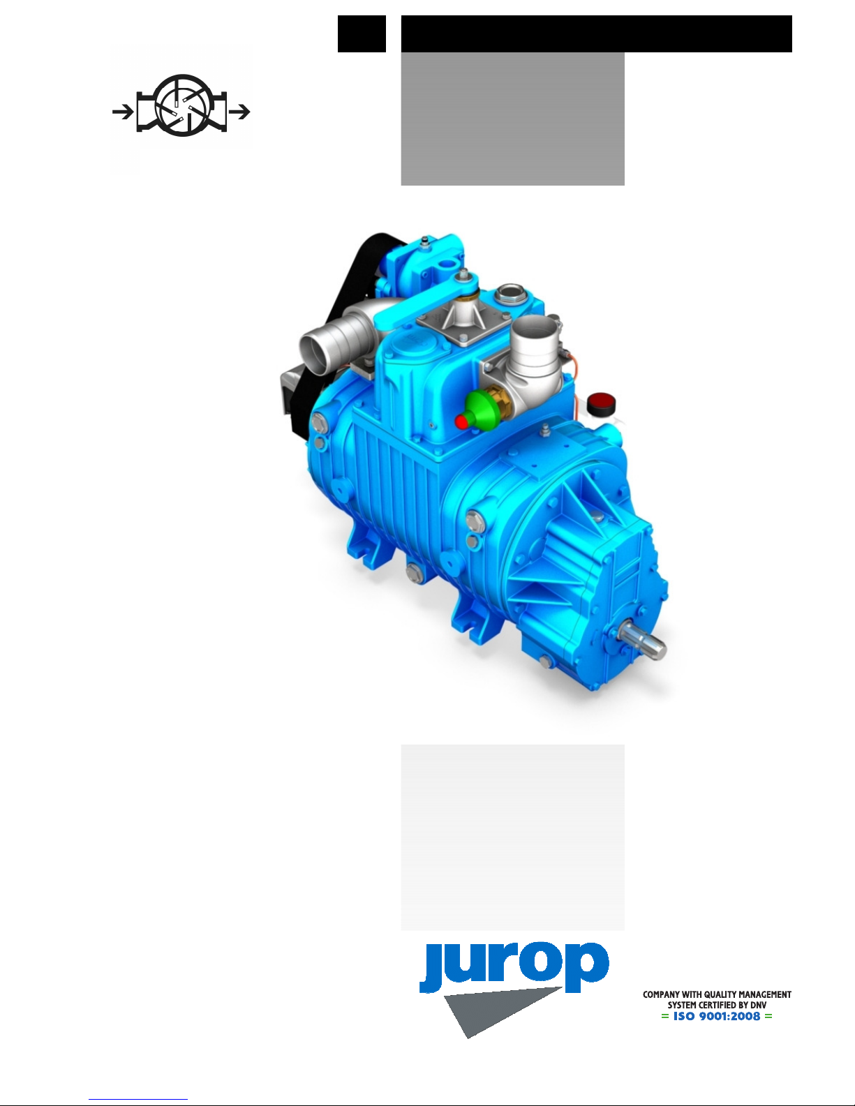
• Four-vane rotary pump with liquid cooled housing, suitable even for major duty operating
conditions with high volumetric efficiency and low noise. It has two inlet liquid points on the
lower part of its body and four outlet points on the upper part. They do not interfere with the
side mounted oil tank.
• Automatic lubricating pump, accessible from the outside for an easy and quick adjusting.
Copper oil piping, complete with sight glass drip oilers for a continuous check of the
lubrication system.
• Side mounted oil tank with level spy hole. The oil tank can be mounted either on the right
or left side of the pump to grant an easy oil checking and filling up. The outside mounting
of the oil tank grants a better cooling of the oil itself.
• Heavy duty vanes (asbestos free), radially disposed on the rotor: reduced wear for a long-
lasting lifetime. Vanes wear checking ports on the pump body: they do not interfere with the
side mounted oil tank.
• Built-in vacuum-pressure changeover 4-way valve, manually operated: on request,
hydraulic or pneumatic operated actuators available.
• Non return valve (rubber ball) integrated in the pump manifold
• Swivelling conveyors, made of aluminium alloy: various sizes available.
• Cooling water temperature: a mechanic thermometer can be inserted into one of the outlet
holes. A metal capillary operates the pointer that can be mounted on a visible point near the
pump. Delivered on request. Exhaust air temperature: the manifold is equipped
with a housing for the safety thermostat (intervention temperature: 150° C). Delivered on
request.
• Built-in suction air filter. It can be mounted horizontally whereas the suction hole can be
swivelled either towards the right or the left side, for an easy pump installation and the
following cleaning operations and maintenances. The space required to remove the inner
cartridge of the suction filter do not exceed the overall dimensions of the pump. Cleansing
agents suction points for the internal wash-up of the pump (recommended in case sewage
has been sucked).
• Drive system:
• Direct with smooth shaft
• With gear box (ASAE 1 3/8) 540 rpm o 1000 rpm, left rotation
• With hydraulic motor
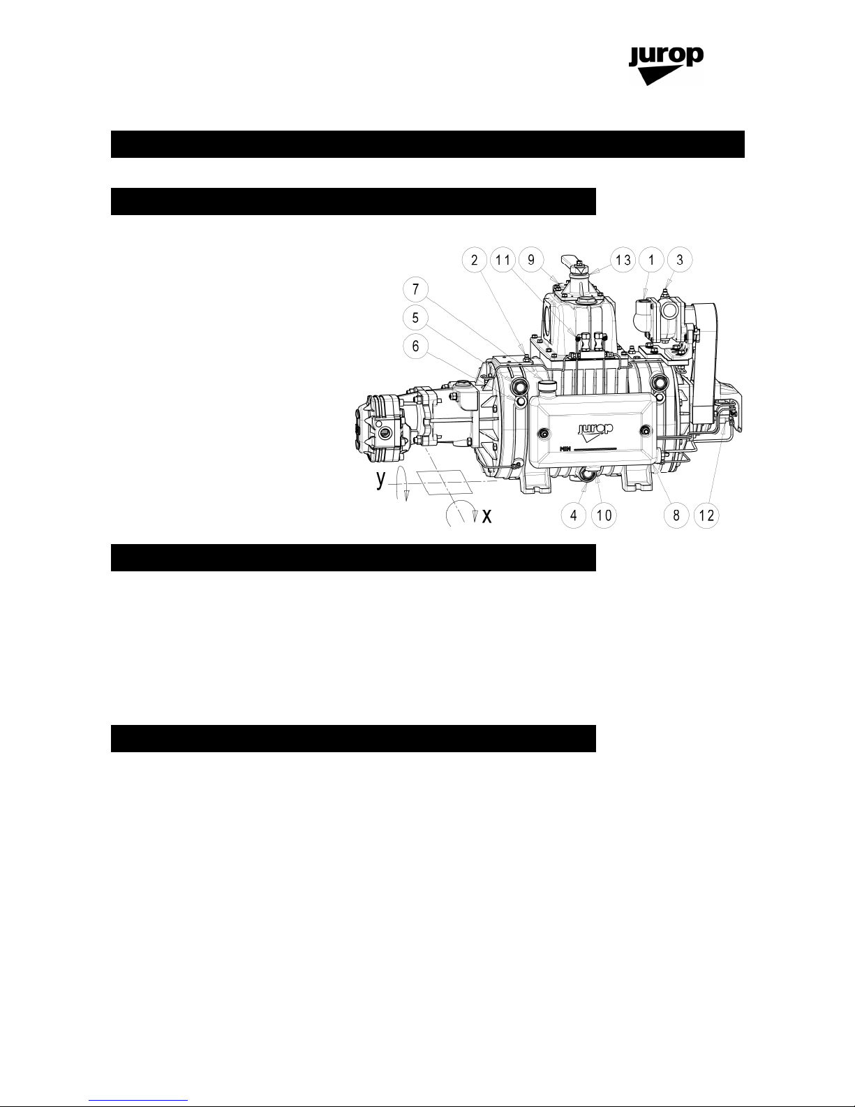
1. CONSTRUCTION FEATURES