http://www.jur p.it
e-mail: inf @jur p.it
Attenti n:
Carefully apply these prescripti ns.
3.1 General rec mmendati ns
• Installati n and maintenance must be carried ut with the unit
t tally disengaged fr m its drive system and must be perf rmed by
qualified pers nnel.
• Use adequate cl thing (av id ties, l se sleeves, necklaces and
s n) and suitable pr tecti n equipments (gl ves, pr tecti n glasses,
b ts...).
• T prevent err rs and hazard us situati ns, establish what each
perat r is resp nsible f r in the different maintenance perati ns.
• When transp rting the pump, use pr per slinging. St re the pump
in stable places.
• Make sure that all the parts f the unit are idle and c l, bef re
perf rming any maintenance perati n.
• Bef re each maintenance perati n, st p the pump and rest re
the atm spheric pressure.
• When the pump is running, s me parts may reach very high
temperatures (ab ve 100°C). Use all necessary precauti ns t av id
c ntact.
• Operat rs w rking nearby must av id pr l nged exp sure t the
n ise emitted by the aspirat r, if n t equipped with the pr per ear-
pr tecti n devices.
• Av id accidental sucti n f s lids: s lids may be pr jected at high
speed thr ugh the exhaust manif ld and cause injures. A filter must be
m unted n the suncti n line.
• D n t start the machine if the pr tecti n devices pr vided f r
transmissi ns are rem ved. Replace damaged parts.
• Pressure relief valve: p int the air flux away fr m the perat rs.
• D n t use the aspirat r ver its designed limits: the machine may
be damage and the perat r may be injured.
D n t exceed the p wer supply parameters
indicated in the technical tables (see par. 2.4).
3.2 Intended use
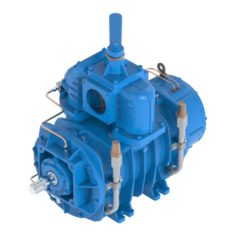
• The vacuum pumps RV are designed t c nvey filtered air int
systems f r the vacuum pr ducti n (example: systems f r the sucti n
f p wders r liquid wastes). Any ther usage shall be c nsidered
impr per.
• D n t sack t xic substances and inflammable r expl sive
gasses, since the internal c mp nents f the pump may reach high
temperatures.
• Liquids r s lids infiltrati ns can seri usly damage the pump.
• D n t run the pump ver its designed perating limits (see par.
2.4): it may break and transmissi n can be damaged.
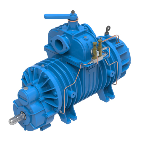
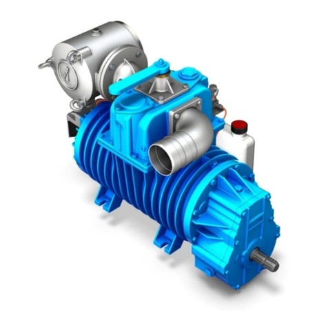
Legend f main c mp nents
1. Manif ld 5. Oil Tank 9. Lubricati n pump
2. Vacuum-pressure manif ld 6. Tank il stand 10.
