manuals.online logo
Brands
  1. Home
  2. •
  3. Brands
  4. •
  5. JVC
  6. •
  7. Car Stereo System
  8. •
  9. JVC KD-R524 Guide

JVC KD-R524 Guide

This manual suits for next models

1

Other JVC Car Stereo System manuals

JVC CS-VP528 User manual

JVC

JVC CS-VP528 User manual

JVC EXAD LVT1372-003A User manual

JVC

JVC EXAD LVT1372-003A User manual

JVC KD-LH1000R User manual

JVC

JVC KD-LH1000R User manual

JVC KD-HDW10J User manual

JVC

JVC KD-HDW10J User manual

JVC KD-X40 User manual

JVC

JVC KD-X40 User manual

JVC KD-T915BTS User manual

JVC

JVC KD-T915BTS User manual

JVC KD-G821 User manual

JVC

JVC KD-G821 User manual

JVC KD-G446 Guide

JVC

JVC KD-G446 Guide

JVC KD-LX100 User manual

JVC

JVC KD-LX100 User manual

JVC KD-R407 Guide

JVC

JVC KD-R407 Guide

JVC KD-G343 User manual

JVC

JVC KD-G343 User manual

JVC KW-ADV65BT User manual

JVC

JVC KW-ADV65BT User manual

JVC KW-R930BT User manual

JVC

JVC KW-R930BT User manual

JVC Model KW-XC400J User manual

JVC

JVC Model KW-XC400J User manual

JVC KD-G440 User manual

JVC

JVC KD-G440 User manual

JVC KD-X252 User manual

JVC

JVC KD-X252 User manual

JVC KD-R826BT Guide

JVC

JVC KD-R826BT Guide

JVC KS-fx270e Guide

JVC

JVC KS-fx270e Guide

JVC KD-G326 User manual

JVC

JVC KD-G326 User manual

JVC KS-FX742R User manual

JVC

JVC KS-FX742R User manual

JVC KD-SH9101 User manual

JVC

JVC KD-SH9101 User manual

JVC KD-DV5100 User manual

JVC

JVC KD-DV5100 User manual

JVC KD-AVX11 - EXAD - DVD Player Guide

JVC

JVC KD-AVX11 - EXAD - DVD Player Guide

JVC KD-R307 User manual

JVC

JVC KD-R307 User manual

Popular Car Stereo System manuals by other brands

Sony CDXM60UI - Marine CD Receiver MP3/WMA/AAC... Features

Sony

Sony CDXM60UI - Marine CD Receiver MP3/WMA/AAC... Features

Philips CED780/98 quick start guide

Philips

Philips CED780/98 quick start guide

Becker Online Pro 7800 installation guide

Becker

Becker Online Pro 7800 installation guide

Clarion PU-9836A Service manual

Clarion

Clarion PU-9836A Service manual

Sony RM-X7BT reference guide

Sony

Sony RM-X7BT reference guide

Mitsubishi Electric AR0M manual

Mitsubishi Electric

Mitsubishi Electric AR0M manual

Insignia NS-HD5113 user guide

Insignia

Insignia NS-HD5113 user guide

Clarion BTD3341 user manual

Clarion

Clarion BTD3341 user manual

USA SPECS PA11-VW6 owner's manual

USA SPECS

USA SPECS PA11-VW6 owner's manual

Sony MEX-N4380BT operating instructions

Sony

Sony MEX-N4380BT operating instructions

Kenwood KCD-BT6544U/UY Service manual

Kenwood

Kenwood KCD-BT6544U/UY Service manual

Philips CSQ405/98 user manual

Philips

Philips CSQ405/98 user manual

Alpine TDM-7544 Specifications

Alpine

Alpine TDM-7544 Specifications

JL Audio Stealthbox SB-CAN-G2MVX3D/10TW3 installation guide

JL Audio

JL Audio Stealthbox SB-CAN-G2MVX3D/10TW3 installation guide

Denso TEN FT0108A user manual

Denso TEN

Denso TEN FT0108A user manual

Pyle PLD57MU owner's manual

Pyle

Pyle PLD57MU owner's manual

Harman Chrysler Radio Navigation System RB4 user manual

Harman

Harman Chrysler Radio Navigation System RB4 user manual

Sony MEX-BT5750U operating instructions

Sony

Sony MEX-BT5750U operating instructions

manuals.online logo
manuals.online logoBrands
  • About & Mission
  • Contact us
  • Privacy Policy
  • Terms and Conditions

Copyright 2025 Manuals.Online. All Rights Reserved.

1
KD-R524/KD-R424
Installation/Connection Manual
0910DTSMDTJEIN
EN
© 2010 Victor Company of Japan, Limited
GET0703-002A
[UI]
Bracket *
Pocket
Flat head screws (M5 × 8 mm) *
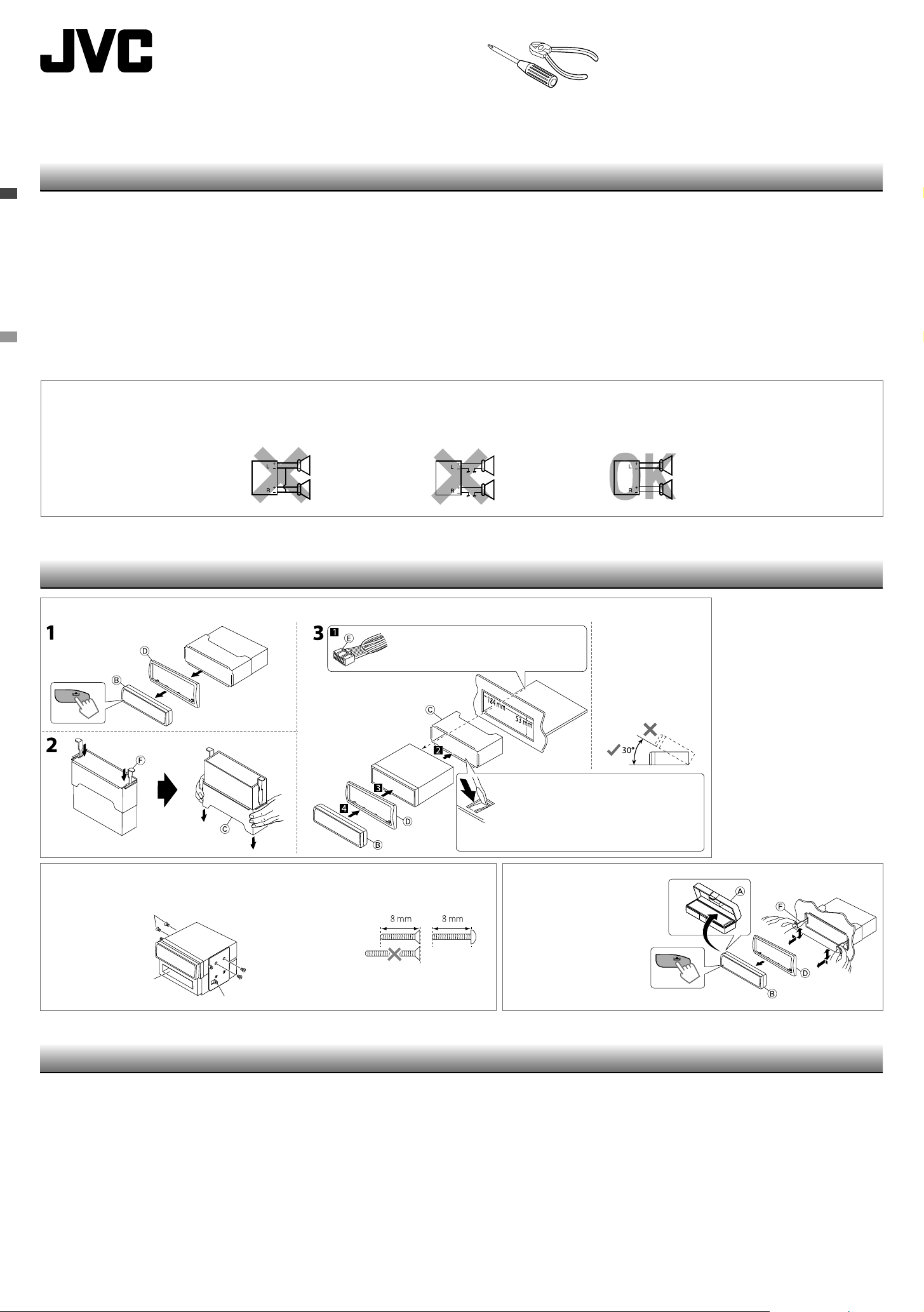
INSTALLATION
When installing the unit without using the sleeve
In-dash mounting
WARNINGS
Removing the unit
Release the rear section first...
Do the required electrical connections.
Bend the appropriate tabs to hold the sleeve
firmly in place.
Install the unit at an angle
of less than 30˚.
*Not supplied for this unit.
Part list
A
Hard case (×1)
B
Control panel (×1)
C
Sleeve (×1)
D
Trim plate (×1)
E
Power cord (×1)
F
Handles (×2)
• You need the installation kits which corresponds to your car.
• If you have any questions or require information regarding installation kits, consult your JVC car audio dealer or a company supplying kits.
• The unit can only be installed in a car with a 12 V DC power supply, negative ground.
• Disconnect the battery’s negative terminal and make all electrical connections before installing the unit.
• Connect speakers with a maximum power of more than 50 W (impedance of 4 Ω to 8 Ω). Otherwise, change the <AMP GAIN> setting. (See page 15 of the INSTRUCTIONS.)
• Insulate unconnected wires with vinyl tape or other similar material. To prevent a short circuit, do not remove the caps on the ends of the unconnected wires or the terminals.
• If the fuse blows, first make sure the wires are not touching to cause a short circuit, then replace the old fuse with one that has the same rating.
• Install this unit in the console of your vehicle.
• Mount the unit so that the mounting angle is 30° or less.
• Be sure to ground this unit to the car's chassis again after installation.
• After the unit is installed, check whether the brake lamps, blinkers, wipers, etc. on the car are working properly.
• Do not touch the metal part of this unit during and shortly after the use of the unit. Metal part such as the heat sink and enclosure become hot.
PRECAUTIONS on power supply and speaker connections
• DO NOT connect the speaker leads of the power cord to the car battery; otherwise, the unit will be seriously damaged.
• BEFORE connecting the speaker leads of the power cord to the speakers, check the speaker wiring in your car.
• The fuse blows.
]
Are the red and black leads connected correctly?
• Power cannot be turned on.
]
Is the yellow lead connected?
• No sound from the speakers.
]
Is the speaker output lead short-circuited?
• “MISWIRING CHK WIRING THEN RESET UNIT” appears on the display and no operation can be done.
]
Is the speaker output lead short-circuited or touches the chassis of the car/head unit? ; Have you reset your
unit?
• Sound is distorted.
]
Is the speaker output lead grounded? ; Are the “–” terminals of L and R speakers grounded in common?
• Noise interfere with sounds.
]
Is the rear ground terminal connected to the car’s chassis using shorter and thicker cords?
• This unit becomes hot.
]
Is the speaker output lead grounded? ; Are the “–” terminals of L and R speakers grounded in common?
• This unit does not work at all.
]
Have you reset your unit?
TROUBLESHOOTING
Install_KD-R524[UI]f.indd 1Install_KD-R524[UI]f.indd 1 10/5/10 9:14:05 AM10/5/10 9:14:05 AM
2
Black
Black
Fuse block
Ignition switch
Blue
Blue (white stripe)
Vehicle-specific Wiring Harness
(separately purchased)
Yellow
For your reference:
Metra Electronics:
www.metraonline.com
Scosche Industries:
www.scosche.com
Front speaker (left)
White
White (black stripe)
Front speaker (right)
Gray
Gray (black stripe)
Rear speaker (left)
Green
Green (black stripe)
Rear speaker (right)
Purple
Amp Turn-on (200 mA max.)
Red
12 V Ignition Switch
12 V Battery
Ground
Illumination
Telephone Muting
Purple (black stripe)
Signal cord* 1
Extension lead*1
Remote lead
Rear ground terminal 10 A fuse
Antenna terminal
*1Not supplied for this unit.
*2Firmly attach the ground wire to the metallic body or to the chassis of the car—to the place uncoated with paint.
*3Make the <L/O MODE> setting accordingly, see page 14 of the INSTRUCTIONS.
ELECTRICAL CONNECTIONS
Reset the unit.
JVC Amplifier
Recommended connection
Connecting the Bluetooth adapter or portable audio player
Orange (white stripe)
Brown
Brown To the brown lead of the supplied power cord
E
To the blue (white stripe) lead of the supplied power cord
E
Ground
E
Power cord
– – – – – – – – – – – – – – – – – – – – – – – – – – – – – – – – – – – – – – – – or – – – – – – – – – – – – – – – – – – – – – – – – – – – – – – – – – – – – – – – –
KS-BTA100
(separately purchased)
Portable audio player, etc.* 1
3.5 mm stereo mini plug* 1
Make the <SRC SELECT> setting accordingly, see
pages 9, 15, and 18 of the INSTRUCTIONS.
If your vehicle factory wiring harness does not
have “12 V ignition switch” lead, connect the
red lead of the supplied power cord,
E
, to the
vehicle fuse block (through a separate red lead
provided with the fuse tap).
Factory wiring harness (vehicle)
Power cannot be turned on?
Separate red lead
Caution
Blue (white stripe)
Automatic antenna (250 mA max.)
KD-R524:
FRONT : To front speakers
REAR/SW : To rear speakers or subwoofer *3
– – – – – – – – – – – – – – – – – – – – – – – – – – – –
KD-R424:
REAR/SW : To rear speakers or subwoofer *3
Strip lead ends
Twist ends together
Solder
Tape
Join the same color leads together.
To join the open-ends of the leads:
Remote adapter*1Blue (yellow stripe)
KD-R524
Install_KD-R524[UI]f.indd 2Install_KD-R524[UI]f.indd 2 10/5/10 9:14:06 AM10/5/10 9:14:06 AM