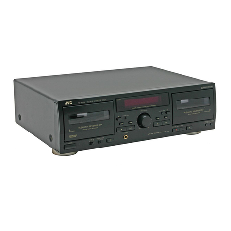
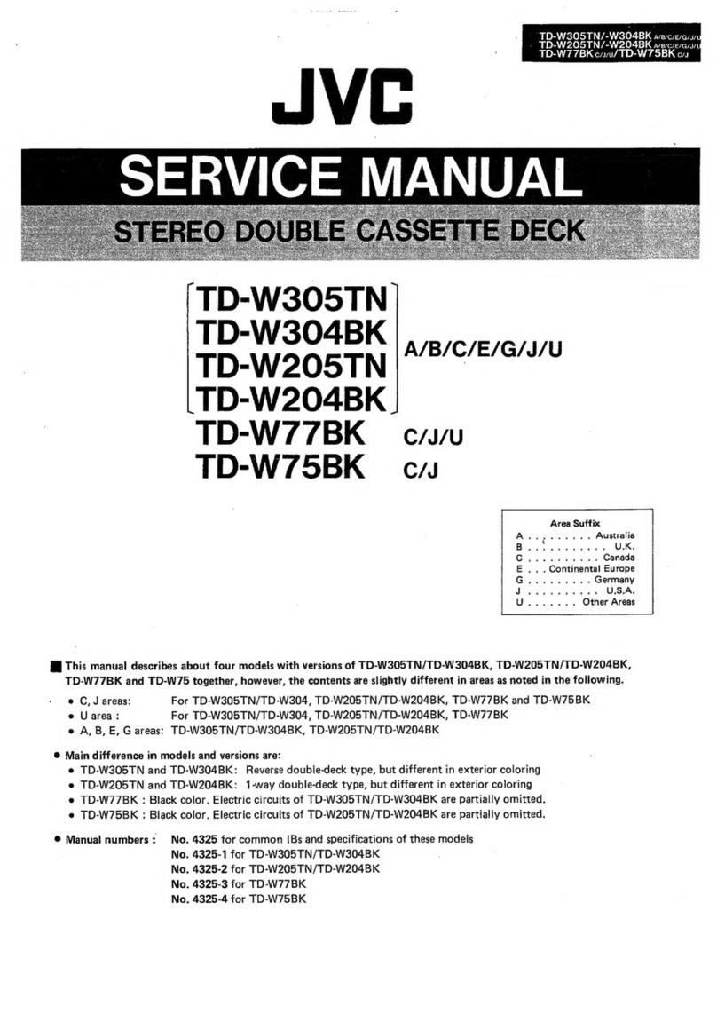
JVC PC-Y777 B User manual

PC-Y777
B/E/G
=
SERVICE
MANUAL
PC-Y777
sec
Ss
ao
OO
SS
SRE
sae
Sx
ws
SS
vs
2x
8
e,
REX
XS
ie
KR
b
Area
suffix
Boteesy
axesed
ad
UK
EB
sicsaennectee
Continental
Europe
G)
Saati
ceee
West
Germany
Contents
Page
Page
[1]
Safety
Precautions
...............ccccceenee
eee eec
teen
een
eeeee
2
Standard
Schematic
Diagram
......................0600
19
Safety
Precautions
about
PC-Y777
...............:45
3
[11]
Wiring
Connections
............:ccceeeeeeesesseeeeneenens
21
Features
.........ecceseceecnesecseeeeeseeceesentetenesereceeoees
4
Location
of
P.C.
Board
and
Parts
List
................
22
[4]
Specifications
2.0.0.0...
ccc
cece
ce
cece
cence
tent
en ee
eeeeeees
4
[13]
Exploded
View
of
Mechanism
Component
[5]
Name
of
Controls
and
Their
Functions
..............-
5
and
Parts
List
2.2.0.0...
cece
eee
nese
eee
ee
eee
rere
eeeeenene
28
[6]
Location
of
Main
Parts
...........cccceeseeeseeneeetees
7
Exploded
View
of
Enclosure
Assembly
Removal
of
Main
Parts
................ccececeeeeee
eee
eens
10
and:
Parts
List
o.cci0iccctscadewiiv
ected
qetasavae
seeders
saci
30
Main
Adjustments
.................cccceeeeeeeceeeeeeeeeeeees
12
[15]
Packing
Illustration
and
Packing
Parts
List
.........
34
[9]
Block
Diagram
..............c
cece
ccc
cc
nee
ee
eee
e
neces
eeeeee
18
No.
1802
July
1990

PC-Y777
B/E/G
|
2
~|1|
Safety
Precautions
1.
The
design
of
this
product
contains
special
hardware
and
many
circuits
and
components
specially
for
safety
purposes.
For
continued
protection,
no
changes
should
be
made
to
the
original
design
uniess
authorized
in
writing
by
the
manufacturer.
Replacement
parts
must
be
identical
to
those
used
in
the
original
circuits.
Service
should
be
performed
by
qualified
personnel
only.
2.
Alterations
of
the
design
or
circuitry
of
the
product
should
not
be
made.
Any
design
alterations
of
the
product
should
not
be
made.
Any
design
alterations
or
additions
will
void
the
manufacturer’s
warranty
and
will
further
relieve
the
manufacturer
or
responsibility
for
personal
injury
or
property
damage
resulting
therefrom.
3.
Many
electrical
and
mechanical
parts
in
the
product
have
special
safety-related
characteristics.
These
characteristics
are
often
not
evident
from
visual
inspection
nor
can
the
protection
afforded
by
them
necessarily
be
obtained
by
using
replacement
components
rated
for
higher
voltage,
wattage,
etc.
Replacement
parts
which
have
these
special
safety
characteristics
are
identified
in
the
Parts
List
of
Service
Manual.
Electrical
components
having
such
features
are
identified
by
(A\)
on
the
schematic
diagram
and
Parts
List
in
Service
Manual.
The
use
of
a
substitute
replacement
which
does
not
have
the
same
safety
characteristics
as
the
recommended
replace-
ment
part
shown
in
the
Parts
List
in
Service
Manual
may
create
shock,
fire,
or
other
hazards.
4.
The
leads
in
the
products
are
routed
and
dressed
with
ties,
clamps,
tubings,
barriers
and
the
like
to
be
separated
from
live
parts,
high
temperature
parts,
moving
parts
and/or
sharp
edges
for
the
prevention
of
electric
shock
and
fire
hazard.
When
service
is
required,
the
original
lead
routing
and
dress
should
be
observed,
and
it
should
be
confirmed
that
they
have
been
returned
to
normal,
after
re-assembling.
5.
Leakage
current
check
(Electrical
shock
hazard
testing)
After
re-assembling
the
product,
always
perform
an
isolation
check
on
the
exposed
metal
parts
of
the
product
(antenna
terminals,
knobs,
metal
cabinet,
screw
heads,
headphone
jack,
control
shafts,
etc.)
to
be
sure
the
pro-
duct
is
safe
to
operate
without
danger
of
electrical
shock.
Do
not
use
a
line
isolation
transformer
during
this
check.
*
Plug
the
AC
line
cord
directly
into
the
AC
outlet.
Using
a
‘Leakage
Current
Tester’’,
measure
the
leakage
current
from each
exposed
metal
part
of
the
cabinet,
particularly
any
exposed
metal
part
having
a
return
path
to
the
chassis,
to
a
known
good
earth
ground.
Any
leakage
current
must
not
exceed
0.5
mA
AC
(r.m.s.).
®
Alternate
check
method
Plug
the
AC
line
cord
directly
into
the
AC
outlet.
Use
an
AC
voltmeter
having
1,000
ohms
per
volt
or
more
sensitivity
in
the
following
manner.
Connect
a
1,500
2
10
W
resistor
paralleled
by
a
0.15
uF
AC-type
capacitor
between
an
exposed
metal
part
and
a
known
good
earth
ground.
Measure
the
AC
voltage
across
the
resistor
with
the
AC
ET
Were
ons
cea
voltmeter.
or
more
sensitivity.)
Move
the
resistor
connection
to
each
exposed
metal
o
Sl
part,
particularly
any
exposed
metal
part
having
a
return
.
0.15
pF
AC
TYPE
path
to
the
chassis,
and
measure
the
AC
voltage
across
the
resistor.
Now,
reverse
the
plug
in
the
AC
outlet
and
‘
Blake
thiscorebe
repeat
each
measurement.
Any
voltage
measured
must
on
each
etpcaad
not
exceed
0.75
V
AC
(r.m.s.).
1500
2
10
W
metal
part.
This
corresponds
to
0.5
mA
AC
(r.m.s.).
Good
earth
ground
—Warning
.
This
equipment
has
been
designed
and
manufactured
to
meet
international
safety
standards.
.
It
is
the
legal
responsibility
of
the
repairer
to
ensure
that
these
safety
standards
are
mainteined.
.
Repairs
must
be
made
in
accordance
with
the
relevant
safety
standards.
.
It
is
essential
that
safety
critical
components
are
replaced
by
approved
parts.
.
If
mains
voltage
selector
is
provided,
check
setting
for
local
voltage.
oh
WON
=
(No.
1802)

|
PC-Y777
B/E/G
Safety
Precautions
about
PC-Y777
PRECAUTIONS
Prevention
of
damage
to
the
set
1.
Do
not
leave
this
unit
in
direct
sunlight
or
in
extremely
hot
(about
40°C
(104°F))
or
humid
places
or
in
closed
automobiles
in
the
sun.
2.
Exhausted
batteries
in
the
unit
may
cause
damage
due
to
corrosion.
When
the
unit
is
not
used
for
more
than
2
weeks,
remove
the
batteries.
3.
Never
use
benzine
or
thinner
for
cleaning
as
these
will
damage
the
cabinet.
4.
Place
the
unit
as
far
away
from
the
TV
as
possible.
Prevention
of
electric
shock
and
fire
hazards
1.
Even
when
the
POWER
switch
is
set
to
STANDBY,
a
very
small
current
will
flow.
To
save
power
and
for
safety
when
not
using
the
unit
for
an
extended
period
of
time,
disconnect
the
power
cord
from
the
household
AC
outlet.
2.
Do
not
handle
the
power
cord
with
wet
hands.
3.
When
unplugging
the
power
cord,
always
grasp
and
pull
the
plug,
not
the
power
cord.
CAUTION:
|
TO
REDUCE
THE
RISK
OF
ELECTRIC
SHOCK,
4,
Consult
your
nearest
dealer
when
damage,
disconnection
|
DO
NOT
REMOVE
COVER
(OR
BACK).
or
contact
failure
is
found
with
the
cord.
NO
USER-SERVICEABLE
PARTS
INSIDE.
REFER
SERVICING
TO
QUALIFIED
SERVICE
PERSONNEL.
The
lightning
flash
with
arrowhead
symbo!,
The
exclamation
point
within
an
equilateral
within
an
equilateral
triangle,
is
intended
to
triangle
is
intended
to
alert
the
user
to
the
alert
the
user
to
the
presence
of
uninsulated
Presence
of
important
operating
and
main-
“dangerous
voltage”
within
the
product's
tenance
(servicing)
instructions
in
the
litera-
enclosuré
that
may
be
of
sufficient
magni-
ture
accompanying
the
appliance.
tude
to
constitute
a
risk
of
electric
shock
to
persons.
B
Important
management
points
regarding
safety
A
@
(version
‘
only
z
(Items
Demanding
Special
Safety
Precautions)
gaat
:
1.
Make
sure
that
the
soldering
round
does
not
protrude
in
order
to
maintain
a
gap
between
the
primary
circuit
of
the
circuit
board
and
the
pattern
adjoining
the
primary
circuit.
2.
Confirm
that
the
power
transistor
is
provided
with
the
parts
number
‘’VTP57P2-12C/VTP57P2-12CBS"’,
and
to
prevent
the
pattern
from
coming
off,
confirm
that
the
fixation
screw
for
the
circuit
board
is
not
loose.
3.
Confirm
that
the
AC
socket
is
provided
with
the
number
“HSC
1466"
and
that
the
pattern
is
properly
fixed.
4,
Check
that
clamping
has
been
properly
performed
to
pre-
vent
contact
with
heated
parts.
5.
As
D999,
the
heat
sink
IC801,
802,911,
R751, R761,
R723,
R814,
R815,
R28,
Q914
and
0916
are
heated
parts,
make
sure
that
they
do
not
come
in
contact
with
the
wire
and
the
E.
cap.
6.
Confirm
that
fuses
F998
and
F997
‘’T4A”
“’250”
are
properly
maintained,
and
that
the
volume
indication
seal
‘
DTS
Board
ae co
aed
Tuo
d
T4A/125"
is
attached
next
to
the
fuse.
‘aprenne
oe
aes
Ti
Ts
7.
In
order
to
prevent
the
tuner
wire
from
contacting
the
Wire
primary
fuse,
check
that
the
wire
is
inseted
into
the
rib
and
that
it
is
fastened
with
bond.
8.
Make
sure
that
all
support
parts
are
bonded
and
fixed
with
spacers.
Amp
Board
(No.
1802)
3

PC-Y777
B/E/G
|
4
Features
1.
MW/LW/FM-stereo
PLL
synthesizer
tuner.
@
20-station
preset
tuning
(FM-10,
MW-5,
LW-5).
@
Seek/manual
tuning.
2.
Double-cassette
mechanism
(Deck
A
for
recording
and
playback,
Deck
B
for
playback).
¢
Dolby*B
Noise
Reduction
system.
Metal
and
CrO,
tape
can
be
played
back
for
superior
tone
quality.
Synchro
start
dubbing
function
(normal/high
speed
dubbing).
e
Relay
playback
(from
Deck
B
to
Deck
A).
3.
“LIVE
EFFEX”
Sound
System
for
the
reproduction
of
an
expanded
sound
field.
4.
Hyper-Bass
Sound
System
with
3D
super
woofer.
.
5-Band
graphic
equalizer
(S.E.A.)
controls.
.
CD
IN
jacks.
ac
*
Dolby
noise
reduction
manufactured
under
license
from
Dolby
Labo-
ratories
Licensing
Corporation.
“DOLBY”
and
the
double-D
symbol
[]{Jare
trademarks
of
Dolby
Labo-
ratories
Licensing
Corporation.
4]
Specifications
<Radio
Section
>
Frequency
:
FM
87.5—
108
MHz
PC-Y777
B
ranges
AM
522—1,629
kHz
e
FM
=
87.5—108
MHz
MW
=
522-—-1,629
kHz
-
SW
6—18
MHz
i
a
LW
144—288
kHz
FM
87.5—108
MHz
MW
=
522—1,629
kHz
:
SW
6—18
MHz
POMEL
LW
144—288
kHz
Antennas
:
Telescopic
antenna
for
FM
Ferrite
core
antenna
PC-Y777
B
for
AM
Telescopic
antenna
ina
eia
ante
(PC-Y777
E/G)
Ferrite
core
antenna
MW
&
LW
<Tape
Recorder
Section>
Track
system
:
4-track
2-channel
stereo
Frequency
:
40—14,000
Hz
response
(with
normal
tape)
Wow
&
flutter:
0.15%
(WRMS)
Fast
wind
time:
Approx.
120
sec.
(Deck
A:
C-60
cassette)
Approx.
120
sec.
(Deck
B:
C-60
cassette)
<General
>
3D
system
:
ASW
(Acoustic
Super
Woofer)
Power
output
10W
(5W
+
5W)
at
62
and
13
W
for
3D
at
8
Q
(Max.)
6
W
(3
W
+
3W)
at
62
and
7
W
for
3D
at
8
Q
(10%
THD)
S.E.A.
:
S.E.A.
center
frequencies:
characteristics
100
Hz/330
Hz/1
kHz/3.3
kHz/
10
kHz
S.E.A.
control
range:
+10
dB
(No,
1802)
“LIVE
EFFEX"”
Sound
System
When
stereo
sources
are
heard
from
the
speakers,
often
the
sound
feels
far
more
restricted
than
in
a
live
performance.
This
is
because
the
stereo
effect
is
degraded
due
to
crosstalk**
between
our
left
and
right
ears.
The
PC-Y999/Y777
removes
this
acoustic
cross-
talk
between
the
ears
using
our
newly
developed
“LIVE
EFFEX”
signal
sound
processor;
with
this,
the
sound
image
extends
beyond
the
speakers,
realizing
a
natural
stereo
sound
field.
**
Crosstalk
is
a
phenomenon
in
which
sound
from
two
channels
is
mixed;
in
addition
to
hearing
sound
from
the
right
speaker,
the
right
ear
hears
sound
from
the
left
speaker,
with
a
slight
time
delay.
Input
jacks
Output
jacks
:CD
IN
xX
2
(440
mV/50
kQ)
:
Speaker
x
2
(Matching
im-
pedance
6
—
16
)
Headphones
x
1
(15
mW/32
Q,
Matching
impedance
16
2—1
kQ)
:
DC
12
V
(8’°R20"'
batteries)
AC
240
V,
50
Hz
(PC-Y777
B)
AC
220
V,
50 Hz
(PC-Y777
E/G)
Ext.
DC
IN
12
V
(Car
battery
via
optional
CN-332
car
adapter)
Power
consumption
:
36
W
(with
POWER
SW
ON)
2.0
W
(with
POWER
SW
STANDBY)
:
650(W)
x
235(H)
x
235(D)
mm
including
knob
Power
supply
Dimensions
Weight
:
Approx.
6.9
kg
(without
batteries)
<
Speaker
Section
>
(each
unit)
Speaker
:10cmx
1
Impedance
7:60
Dimensions
:
155(W)
x
215(H)
x
195(D)
mm
Weight
:
Approx.
1.1
kg
Design
and
specifications
subject
to
change
without
notice.

|
PC-Y777
B/E/G
[5]
Name
of
Controls
and
Their
Functions
@
Front
panel
@
Top
panel
@
Rear
panel
@
Display
window
©
indicators
(for
tuner
operation)
BAND
indicator
(FM1-FM2-MW-LW)
Radio
frequency
display
Preset
station
indicator
STEREO
(FM
stereo)
indicator
@
BAND
button
©
Tuning
control
DOWN
frequency
UP
frequency
©
Preset
station
buttons
Cassette
holder
(Deck
A)
Cassette
hoider
(Deck
B)
@
VOLUME
contro!
®
Cassette
operation
buttons
(Deck
A)
O
REC:
Press
this
button
with
the
B®
PLAY
button
for
re-
cording.
bm»
PLAY:
Press
to
play
the
tape.
@<REW:
Press
to
rewind
the
tape
rapidly.
PP
rF:
Press
to
wind
the
tape
forward
rapidly.
m/SSTOP/EJECT:
Press
to
stop
the
tape.
Pressing
this
button
after
the
tape
stops
opens
the
cassette
holder.
SUPAUSE:
Press
to
stop
the
tape
temporarily.
Press
again
to
release
the
pause
mode.
@
HYPER-BASS
switch
and
3D
indicator
-m=
ON:
Set
to
this
position
to
listen
to
Hyper-Bass
Sound.
OFF:
Set
to
this
position
when
Hyper-Bass
Sound
is
not
required.
®
This
function
does
not
work
while
headphones
are
being
used.
@
LIVE
EFFEX
switch
and
LE
indicator
wm.
ON:
Set
to
this
position
to
listen
to
the
LIVE
EFFEX
sound.
OFF:
Set
to
this
position
when
the
LIVE
EFFEX
sound
is
not
required.
(No.
1802}
5
ih
si
pales
es
rh
ai
igen
ce
eiladllintadtin

PC-Y777
B/E/G
6
@®
Cassette
operation
buttons
(Deck
B)
>
PLAY:
Press
to
play
the
tape.
@<REW:
Press
to
rewind
the
tape
rapidly.
PPFF:
Press
to
wind
the
tape
forward
rapidly.
@/SSTOP/EJECT:
;
Press
to
stop
the
tape.
Pressing
this
button
after
the
tape
stops
opens
the
cassette
holder.
@
TAPE
(FOR
PLAYBACK)/FM
MODE
switch
TAPE
(FOR
PLAYBACK)
:
Set
this
switch
according
to
the
type
of
tape
to
be
used.
«m=.
METAL/CrO,
:
(Playback
only)
Set
to
this
position
to
listen
to
a
metal
(type
IV)
or
chrome
(type
II}
tape.
NORMAL:
Set
to
this
position
to
listen
to
a
normal
(type
|)
tape.
FM
MODE
switch:
-=
MONO:
Set
to
this
position
when
FM
stereo
reception
is
obscured
by
noise.
STEREO:
Set
to
this
position
when
listening
to
or
recording
an
FM
stereo
broadcast.
@
DOLBY
NR
switch
Set
to
ON
{
«=m
)
when
recording
or
playing
back
tapes
using
the
noise
reduction
system.
CONNECTIONS
@
Do
not
switch
the
power
on
until
all
the
connections
are
completed.
FM
outdoor
antenna
@
Headphones
jack
(PHONES)
(3.5
mm
dia.
stereo
mini
jack)
Connect
headphones
(impedance
1692
—
1k)
to
this
jack,
The
speakers
are
automatically
switched
off
when
headphones
are
connected.
@
POWER
switch
@
FUNCTION
switch
TAPE-NORMAL
SPEED
DUBBING:
Set
to
this
position
when
listening
to
a
cassette
or
dub-
bing
at
normal
speed.
TAPE-HIGH
SPEED
DUBBING:
Set
to
this
position
when
dubbing
at
high
speed.
TUNER:
Set
to
this
position
when
listening
to
or
recording
from
the
radio.
CD
IN:
Set
to
this
position
when
listening
to
or
recording
from
the
source
connected
to
the
CD
IN
jacks.
5-BAND
GRAPHIC
EQUALIZER
controls
(S.E.A.)
Memory
backup
battery
compartment
cover
Telescopic
antenna
for
FM
reception
BEAT
CUT
switch
EXT
ANT
terminal
for
FM
(PC-Y999E/Y777E)
@
CD
IN
jacks
Connect
a
CD
player.
@
SPEAKER
terminals
Connect
the
provided
speakers
to
these
terminals.
@
AC
IN
(AC
input)
jack
@®
DC
IN 12
V
jack
(
--®—+
)
(PC-Y999E/Y777E)
@)
Battery
compartment
cover
Signal
cord
provided
with
the
CD
player
{
To
LINE
OUT
jacks
CD
player
(optional)
*
Space
for
speaker
cords
After
connecting
the
speaker
cords,
bundle
any
slack
into
the
space
for
the
speaker
cords
in
the
rear
panel.
@
When
connecting
the
speaker
cords,
connect
the
one
marked
with
a
jine
to
the
‘-”
ter-
minal
first.
—)
®
Marked
with
line
Notes:
1,
Connect
the
connection
cords,
etc,
being
sure
not
to
confuse
channels
or
polarities.
The
wrong
connection
will
degrade
the
sound
quality
and
stereo
effect.
2.
Be
sure
to
connect
the
connection
cords,
etc.
correctly.
Otherwise,
there
will
be
no
sound
or
there
will
be
noise.
(No.
1802)

PC-Y777
B/E/G
o|
Location
of
Main
Parts
Speaker
terminal
Main.
board
CD
IN
jack
©,
Tuner
board
DC
IN
12.
V
Fig.
6-1
Beat
cut
switch
CD
IN
Beat
cut
switch
SEA
board
Tuner
board
TT
i
Main
board
Fig.
6-2
(No.
1802)
7

PC-Y777
B/E/G
|
DTS
board
ass’y
Mechanism
ass’y
Fig.
6-3
Graphic
equalizer
ass’y
Fig.
6-4
8
(No.
1802)

U
o)
1
~<
~J
si ie
wo
mi
Go)
~
Mechanism
[Al
~
~
Mechanism
[B]
~
RF
clutch
ass’y
RF
clutch
ass’y
t
Supply
reel
disk
Take
up
reel
disk
Supply
reel
disk
Take
up
reel
disk
\
CO.
os
|
A
|
|
Erase
head
Rec./playback
head
Main
belt
Playback
head
Fig.
6-5
Motor
ass’y
RF
clutch
ass’y
RF
clutch
ass'y
1
|
|
Flywheel
assy
P.
Kick
lever
(A)
Flywheel
ass’y
Fig.
6-6
(No.
1802)
9

PC-Y777
B/E/G
|
Removal
of
Main
Parts
@
Rear
Cover
1.
Remove
the
battery
cover
(main
battery).
2.
Remove
the
three
screws
@)
retaining
the
RCA
jack
and
top
side
of
the
rear
cover.
3.
Remove
the
five
screws
Q)
retaining
the
rear
cover
from
the
backside.
4.
Remove
the
two
screws
(3)
rataining
the
rear
cover
in
the
battery
box.
5.
Slightly
pull
out
the
rear
cover
and
remove
the
memory
battery
and
the
antenna
wire.
Memory
battery
.....
Preamplifier
circuit
board
Antenna
wire
.........
Tuner
board
@
Tuner Board
Assembly
1.
remove
the
connector
(CN3)
and
the
flat
wire
(CN1)
from
the
DTS
board.
2.
Remove
the
output
cord
from
CN3
of
the
preamplifier
board.
3.
Pull
out
the
tuner
board
assembly.
ks
|
Fig.
7-1
Function
knob
B
Graphic
Equalizer
Assembly
(SEA
assembly)
1.
Pull
the
G.
equalizer
assembly
rearward
and
remove
the
cabinet.
2.
Remove
the
connection
wire
from
CN703
of
the
preamplifier
board.
3.
Remove
the
one
screw
retaining
the
G.
equalizer
board
assembly.
i
:
i
|
3
]
!
{
|
.
@
3D
Assembly
(with
pre-
and
power
board
assemblies)
1.
Remove
the
function
switch
knob.
2.
Remove
the
one
screw
(4)
located
under
the
function
knob.
3.
Remove
the
one
screw
6)
retaining
the
right
side
of
the
cabinet.
4.
Pull
out
the
volume
knob.
.
Remove
the
two
screws
1)
under
the
3D
case.
6.
Release
the
head
wire
and
the
motor/switch
wire
from
the
preamplifier
board.
Motor/switch
wire
Power
amplifier
board
CN802
B.
mechanism
Back
view
oa
Preamplifier
CN701
Remove
the
head
wire
A.
mechanism
connector
.
Preamplifier
CN702
if
necessary
head
wire
7.
Pull
out
the
3D
assembly.
Preamplifier
Board
Assembly
1.
Remove
the
four
screws
6)
retaining
the
preamplifier
board.
2.
Remove
the
board
assembly
wire.
CN804
to
the
power
board.
CN707
to
the
preamplifier
board.
10
(No.
1802)

@
Power
Amplifier
Board
1.
Remove
the
two
screws
®
retaining
the
power
transformer
bracket.
2.
Remove
the
one
screw
retaining
the
power
amplifier
board.
3.
Remove
the
Mono/ST.
switch
board
and
the
circuit
board
or
remove
screw
4.
Remove
the
3D
connector
(CN801).
5.
Remove
the
circuit
board
knob
part
of
the
volume
assembly
and
pull
it
out
in
forward
direction.
6.
remove
the
two
screws
retaining
the
LE
(Live
Effex)/3D
switch
board.
M
3D
Speaker
1.
Remove
the
four
screws
retaining
the
circuit
board
chassis.
(Under
the
preamplifier
board)
2.
Remove
the
six
screws
retaining
the
3D
cabinet.
(Five
from
the
rear
and
one
from
the
front)
@
Mechanism
Assembly
1.
Remove
the
one
screw
retaining
the
recording
arm.
2.
Remove
the
six
screws
a2
and
a3
retaining
the
mechanism
assembly.
m@
DTS
Board
Assembly
1.
Remove
the
10
screws
and
a8
retaining
the
DTS
board.
i
>
4
Pull
out
the
circuit
board
assembly
while
pulling
the
knob
in
the
direction
of
the
arrow.
PC-Y777
B/E/G
Fig.
7-5
(
@ @
()
Qe)
DTS
board
Fig.
7-6
(No.
1802)
11

PC-Y777
B/E/G
|
Main
Adjustments
@
Equipment
and
Measuring
Instrument
used
for
Adjustments
Electronic
voltmeter
Audio
frequency
oscillator
Attenuator
Wow-flutter
meter
Frequency
counter
BH
Condition
for
Measurement
Power
Supply
......
AC
240
V
(50
Hz):
PC-Y777
B
AC
220
V
(50
Hz):
PC-Y777
E/G
DC
12
V:
PC-Y777
B/E/G
Reference
output
..
Speaker
:
0
dBs
(0.55
V)/6
Q
Headphone:
—
13
dBs
(0.173
V)/32
Q
Reference
input.....
Ext.
MIC
:
—46
dBs
H@
Condition
for
Measurement
:
Tuner
Section
Applied voltage
of
the
Tuner
:
DC
5.8
V
Reference
output
:
Speaker
;
50
mW
(0.55
V)/6
Q
Input
signal
:
(AM)
Modulation
frequency;
400
Hz,
30%
(FM)
Modulation
frequency;
400
Hz
22.5
kHz
dev.
Set
position
of
Volume
and
Switch
:
SEA;
VOLUME;
Center
Dummy
antenna
for
short
wave.
Lod
length
‘cm
L>90
902=L2=60
L<60
C1
(PE)
10
8
6
R1+R2=802
R1
:
Output
impedance
of
SSG.
Fig.
8-1
@
Preset
Memory
(Initialize)
Standard
signal
generator
Torque
testing
cassette
gauge
CTG-N
Alignment
tape
Measuring
tape:
TS-12
(UR)
VTT702
(8
kHz)
Function
position
..
TAPE/FM
MODE:
TAPE
NORMAL
FUNCTION
:
NORMAL
SPEED
SEA
:
Center
VOLUME
:
Center
BEAT
CUT
:
NORMAL
Attentive
point
Connection
of
IF
sweeper:
Connect
a
30
pF
capacitor
and
a
33
kQ
resistor
in
series
to
the
sweeper’s
output
while
0.082
pF
capacitor
and
a
100
kQ
resistor
in
parallel
to
the
input.
IF
sweeper’s
output
level:
Set
as
minimum
as
enough
for
adjustment.
FM
MPX
adjustment:
For
this
adjustment,
connect
a
100
kQ
resistor
in
series
to
a
frequency
counter’s
input.
Loop
Antenna
AM
SSG
LOOP
ANTENNA
60cm
'
Fig.
8-2
BAR
ANT.
BAND
M1
M2
|
M3
M4
|
M5
AM
(kHz)
530
600
1000
1500
|
530
FM
(MHz)
87.5
88
|
98
106
|
87.5
12
(No.
1802)

AM
IF
Alignment
and
Check
PC-Y777
B/E/G
(The
unit
should
not
usualy
require
adjustment.
Foliow
the
steps
below
when
adjustments
are
necessary.)
1.
Band
select
switch
+
AM
or
MW
|
Adjusting
parts
T2
Alignment
methode
2.
Tuning
position
Near
the
highest
frequency
position
where
no
signal
come
in.
[
3.
Volume
control
Minimum
gain
position.
4.
IF
input
Positive
side
to
TP3.
5.
IF
output
Positive
side
to
TP6,
Negative
side
to
TP7.
6.
7.
Adjust
above
mentioned
aligning
position
so
that
maximum
and
sym-
metrical
wave
form
can
be
obtained
in
this
case,
the
wave
peak
should
be
appeared
on
the
center
marker
(450
kHz)
in
the
scope
of
sweeper.
@
FM
Tracking
Alignment
r
T
i
Antenna
Preset
|
‘Valignment
fiqni
Step
Band
|
of
SSG
Frequency
of
SSG
Chanel
Aligning
Methode
Rasition
1
Unbalanced
108
MHz
Ich
&
Down]
Make
the
voltage
at
TPQ
within
L1
750
4.4+0.02
V.
2
Positive
side
88
MHz
2ch
Receive
88
MHz.
L2
FM
to
TP1
3
Negative
side
106
MHz
4ch
Receive
106
MHz.
TC1
to
TP2
4
Repeat
the
step
2,3
adjust
for
no
further
improvement.
L2,TC1
HB
FM
MPX
Alignment
i
Antenna
Preset
M
Alignment
s
;
Step
Band
of
SSG
Frequency
of
SSG
Piciel
|
Aligning
Methode
Position
FM
MPX
Unbalanced
98
MHz
3ch
Separation
should
be
more
than
25
aB.
750
60
dB
(*
SEA:
10
kHz
minimum.)
Modulation
1
kHz,
75
kHz
dev.
|
@
FM
IF
Alignment
and
Check
(The
unit
should
not
usualy
require
adjustment.
Follow
the
steps
below
when
adjustments
are
necessary.)
1.
Band
select
switch
FM
2.
Tuning
position
\
Near
the
highest
frequency
position
where
no
signal
come
in.
L
3.
Volume
control
Minimum
gain
position.
[
4.
IF
input
‘|
Positive
side
to
TP4.
|
5.
IF
output
|
Positive
side
to
TP6,
Negative
side
to
TP7.
6.
Adjusting
parts
IF:
T1
7.
Alignment
methode
=
@)
Remove
CF3
to
obtain
single
peak
wave
form.
@)
Adjust
T1
to
maximize
10.7
MHz
signal
level.
8)
After
the
adjustment
set
and
connect
CF3
as
it
was.
(No.
1802)
13

PC-Y777
B/E/G
|
@
AM
Tracking
Alignment
T
7
Pe
Step
Band
ee
Frequency
of
SSG
peices
Aligning
Methode
Ha
1
288
kHz
|1ch
&
Downj
Make
the
voltage
at
TPQ
within
4.5+0.02
V.
L6
2
LW
Standard
162
kHz
2ch
2ch
receive.
L4
3
|
PC-Y777
BIEIG
|
Loop
Antenna
270
kHz 4ch Ach
receive.
TC4
4
Repeat
the
step
2
&
3
adjust
for
no
further
improvement.
L4,TC4
5
Make
TC3
to
center.
TC3
6
1,629
kHz
ich
&
down]
Measure
the
voltage
at
TP9.
q@)
If
the
measurement
is
higher
than
L5
4.7V.
@)
If
the
measurement
is
4.4~4.7
V
do
not
turn
L5.
@)
If
the
measurement
is
lower
than
4.4
V
do
not
turn
L5.
7
Mw
522
kHz
1ch
(1)
Make
the
voltage
at
TP9
within
PC-Y777
B/E/G
1.140.02
V.
TC3
@)
Make
the
voltage
at
TP9
within
1.0+0.02
V.
GB)
Make
the
voltage
at
TP9
within
0.95+0.02
V.
}————-|
8
603
kHz
Receive
603
kHz.
L3
1,404
kHz
Receive
1,404
kHz.
TC2
9
Repeat
the
step
7.8
adjust
for
no
further
improvement.
L3,
TC2
14
(No.
1802)

PC-Y777
B/E/G
M
Loading
of
Adjustment
——
IC1
TP7
qT
T2(AM
IF)
C34
Hh
BIS
©
)
[o_J9
IC}
TP5
TP6
TO
AMP
L2
(FM)
ul
1C2
Orc
REM
ENG
TP1©
Bane
L6
L5
cwsml]
(O]
(MW
or
AM)
|
FROM
TC4
TC3
‘gue
fe)
DTS
R44
(LW/SW)
TP3
“ee
/\
L3
(MW
or
AM)
Fig.
8-3
BIAS
T.P.
yR222
IR
|
R/P
F.
Response
Adj.
VR122
BIAS
C.
Ad).
vere!
rR]
(REC/PB
sensitivity)
VR221
DECK
A
Playback
Level
Adj
CN709
DOLBY
NR
Out
T.P
Rch
Out
GND
VR701
=
[Motor
Speed
Adj.
DECK
B
Playback
Level
Adj.
Lch
Out
Fig.
8-4
(No.
1802)
15

PC-Y777
B/E/G
H
Mechanism
and
Amplifier
Sections
Item
Measuring
Conditions
and
Main
Adjustments
Standard
Value
Adjusting
Point
Head
azimuth
adjustment
(Both
A
and
B
mechanisms)
{Conditions]
1.
Mode
:
PLAY
2.
Test
tape
:
VTT7O3L
(10
kHz)
3.
Measuring
point
:
Headphone
OUT
{Adjustment]
1.
Connect
an
electronic
voltmeter
to
the
headphone
jack.
2.
Play
back
the
test
tape
VTT7O3L.
3.
Adjust
the
head
azimuth
with
screw
@®
until
the
reading
of
the
electronic
voltmeter
becomes
within
—
1
dB
from
the
peak
and
then
adjust
the
phase
difference
to
zero.
4.
Adjust
to
peak
between
FWD/REV
within
—
4
dB
from
the
Within
—
1
dB
from
the
peak
confirmation
Playback
level
peak.
Tape
speed
[Conditions]
and
1.
Mode
:
PLAY,
Normal
speed
wow-flutter
2.
Test
tape
:
VTT712
at
tape
end
3.
Measuring
point
:
Headphone
OUT
[Adjustment
&
Confirmation]
1.
Connect
a
wow-flutter
meter
to
headphone
out.
2.
Play
back
the
test
tape
VTT712
at
tape
end
to
B
mechanism.
Adjust
by
VR701
to
become
3,000
Hz
3.
B
mechanism:
+10
Hz
A
mechanism:
+50
Hz
+100
Hz.
4.
Check
to
see
if
reading
of
the
meter
is
less
than
0.22%
(JIS
RMS).
[Conditions]
1.
Test
tape:
VTT724
2.
Mode:
PLAY,
Normal
speed
3.
Measuring
point:
DOLBY
NR
OUT
TP.
[Adjustment]
1.
Connect
a
E-voltmeter
to
DOLBY
NR
out
TP.
2.
Adjust
VR101,
VR201
(Deck
A)
or
VR102,
VR202
(Deck
B)
while
playing
VTT724
so
that
TP
output
becomes
—
11
dBs
Against
B
mechanism,
tape
speed
is
within
Normal
speed:
High
speed:
Wow-flutter:
(JIS
RMS)
—
11
dBs+1
dB
2,910~
3,100
Hz
5,100~
5,700
Hz
less
than
0.22%
AL
VR101
R
VR201
BL
VR102
R
VR202
mechanisms)
1.
Mode
:
Normal
A/B
mechanism
:
Play
back
the
test
tape
VTT
739
difference
level
against
1
kHz.
1
kHz/125
Hz
:
within
—7
+4
dB
1
kHz/10
kHz
:
within
O
+3
dB
2.
Mode
:
Metal/CrO2
Play
back
VTT739
and
to
check
the
difference
between
Normal
position
and
Metal/CrOz
position
at
DOLBY
OUT
TP.
10
kHz
:
within
~4
dB
+2
cB.
+1
dB.
Playback
[Conditions]
frequency
1.
Test
tape
:
VTT739
response
2.
Mode
:
PLAY,
Normal
speed
confirmation
|
3.
Measureing
point
:
DOLBY
OUT
TP
A/B
mechanism,
(Both
A
and
B
|
[Confirmation]
Normal
1
kHz/125
Hz:
within
~7+4
dB
1
kHz/10
kHz
within
0
+3
dB
B
mechanism,
Metal/against
Normal
position
within
—4dB
+2
dB
16
(No.
1802)

|
PC-Y777
B/E/G
Rec./playback
becomes
O
+1
dB
at
10
kHz
at
DOLBY
OUT
TP.
=
Item
Measuring
Conditions
and
Main
Adjustments
Standard
Value
Adjusting
Point
Bias
[Conditions]
68
kHz+3
kH
frequency
1.
Measuring
point
:
BIAS
TP
.
EEA
confirmation
|2-
Mode
:
Mechanism
A
...
REC/PAUSE
(Beat
cut
1724
[Adjustment]
switch:
1)
Connect
the
frequency
counter
to
the
BIAS
TP
through
a
100
kQ,
B.
switch
2:
then
adjust
L721
so
that
the
counter
reads
68
kHz
+0.5
kHz.
#0
des
#1
kHz
B.
switch
3:
66
kHz
+1
kHz
|
Recording
and
|
[Conditions]
playback
Record
and
play
back
measuring
tape
TS-12
on
Deck
A
at
CD
|
1
kHz/100
Hz:
L
VR122
frequency
IN
REF
—
20
cB.
—7+4
dB
R
VR222
response
[Adjustments]
1
kHz/8
kHz:
confirmation
|Adjust
VR122
and
VR222
so
that
the
Record/Play
output;
O+4
dB
[Conditions]
1.
Mode:
REC,
PLAY
.....
Mechanism
A
3.
Measuring
point:
input
.....
CD
out
jack
in
output
...
TP;
CN709
connector
1.
Reference
signal
1
kHz;
—
5
dBs
to
be
applied
to
CD
out
jack
2.
Adjust
the
VR121
(L
ch)
and
VR221
(R
ch)
so
that
1
kHz
sensitivity
adjustment
2.
Test
tape:
UR
(TS8)
[Adjustment]
in.
a
=
ee
—
5
dBs
against
monitor
level
becomes
O
+
1
dB.
O+
1dB
a
a
L
ch:
VR121
R
ch:
VR221
So
A
(No.
1802)
17

PC-Y777
B/E/G
[9]
Block
Diagram
FM
1F/DET
BIAS
OSC
Q704
L721
REC/
PB
VR
122
DECK
A
SPEAKER
TERMINAL
FUNCTION.
$701-1
DOLBY
NR
WOOFER
SPEAKER
SWITCH
CD
IN
Fig.
9-1
18
(No.
1802)

PC-Y777
B/E/G
q
i
;
|
i
10)
Standard
Schematic
Diagram
(Tuner
Sections:
VDH7052-002TW/PC-Y777
B/E)
VOLTAGES
FM1i_
88MHzZz
AM_810KHZ
fred
BES
Oa
aaa
a
asa
Se
SSE
RESETS
fEM
NO
SIGNAL
|0.8]4.515.
911.51
0
13.
9)3.
4/3.
913.
ISNA
ARES
NSS
rca!
FFM
NO
SIGNAL
[5.0[5.
015.
0[s.
|S.
0]4.
4[5.0|
0
|5.
0|5.
0[5.
ol
0
[4
off.
oj4.
3/4.
a].
s[0-
oft.
4[4.
4]5.
Of4.
6)
NO
5.
215.
2/4.
6|5-
214.610.
3|
0
(5.215.
a[5.
el
O
(4.
011-0]
4:
7/5.
ala.
g[o-
eli.
ala.
615.
214-5)
AM
SIGNAL
[5.2]
(5.
2[5.
2)
FM
NO
SIGNAL
|
©
|4.4[0.5]4.
6|2.
61.914.
914.
6]4.6|
0
|
0
[5.0]4.5]4.514.5)0.
4/0.
io.
4]
0
|
o
[4-ef
0
[2
ale.
2)
[PIN
NO.
|
25|
26
|
27
|
26
|
29] 30~
55]
56
[57
[58
[59/60
[61
|
62
|
63
|
6a
|
PF,
[2.
2
[o
Lo
[o [0
[3-6/5.
0/1.
3|
3
:
LC
_o7
|
|
34
32
+0
Ral
=
|
=
4.
VOLTAGES
ARE
DC-MEASRED
WITH
A
DIGITAL
VOLT
METER.
R——=—_——__E
ae
|
2.UNLESS
OTHERWISE
SPECIFIED.
ALL
RESISTORS
ARE
1/6W
+5%
CARBON
RESISTOR.
ALL
RESISTANCE
VALUES
ARE
IN
GHM(a
B
ALL
CAPACITANCE
VALUES
ARE
IN
«*F(P=pF).
ALL
E.
CAPACITORS
ARE
SHOWN
IN
THE
FORM
OF
|__|
CAPACITANCE
[«F)/RATED
VOLTAGE(V)-
MA465(SI
DIODE)
CAN
BE
CHANGED
TO
4SS270T
OR
1SS254T.
HS104Tu.
3.CF4.
CF2
AND
CF3
CONTITUTF
C.FILTEA
KIT
NUMBERD
KMFC48i-A
Bz
4.LAST
NO-
C76.
ASS.
CS35.
AS3B
(7%)
Shel
aa
es
5.BLANK
NO.
C5:
7:
14,
18.
19.
53. 54,
56~58,
62~64.
66-70
{*
2A
AZ
44-45:
47.
18,
21~24,
27,
29, 30.
33.
34.
36.
3G.
41~43.
45.
46.
48,
54,
53.
54
a4
[adi
309
|
CS3.
44.
12,
16.
48.
49.24
30,33.
34
2501317
—_[c38
yo.
2/50
Bane
CS6~9.
11.
14.
26.
28.
31~37
a
sole
I
br
a
er
=
0
Q
|
a
C
rT
7
|
4
iS
ssi-~8
QSP4H44-VO6
bs
-
&
N
|
x
a
7
M5
az
i
psi5
ee
ae
aH
|
b&
a
l
oO
=
9
9
SS7
D
*$
3=
M3
9
9sS6
|
9
0.585
|
=
|
On
M4
O)
48
?
Qss4
|
we
ca
”
a
xX
tal
Py
E
=8
va72i2d-a0
«YS
DOWN
=*
O
0
O
afires,
a
|
|
9
Qss2
48
R
or
UPD17236F-534
oe
tsa
Fa)
z
=
nies
S
=
9
Ossi
”
|
5s
3
oss
BS
a
RS24
Rs
a
4.7K
iN
g
AS23
FE
Pt
4.7K
f
56
DSS.
4.5.8.
12,
14
4
ny
45+ 16,
17,
18. 49.
20
F
x
ee
LSS.
6
MA465
8
vac1304-001
|
|
Ls6
i
L.
TD
VGZ000
1-039
LCD
LAMP
Fig.
10-1
(No.
1802)
19

PC-Y777
B/E/G
(Amplifier
Sections:
VDH7052-003AV/PC-Y777
B/E)
TO
TUNER.
5.
YWE249-30A2SA
mo
DOLBY
TEST
POINT
wwooi07-007
§
FROM
TUNER
ys
coe
ore
v0
1-003
soo
OGL
scloo
B?
N74
saad
entities
ee
ened
eee
eel
elienleeeetene
ieg
COS)
ool!
—
—
-[0000000k—
—
+oco
k=”
VMW4237-8
an
1
2
MA7OOA-TA
MAdO56(L}
169
f
we
R403
C104
5.
6k
0.
0142)
|
1C704
TA7739P
FELCH
(CN706
VMCO
107-006
TO
SEA
MA7OOA-TA
==
_
vnao1
(QV0B47A-VO
1M
l
MW
1237-D
|
_
CNSO4
MCO
10
EAS10PL42961
-
Woofer
6a
lol
mace
Samed
bed
L.
—
Hts
B
re
1-049}
.
5}Re0g
ame
Sf
|
A]
E
oJ
Hee
caTile
Ozf0,
fil
beeee
|
i
BIAS
FREQUENCY
68KHz
|
BIAS
CURRENT
450sA
E
REC
SIGNAL
CURRENT
=|
‘A
MECHA
|
Pee
PLAY
HEAD
5
Li2i
Atat
VGHO421-020
!
y_
AO
tex
$702
1-6
A/P
sw
GsSiGé2-vo1
s702-6
——
8
a
ae
soe
RECO
OD
PLay
ais
o_o
ern
or
er
2x
Z
Viw1237-£
A
m
i
|
THER
NM)
are
BEAT
CUT
re)
O
@8S1301-101
am
| |
Iga
METAL
MONG
o%o
DOLBY
HI~|
®
,
;
wKeL
Qo
a
DOLBY
ON/OFF!
ie
T
a &
b
F
‘a
ee
gacee
|
&
3
NORM
STEREO
OFF
0.
0022
:
5
$804
©
Je
7oKHz
¢
G@sTai0i-vit
—
@sT3101-v44
Ocoaea
2
S4Hz
vavo1
EKITS)
|
Fi
ed
GEKHZ
QVZ3523-202AZ
TAPE
MODE/
DOLBY
ON/OFF
=
Jt—o
IU
ONY)
Seen
Ad)
TUNER
MODE
¢
|
SS
ee
|
taao
|
|
VTPS7P2-12F
|
[vaso
|
NOTES
1.
VOLTAGES
ARE
DC-MEASURED
WITH
A
DIGITAL
VOLT
METER
2.
UNLESS
OTHERWISE
SPECIFIED
.
RESISTORS
sRE
1/6
£5%
CARBON
RESISTOR.
==
fl
f
OR
OSCILLOSCOPE
WITHOUT
INPUT
SIGNAL.
OC12v)
ALL
RESISTANCE
VALUES
APE
IN
OMM(Q).
CONDITION
———
A
PLAY
(ALL
CAPACITORS
ARE
CERAMIC
CAPACITOR
OR
MYLAR
CAPACITOR.
B
PLAY
Fig.
10-2
(No.
1802)
20
This manual suits for next models
2
Other JVC Cassette Player manuals