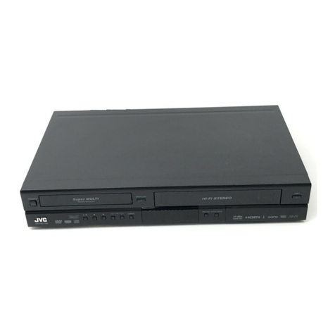
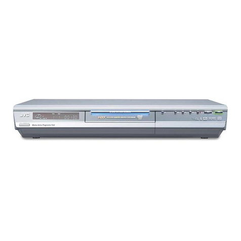
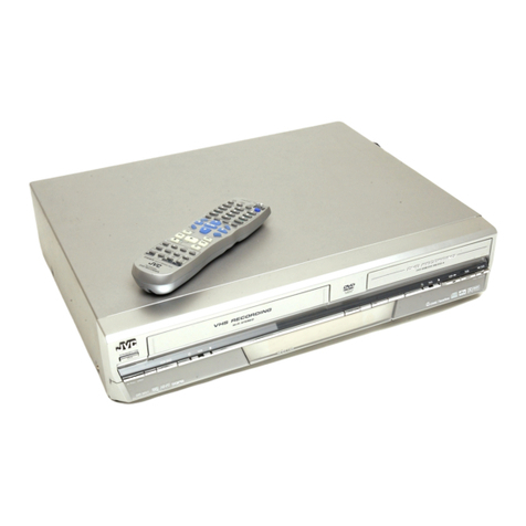
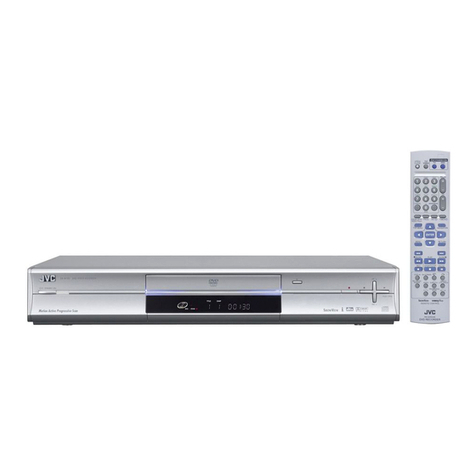
JVC DR-MV1BEU2 User manual

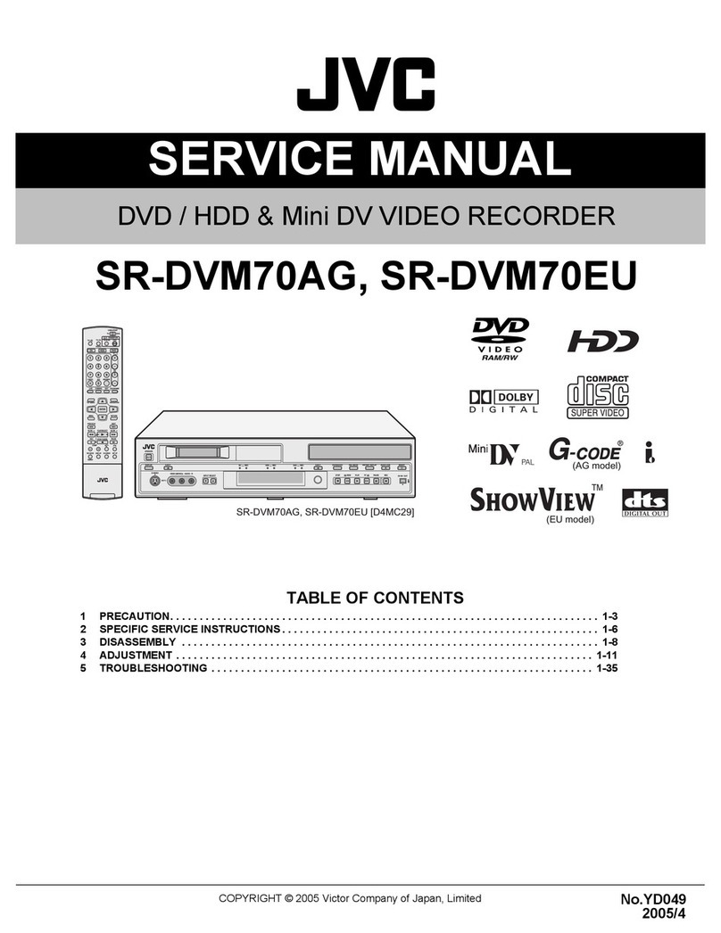
SERVICE MANUAL
COPYRIGHT © 2005 Victor Company of Japan, Limited No.YD014B
2005/7
DVD VIDEO RECORDER & VIDEO CASSETTE RECORDER
YD014B20057
DR-MV1BEU2, DR-MV1SEK2,
DR-MV1SEU2
TABLE OF CONTENTS
1 PRECAUTION. . . . . . . . . . . . . . . . . . . . . . . . . . . . . . . . . . . . . . . . . . . . . . . . . . . . . . . . . . . . . . . . . . . . . . . . . 1-3
2 SPECIFIC SERVICE INSTRUCTIONS . . . . . . . . . . . . . . . . . . . . . . . . . . . . . . . . . . . . . . . . . . . . . . . . . . . . . . 1-3
3 DISASSEMBLY . . . . . . . . . . . . . . . . . . . . . . . . . . . . . . . . . . . . . . . . . . . . . . . . . . . . . . . . . . . . . . . . . . . . . . . 1-3
4 ADJUSTMENT . . . . . . . . . . . . . . . . . . . . . . . . . . . . . . . . . . . . . . . . . . . . . . . . . . . . . . . . . . . . . . . . . . . . . . . . 1-3
5 TROUBLESHOOTING . . . . . . . . . . . . . . . . . . . . . . . . . . . . . . . . . . . . . . . . . . . . . . . . . . . . . . . . . . . . . . . . . . 1-3
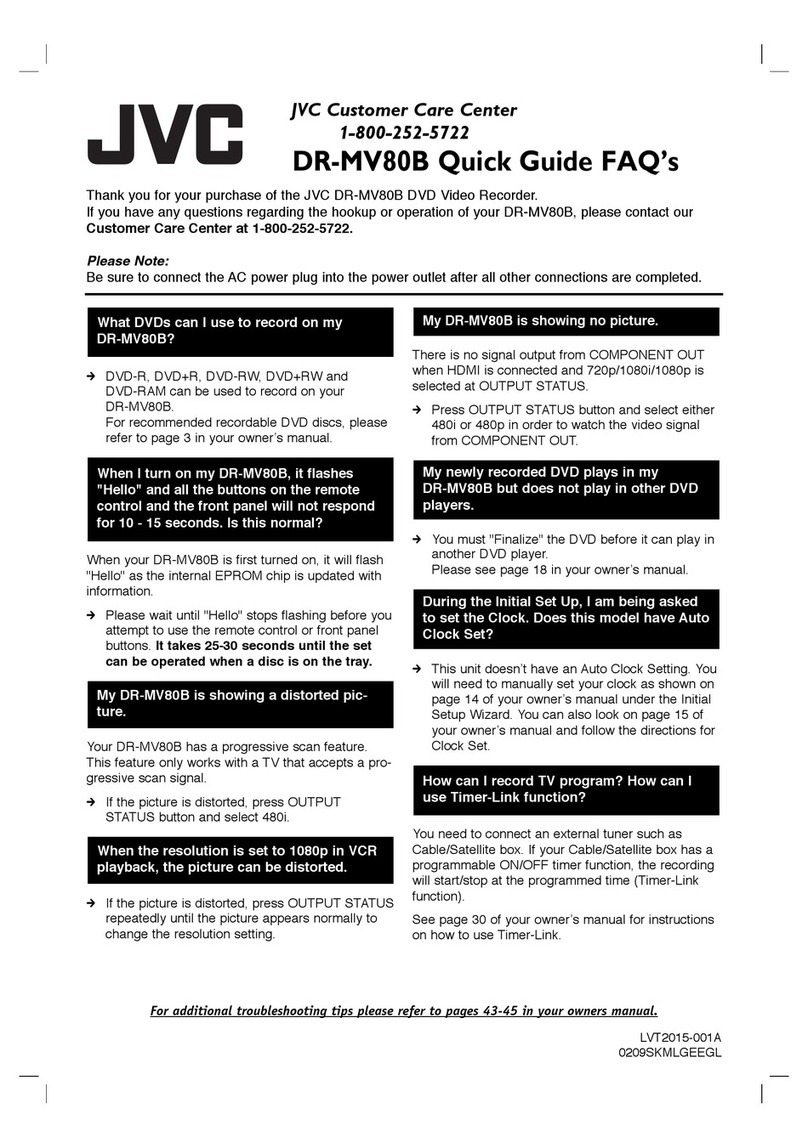
This model is a model to whom the DVD drive unit and some parts are
changed based on DR-MV1BEU, DR-MV1SEK, DR-MV1SEU.
Please see page 2 about details and the distinction method.
Since this service manual has indicated only the "Parts List",
please refer to another manual (DR-MV1BEU,
DR-MV1SEK, DR-MV1SEU ISSUE No.YD014 2004/6) about other items.
F-1
POWER
VCR EJECT
DVD
S-VIDEO VIDEO (MONO)L - AUDIO - R
VCR/DVD TIMER VCR REC OPEN/CLOSE STOP PLAY
REMAIN
REC MODE SLOW
<< >>
REC PAUSE REW FF CH DV IN
REC LINK
DVD
TIMER DVD DVDREC VCR DUBBING
PULL-OPEN PULL-OPEN
PROG/CHECK
DISPLAY ON SCREEN
DVD
TIMER VCR
/DVD
VCR
TIMER
SLOW
PREVIOUS NEXT
CLEAR
SLOW
PAU S ESTOP/
PLAY/SELECT
REMAIN REC
CH
AUDIO
SUBTITLE
ANGLE
TV/VCR
REC MODE
LIVE CHECK
DVDTV
CABLE/DBS
ABC DEF
JKL MNO
TUV
GHI
PQRS WXYZ
NUMBER / TV CH / DVD CHNUMBER / TV CH / DVD CH
MEMO/MARK
PROGRESSIVE
SCAN
VCR PLUS+
AUX
SET UP
RETURN
CANCEL
NAVIGA
TION
TOPMENU
MENU
TV
VOL.
TV/CBL /DVD
TV/DVD TV
TV
/
CBL/DBS
/DVD
1
4
7
2
5
8
0
3
6
9
ENTER
DR-MV1BEU2, DR-MV1SEK2, DR-MV1SEU2 [D3RV21]
(EK model)
(EU model)

1-2 (No.YD014B)
L-1
L-2
IN/OUT
IN/DECODER
ANTENNA
IN
OUT
DVD/VCR
AUDIO OUT
LEFT
RIGHT
DIGITAL
AUDIO OUT
PCM/
STREAM
COAXIAL OPTICAL
DVD
DVD
SAT CONTROL
COMPONENT
VIDEO OUT
PB
PR
Y
About this service manual
This model is a model to whom the DVD drive unit and some parts are changed based
on DR-MV1BEU, DR-MV1SEK, DR-MV1SEU.
Since the way of recognizing is explained below, in the case of DR-MV1BEU2, DR-MV1SEK2,
DR-MV1SEU2, please use this manual.
In the case of DR-MV1BEU, DR-MV1SEK, DR-MV1SEU, please refer to another service
manual (No.YD014 2004/6).
The surface of
a rear panel
HOW TO IDENTIFY MODELS
How to recognize from the appearance of the model concerned is written below.
Please distinguish from several contents currently printed on the rating label of the rear panel.
BLANK : DR-MV1BEU, DR-MV1SEK, DR-MV1SEU
2 : DR-MV1BEU2, DR-MV1SEK2, DR-MV1SEU2

(No.YD014B)1-3
SECTION 1
PRECAUTION
Please refer to "DR-MV1BEU, DR-MV1SEK, DR-MV1SEU (issue number : YD014)"
about this section.
SECTION 2
SPECIFIC SERVICE INSTRUCTIONS
Please refer to "DR-MV1BEU, DR-MV1SEK, DR-MV1SEU (issue number : YD014)"
about this section.
SECTION 3
DISASSEMBLY
Please refer to "DR-MV1BEU, DR-MV1SEK, DR-MV1SEU (issue number : YD014)"
about this section.
SECTION 4
ADJUSTMENT
Please refer to "DR-MV1BEU, DR-MV1SEK, DR-MV1SEU (issue number : YD014)"
about this section.
SECTION 5
TROUBLESHOOTING
Please refer to "DR-MV1BEU, DR-MV1SEK, DR-MV1SEU (issue number : YD014)"
about this section.

(No.YD014B)
AV & MULTIMEDIA COMPANY DIGITAL VIDEO STORAGE CATEGORY 12, 3-chome, Moriya-cho, kanagawa-ku, Yokohama, kanagawa-prefecture, 221-8528, Japan
Victor Company of Japan, Limited
VPT
Printed in Japan

(No.YD014B)3-1
[DR-MV1BEU2,DR-MV1SEK2,DR-MV1SEU2]
* SAFETY PRECAUTION
Parts identified by the symbol are critical for safety. Replace only with
specified part numbers.
* BEWARE OF BOGUS PARTS
Parts that do not meet specifications may cause trouble in regard to safety
and performance. We recommend that genuine JVC parts be used.
* (x_) in a description column shows the number of the used part.
- Contents -
Exploded view of general assembly and parts list ..................... 3-2
Electrical parts list ...................................................................... 3-5
PARTS LIST

3-2(No.YD014B)
Exploded view of general assembly and parts list
Block No. M1MM
j
j
j
501
501B
501A
501F
501J
501C
501E
501D
501F
501H
502
503
503
504
504
504
504
e'
e'
e'
526
526
526
543
544
mk
Jack board
assembly<36>
532
CN5001
c
c
4c
1
2
c
3
f
525
Switching regulator board
assembly<01>
525
525
529
d
e
d
e'
e
e' e
e'
e
e' e
526
Junction board assembly<92>
j
3
j
h
g
2
1
535
520
519
521
520
520
519
519
505
Main board assembly<03>
Terminal board assembly<06>
VHS machanism assembly<M2>
Video switch board assembly<83>
Digital board
assembly<02>
a
2
1
JS3001
p
CN7113 CN7114 CN7115
CN914 CN913 CN915
CN502
CN503
524
524
535
535
548
547
from FRONT PANEL
(Operation/jack WR7201)
i
i
i
f
522
541
516
517
523
527
527 527
eb
d
e
m
dkeb
e
ab
i
e
ba
i
c
c
c
i
511
533
533
533
533
j
a
a
gh
a
c
n
n
513
513 512
3
n
n
p
q
r
s
524
536
536
Tuner board assembly<24> 515
b
b
b
b
518
515
518
518 518
515
514
509
545
542
515
508
DR-MV1BEU2
DR-MV1SEK2
A
B
DR-MV1SEU2
C
MODEL
MARK
MODEL
MARK

(No.YD014B)3-3
Main board assembly
CN7111
BRACKET(CENTER)
<HOW TO REMOVE>
NOTE) Replace the attached FITING.
by doing the slide.
Take it out up
It pulls out toward
front side.
FITTING(DVD) ASSY
TRAY
CN5302
CN7107
DRIVE
CN7112
CN3102
A/C HEAD
CN3103
CN7102
CN2601
CN8001
CN2001
CN5311
CN7111
CN5301
CN7104
Digital board assembly
CN7103
UNIT
CN2201
CN1404
CN7105
Junction board
assembly
CN5304
CN5501
Swtching
regurator
board assembly
FAN
CN5001
CN7118
CN7117
CN7116
CN6001
CN6002
CN6003
CN501
CN7119
CN504
CN4302 CN301
C
B
from FRONT PANEL
(Operation/jack CN7201)
CN7002
NOTE) INSERT FFC WIRE TO THE CONNECTOR BEFORE ATTACHING TO FRONT PANEL.
CN7201
CN3104
TOP SIDE
NOTE)Push the slack of the wire
NOTE)Pass slit PCB through wire.
CN7201
CN7002
to Main board aseembly
(CN7112)
Operation/jack board assembly<27>
into the FW7001 side.
FW7001
CN7001
BOTTOM SIDE
NOTE) FJ CONN should be
insert as follows.
Switch/display board assembly<28>
CN
NG
CN
DRAWING FROM DIRECTION B
OK
when it is inserted to the DRIVE UNIT.
DRAWING FROM DIRECTION C
NOTE) Push both ends of connector
506
506
506
506
507
507
507
WR3
507
506
WR5
WR4
538
WR9
WR10
WR2
WR6 WR8
WR7
WR1
WR11
Demod board assembly<14>
Junction board assembly CN7102 Main board assembly CN3103
Junction board assembly CN8001 Main board assembly CN2601
Junction board assembly CN5501 Switching regulator board assembly CN5304
Main board assembly CN5311 Switching regulator board assembly CN5301
DR-MV1BEU2
DR-MV1SEK2
A
B
DR-MV1SEU2
C
MODEL
MARK
MODEL
MARK

3-4(No.YD014B)
General assembly
Block No. [M][1][M][M]
Symbol No. Part No. Part Name Description Local
501 LP10526-013B FRONT PANEL ASSY A
501 LP10526-008C FRONT PANEL ASSY B
501 LP10526-007C FRONT PANEL ASSY C
501A LP21232-006A CASSETTE DOOR A
501A LP21232-001A CASSETTE DOOR B,C
501B PQ46448 TORSION SPRING
501C LP31358-007A DISPLAY WINDOW A
501C LP31358-005A DISPLAY WINDOW B,C
501D LP31353-003B DOOR(L) A
501D LP31353-001B DOOR(L) B,C
501E LP31354-003B DOOR(R) A
501E LP31354-001B DOOR(R) B,C
501F PU60109 CATCHER (x2)
501H LP31356-013A WINDOW(L) A
501H LP31356-008A WINDOW(L) B
501H LP31356-007A WINDOW(L) C
501J LP31357-011A WINDOW(R) A
501J LP31357-007A WINDOW(R) B
501J LP31357-006A WINDOW(R) C
502 LP10460-008B TOP COVER A
502 LP10460-004C TOP COVER B,C
503 QYSBSG3006MA TAP SCREW M3 x 6mm TOP SIDE(x2) A
503 QYSBSG3006NA TAP SCREW M3 x 6mm TOP SIDE(x2) B,C
504 QYSBSG3006MA TAP SCREW M3 x 6mm TOP REAR(x4) A
504 QYSBSG3006NA TAP SCREW M3 x 6mm TOP REAR(x4) B,C
505 PDV2625A DRUM FINAL ASSY
506 QYTDSF2608ZA TAP SCREW M2.6 x 8mm SWITCH/DISPLAY(x5)
507 QYTDSF2608ZA TAP SCREW M2.6 x 8mm OPERATION/JACK(x4)
508 LP21348-001B FITTING(DVD)
509 QAL0704-001 DRIVE UNIT
511 LP10525-001E BOTTOM CHASSIS
512 LP21222-001B BRACKET(CENTER)
513 LP31391-001A SPECIAL SCREW BRACKET(CENTER)(x2)
514 LP21223-001A BRACKET(DRIVE UNIT)
515 LP31391-001A SPECIAL SCREW BRACKET(DVD)(x4)
516 LP21134-014B REAR COVER
517 QYSBSG3006NA TAP SCREW M3 x 6mm REAR COVER(x2)
518 QYTDST3006ZA TAP SCREW M3 x 6mm DRIVE(x4)
519 QYSPSPD3008ZA SCREW M3 x 8mm DRUM(x3)
520 LP31391-002A SPECIAL SCREW MECHANISM(x3)
521 LP31391-001A SPECIAL SCREW HOUSING
522 QAR0349-001 FAN MOTOR
523 QYTDSF3008MA TAP SCREW M3 x 8mm FAN(x2)
524 LP31391-001A SPECIAL SCREW MAIN(x3)
525 LP31391-001A SPECIAL SCREW SWITCHING REGULATOR(x4)
526 LP31391-001A SPECIAL SCREW JUNCTION(x5)
527 QYTDSF3008MA TAP SCREW M3 x 8mm JACK COVER(x8)
529 QMP51K0-170-K POWER CORD 1.7m BLACK B
529 QMPK340-170-JC POWER CORD 1.7m BLACK A,C
532 LP31391-001A SPECIAL SCREW JACK
533 LP31348-001A FOOT (x4)
535 LP41140-001A INSULATOR (x3)
536 LP31391-001A SPECIAL SCREW TUNER BRACKET(x2)
538 QGZ0021A1-40 CONNECTOR (1-40)
541 QYTDST3005MA TAP SCREW M3 x 5mm TUNER
542 LP30002-0F6A SPACER VDR BRACKET
543 LP41171-001A SHIELD TIGHT
544 LP41171-001A SHIELD TIGHT
545 LP41171-001A SHIELD TIGHT
547 LP31345-001A EARTH PLATE
548 LP31345-001A EARTH PLATE
WR 1 QUQ112-0918CG-E FFC WIRE JUNCTION CN7107-MAIN CN7111
WR 2 QUQ212-0430CG-E FFC WIRE VIDEO SWITCH CN501-JUNCTION CN7104
WR 3 QUQ112-1308CG-E FFC WIRE OPERATION/JACK CN7201-MAIN CN7112
WR 4 WJT0151-001A-E E-CARD WIRE SWITCH/DISPLAY CN7001-MAIN CN3102
WR 5 QUQ212-0410CG-E FFC WIRE SWITCH/DISPLAY CN7002-JUNCTION CN7103
WR 6 QUQ105-4020AF-E FFC WIRE DRIVE UNIT-DIGITAL CN2201
WR 7 QJJ032-040804-E SIN CR C-C WIRE DRIVE UNIT-SWITCHING REGULATOR CN5303
WR 8 QUQ210-0406CC-E FFC WIRE JUNCTION CN7105-DIGITAL CN1404
WR 9 QUQ112-1420CG-E FFC WIRE TUNER CN6001-MAIN CN7116
WR10 QUQ112-1315CG-E FFC WIRE TUNER CN6002-MAIN CN7117
WR11 QUQ112-0716CG-E FFC WIRE TUNER CN6003-MAIN CN7118
DR-MV1BEU2
DR-MV1SEK2
A
B
DR-MV1SEU2
C
MODEL
MARK
MODEL
MARK

(No.YD014B)3-5
Electrical parts list
Digital board
Block No. [0][2]
Symbol No.
Part No. Part Name Description Local
PW1 LPA10236-24B DIGITAL BOARD ASSY
IC1001 JCP8059-2 IC
IC1002
HY57V161610ET-8
IC
IC1002 or
K4S161622H-UC60
IC
IC1002 or
HY57V161610ETP7
IC
IC1201 LPN0889-001E IC(FLASH) (SERVICE)
IC1202
SN74LVC373APW-X
IC(DIGITAL)
IC1203
SN74LVC373APW-X
IC(DIGITAL)
IC1401 DMN8652-B0L IC(DIGITAL)
IC1404
SN74HCT08APW-X
IC
IC1405 SN74LV08APW-X IC
IC1601
HY5DU561622DT-J
IC
IC1601 or
HY5DU561622DT-J
IC
IC1602
HY5DU561622DT-J
IC
IC1602 or
HY5DU561622DT-J
IC
IC1701
PQ015YZ01Z-X
IC
IC1801 TSB41AB2PAP IC
Q1002 2SA1037AK/QR/-X TRANSISTOR
Q1002 or 2SA1530A/QR/-X TRANSISTOR
Q1002 or 2SB709A/QR/-X TRANSISTOR
Q1003 2SA1037AK/QR/-X TRANSISTOR
Q1003 or 2SA1530A/QR/-X TRANSISTOR
Q1003 or 2SB709A/QR/-X TRANSISTOR
Q1004 2SA1037AK/QR/-X TRANSISTOR
Q1004 or 2SA1530A/QR/-X TRANSISTOR
Q1004 or 2SB709A/QR/-X TRANSISTOR
Q1005 2SA1037AK/QR/-X TRANSISTOR
Q1005 or 2SA1530A/QR/-X TRANSISTOR
Q1005 or 2SB709A/QR/-X TRANSISTOR
Q1006 2SA1037AK/QR/-X TRANSISTOR
Q1006 or 2SA1530A/QR/-X TRANSISTOR
Q1006 or 2SB709A/QR/-X TRANSISTOR
Q1007 2SA1037AK/QR/-X TRANSISTOR
Q1007 or 2SA1530A/QR/-X TRANSISTOR
Q1007 or 2SB709A/QR/-X TRANSISTOR
Q1008 UMZ1N-W
PAIR TRANSISTOR
Q1008 or BC847PN-X
PAIR TRANSISTOR
Q1008 or BC846PN-X
PAIR TRANSISTOR
Q1009
2SC2412K/QRS/-X
TRANSISTOR
Q1009 or
2SC3928A/QRS/-X
TRANSISTOR
Q1009 or 2SD601A/QRS/-X TRANSISTOR
Q1010
2SC2412K/QRS/-X
TRANSISTOR
Q1010 or
2SC3928A/QRS/-X
TRANSISTOR
Q1010 or 2SD601A/QRS/-X TRANSISTOR
Q1011
2SC2412K/QRS/-X
TRANSISTOR
Q1011 or
2SC3928A/QRS/-X
TRANSISTOR
Q1011 or 2SD601A/QRS/-X TRANSISTOR
D1001 1SS355-X SI DIODE
D1001 or MA111-X SI DIODE
D1002 1SS355-X SI DIODE
D1002 or MA111-X SI DIODE
D1401 1SS355-X SI DIODE
D1401 or MA111-X SI DIODE
D1402 1SS355-X SI DIODE
D1402 or MA111-X SI DIODE
D1403 1SS355-X SI DIODE
D1403 or MA111-X SI DIODE
C1001 NBE20JM-226X
TA E CAPACITOR
22uF 6.3V M
C1002 NBE20JM-106X
TA E CAPACITOR
10uF 6.3V M
C1003 NCB31CK-104X C CAPACITOR 0.1uF 16V K
C1004 NCB31CK-104X C CAPACITOR 0.1uF 16V K
C1005 NCB31CK-104X C CAPACITOR 0.1uF 16V K
C1007 NCB31CK-104X C CAPACITOR 0.1uF 16V K
C1008 NCB31CK-104X C CAPACITOR 0.1uF 16V K
C1009 NCB31CK-104X C CAPACITOR 0.1uF 16V K
C1012 NCB31CK-104X C CAPACITOR 0.1uF 16V K
C1014 NCB31CK-104X C CAPACITOR 0.1uF 16V K
C1015 NCB31CK-104X C CAPACITOR 0.1uF 16V K
C1017 NCB31CK-104X C CAPACITOR 0.1uF 16V K
C1018 NCB31CK-104X C CAPACITOR 0.1uF 16V K
C1019 NCB31EK-103X C CAPACITOR 0.01uF 25V K
C1020 NCB31CK-104X C CAPACITOR 0.1uF 16V K
C1026 NCB31CK-104X C CAPACITOR 0.1uF 16V K
C1030 NCB31CK-104X C CAPACITOR 0.1uF 16V K
C1032 NCB31CK-104X C CAPACITOR 0.1uF 16V K
C1033 NCB31CK-104X C CAPACITOR 0.1uF 16V K
C1034 NCB31CK-104X C CAPACITOR 0.1uF 16V K
C1035 NCB31CK-104X C CAPACITOR 0.1uF 16V K
C1036 NCB31CK-104X C CAPACITOR 0.1uF 16V K
C1038 NCB31CK-104X C CAPACITOR 0.1uF 16V K
C1039 NCB31CK-104X C CAPACITOR 0.1uF 16V K
C1041 NBE20JM-106X
TA E CAPACITOR
10uF 6.3V M
C1042 NCB31CK-104X C CAPACITOR 0.1uF 16V K
C1043 NCB31CK-104X C CAPACITOR 0.1uF 16V K
C1044 NCB31CK-104X C CAPACITOR 0.1uF 16V K
C1045 NCB31CK-104X C CAPACITOR 0.1uF 16V K
C1046 NCB31CK-104X C CAPACITOR 0.1uF 16V K
C1047 NCB31CK-104X C CAPACITOR 0.1uF 16V K
C1051 NBE20JM-106X
TA E CAPACITOR
10uF 6.3V M
C1052 NCB31CK-104X C CAPACITOR 0.1uF 16V K
C1053 NCB31EK-103X C CAPACITOR 0.01uF 25V K
C1054 NCB31CK-104X C CAPACITOR 0.1uF 16V K
C1055 NCB31CK-104X C CAPACITOR 0.1uF 16V K
C1056 NCB31CK-104X C CAPACITOR 0.1uF 16V K
C1057 NCB31CK-104X C CAPACITOR 0.1uF 16V K
C1059 NCB31CK-104X C CAPACITOR 0.1uF 16V K
C1060 NCB31CK-104X C CAPACITOR 0.1uF 16V K
C1061 NCB31CK-104X C CAPACITOR 0.1uF 16V K
C1062 NCB31EK-103X C CAPACITOR 0.01uF 25V K
C1065 NCB20JM-475X C CAPACITOR 4.7uF 6.3V M
C1077 NCB31CK-104X C CAPACITOR 0.1uF 16V K
C1089 NCB31CK-104X C CAPACITOR 0.1uF 16V K
C1090 NCB31CK-104X C CAPACITOR 0.1uF 16V K
C1091 NCB31CK-104X C CAPACITOR 0.1uF 16V K
C1092 NCB31CK-104X C CAPACITOR 0.1uF 16V K
C1093 NCB31CK-104X C CAPACITOR 0.1uF 16V K
C1094 NCB31CK-104X C CAPACITOR 0.1uF 16V K
C1095 NBE20JM-106X
TA E CAPACITOR
10uF 6.3V M
C1096 NCB31CK-104X C CAPACITOR 0.1uF 16V K
C1097 NCB31CK-104X C CAPACITOR 0.1uF 16V K
C1098 NCB31CK-104X C CAPACITOR 0.1uF 16V K
C1203 NCB31CK-104X C CAPACITOR 0.1uF 16V K
C1204 NEHM0JM-476X E CAPACITOR 47uF 6.3V M
C1206 NCB31CK-104X C CAPACITOR 0.1uF 16V K
C1207 NCB31CK-104X C CAPACITOR 0.1uF 16V K
C1401 NCB31CK-104X C CAPACITOR 0.1uF 16V K
C1402 NCB31CK-104X C CAPACITOR 0.1uF 16V K
C1403 NCB31CK-104X C CAPACITOR 0.1uF 16V K
C1404 NEHM0JM-107X E CAPACITOR 100uF 6.3V M
C1405 NCB31CK-104X C CAPACITOR 0.1uF 16V K
C1406 NCB31CK-104X C CAPACITOR 0.1uF 16V K
C1407 NCB31CK-104X C CAPACITOR 0.1uF 16V K
C1408 NCB31CK-104X C CAPACITOR 0.1uF 16V K
C1409 NCB31CK-104X C CAPACITOR 0.1uF 16V K
C1410 NCB31CK-104X C CAPACITOR 0.1uF 16V K
C1411 NEHM0JM-107X E CAPACITOR 100uF 6.3V M
C1412 NCB31CK-104X C CAPACITOR 0.1uF 16V K
C1413 NEHM0JM-107X E CAPACITOR 100uF 6.3V M
C1414 NCB31CK-104X C CAPACITOR 0.1uF 16V K
C1416 NCB31CK-104X C CAPACITOR 0.1uF 16V K
C1417 NCB31CK-104X C CAPACITOR 0.1uF 16V K
C1418 NCB31CK-104X C CAPACITOR 0.1uF 16V K
C1420 NBE20JM-106X
TA E CAPACITOR
10uF 6.3V M
C1421 NCB31CK-104X C CAPACITOR 0.1uF 16V K
C1422 NCB31CK-104X C CAPACITOR 0.1uF 16V K
C1423 NCB31CK-104X C CAPACITOR 0.1uF 16V K
C1424 NCB31CK-104X C CAPACITOR 0.1uF 16V K
C1425 NCB31CK-104X C CAPACITOR 0.1uF 16V K
C1426 NCB31CK-104X C CAPACITOR 0.1uF 16V K
C1427 NBE20JM-106X
TA E CAPACITOR
10uF 6.3V M
C1428 NCB31CK-104X C CAPACITOR 0.1uF 16V K
C1429 NCB31CK-104X C CAPACITOR 0.1uF 16V K
C1430 NCB31CK-104X C CAPACITOR 0.1uF 16V K
C1431 NCB31CK-104X C CAPACITOR 0.1uF 16V K
Symbol No.
Part No. Part Name Description Local
DR-MV1BEU2
DR-MV1SEK2
A
B
DR-MV1SEU2
C
MODEL
MARK
MODEL
MARK
3-6(No.YD014B)
C1432 NCB31CK-104X C CAPACITOR 0.1uF 16V K
C1433 NCB31CK-104X C CAPACITOR 0.1uF 16V K
C1435 NBE20JM-106X
TA E CAPACITOR
10uF 6.3V M
C1436 NCB31CK-104X C CAPACITOR 0.1uF 16V K
C1437 NCB31CK-104X C CAPACITOR 0.1uF 16V K
C1438 NCB31CK-104X C CAPACITOR 0.1uF 16V K
C1439 NCB31CK-104X C CAPACITOR 0.1uF 16V K
C1440 NCB31CK-104X C CAPACITOR 0.1uF 16V K
C1441 NCB31CK-104X C CAPACITOR 0.1uF 16V K
C1442 NCB31CK-104X C CAPACITOR 0.1uF 16V K
C1443 NCB31CK-104X C CAPACITOR 0.1uF 16V K
C1444 NCB31CK-104X C CAPACITOR 0.1uF 16V K
C1445 NCB31CK-104X C CAPACITOR 0.1uF 16V K
C1446 NCB31CK-104X C CAPACITOR 0.1uF 16V K
C1447 NCB31CK-104X C CAPACITOR 0.1uF 16V K
C1448 NCB31EK-103X C CAPACITOR 0.01uF 25V K
C1449 NCB31CK-104X C CAPACITOR 0.1uF 16V K
C1450 NCB31CK-104X C CAPACITOR 0.1uF 16V K
C1452 NCB31CK-104X C CAPACITOR 0.1uF 16V K
C1453 NCB31CK-104X C CAPACITOR 0.1uF 16V K
C1455 NCB31CK-104X C CAPACITOR 0.1uF 16V K
C1457 NCB31CK-104X C CAPACITOR 0.1uF 16V K
C1458 NCB31CK-104X C CAPACITOR 0.1uF 16V K
C1601 NBAD0GM-227X
OS E CAPACITOR
220uF 2.5V M
C1602 NBAD0GM-227X
OS E CAPACITOR
220uF 2.5V M
C1605 NCB31CK-104X C CAPACITOR 0.1uF 16V K
C1606 NCB31CK-104X C CAPACITOR 0.1uF 16V K
C1607 NCB31CK-104X C CAPACITOR 0.1uF 16V K
C1608 NCB31CK-104X C CAPACITOR 0.1uF 16V K
C1609 NCB31CK-104X C CAPACITOR 0.1uF 16V K
C1610 NCB31CK-104X C CAPACITOR 0.1uF 16V K
C1611 NCB31CK-104X C CAPACITOR 0.1uF 16V K
C1612 NCB31CK-104X C CAPACITOR 0.1uF 16V K
C1613 NCB31CK-104X C CAPACITOR 0.1uF 16V K
C1614 NCB31CK-104X C CAPACITOR 0.1uF 16V K
C1615 NCB31CK-104X C CAPACITOR 0.1uF 16V K
C1616 NCB31CK-104X C CAPACITOR 0.1uF 16V K
C1617 NCB31CK-104X C CAPACITOR 0.1uF 16V K
C1618 NCB31CK-104X C CAPACITOR 0.1uF 16V K
C1619 NCB31CK-104X C CAPACITOR 0.1uF 16V K
C1620 NCB31CK-104X C CAPACITOR 0.1uF 16V K
C1621 NCB31CK-104X C CAPACITOR 0.1uF 16V K
C1622 NCB31CK-104X C CAPACITOR 0.1uF 16V K
C1623 NCB31CK-104X C CAPACITOR 0.1uF 16V K
C1624 NCB31CK-104X C CAPACITOR 0.1uF 16V K
C1625 NCB31CK-104X C CAPACITOR 0.1uF 16V K
C1638 NCB31CK-104X C CAPACITOR 0.1uF 16V K
C1640 NCB31CK-104X C CAPACITOR 0.1uF 16V K
C1642 NCB31CK-104X C CAPACITOR 0.1uF 16V K
C1644 NCB31CK-104X C CAPACITOR 0.1uF 16V K
C1646 NCB31CK-104X C CAPACITOR 0.1uF 16V K
C1648 NCB31CK-104X C CAPACITOR 0.1uF 16V K
C1650 NCB31CK-104X C CAPACITOR 0.1uF 16V K
C1652 NCB31CK-104X C CAPACITOR 0.1uF 16V K
C1654 NCB31CK-104X C CAPACITOR 0.1uF 16V K
C1656 NCB31CK-104X C CAPACITOR 0.1uF 16V K
C1658 NCB31CK-104X C CAPACITOR 0.1uF 16V K
C1701 NCB31CK-104X C CAPACITOR 0.1uF 16V K
C1702 NEHM0JM-107X E CAPACITOR 100uF 6.3V M
C1703 NCB31CK-104X C CAPACITOR 0.1uF 16V K
C1704 NEHM0JM-107X E CAPACITOR 100uF 6.3V M
C1706 NCB31CK-104X C CAPACITOR 0.1uF 16V K
C1707 NCB31CK-104X C CAPACITOR 0.1uF 16V K
C1708 NBE40JM-476X
TA E CAPACITOR
47uF 6.3V M
C1710 NBE40JM-476X
TA E CAPACITOR
47uF 6.3V M
C1801 NCB30JK-105X C CAPACITOR 1uF 6.3V K
C1802 NDC31HJ-271X C CAPACITOR 270pF 50V J
C1803 NBE20JM-106X
TA E CAPACITOR
10uF 6.3V M
C1804 NCB31CK-104X C CAPACITOR 0.1uF 16V K
C1805 NCB31CK-104X C CAPACITOR 0.1uF 16V K
C1806 NBE20JM-106X
TA E CAPACITOR
10uF 6.3V M
C1807 NCB31CK-104X C CAPACITOR 0.1uF 16V K
C1808 NDC31HJ-120X C CAPACITOR 12pF 50V J
C1809 NDC31HJ-120X C CAPACITOR 12pF 50V J
C1811 NCB31CK-104X C CAPACITOR 0.1uF 16V K
C1812 NCB31CK-104X C CAPACITOR 0.1uF 16V K
C2201 NCB31CK-104X C CAPACITOR 0.1uF 16V K
C2202 NCB31CK-104X C CAPACITOR 0.1uF 16V K
Symbol No.
Part No. Part Name Description Local
R1001 NRSA63D-221X MG RESISTOR 220
Ω
1/16W D
R1002 NRSA63J-0R0X MG RESISTOR 0
Ω
1/16W J
R1003 NRSA63J-0R0X MG RESISTOR 0
Ω
1/16W J
R1004 NRSA63J-0R0X MG RESISTOR 0
Ω
1/16W J
R1005 NRSA63J-103X MG RESISTOR 10k
Ω
1/16W J
R1006 NRSA63J-0R0X MG RESISTOR 0
Ω
1/16W J
R1007 NRSA63J-103X MG RESISTOR 10k
Ω
1/16W J
R1009 NRSA63J-103X MG RESISTOR 10k
Ω
1/16W J
R1012 NRSA63J-0R0X MG RESISTOR 0
Ω
1/16W J
R1013 NRSA02J-0R0X MG RESISTOR 0
Ω
1/10W J
R1014 NRSA02J-0R0X MG RESISTOR 0
Ω
1/10W J
R1015 NRSA02J-0R0X MG RESISTOR 0
Ω
1/10W J
R1017 NRSA63J-0R0X MG RESISTOR 0
Ω
1/16W J
R1018 NRSA63J-0R0X MG RESISTOR 0
Ω
1/16W J
R1019 NRSA63J-0R0X MG RESISTOR 0
Ω
1/16W J
R1021 NRSA63D-332X MG RESISTOR 3.3k
Ω
1/16W D
R1022 NRSA63D-152X MG RESISTOR 1.5k
Ω
1/16W D
R1024 NRSA63D-272X MG RESISTOR 2.7k
Ω
1/16W D
R1027 NRSA63J-272X MG RESISTOR 2.7k
Ω
1/16W J
R1028 NRSA63J-272X MG RESISTOR 2.7k
Ω
1/16W J
R1029 NRSA63J-0R0X MG RESISTOR 0
Ω
1/16W J
R1030 NRSA63J-103X MG RESISTOR 10k
Ω
1/16W J
R1031 NRSA63J-103X MG RESISTOR 10k
Ω
1/16W J
R1032 NRSA63J-103X MG RESISTOR 10k
Ω
1/16W J
R1033 NRSA63J-471X MG RESISTOR 470
Ω
1/16W J
R1035 NQR0129-002X FERRITE BEADS
R1036 NRSA63J-102X MG RESISTOR 1k
Ω
1/16W J
R1037 NRSA63D-101X MG RESISTOR 100
Ω
1/16W D
R1038 NQR0129-002X FERRITE BEADS
R1039 NRSA63J-102X MG RESISTOR 1k
Ω
1/16W J
R1040 NRSA63D-101X MG RESISTOR 100
Ω
1/16W D
R1041 NQR0129-002X FERRITE BEADS
R1042 NRSA63J-102X MG RESISTOR 1k
Ω
1/16W J
R1043 NRSA63D-151X MG RESISTOR 150
Ω
1/16W D
R1044 NQR0129-002X FERRITE BEADS
R1045 NRSA63J-102X MG RESISTOR 1k
Ω
1/16W J
R1046 NRSA63J-332X MG RESISTOR 3.3k
Ω
1/16W J
R1047 NRSA63D-201X MG RESISTOR 200
Ω
1/16W D
R1048 NRSA63J-0R0X MG RESISTOR 0
Ω
1/16W J
R1049 NRSA63J-102X MG RESISTOR 1k
Ω
1/16W J
R1050 NRSA63J-152X MG RESISTOR 1.5k
Ω
1/16W J
R1051 NRSA63D-271X MG RESISTOR 270
Ω
1/16W D
R1052 NRSA63J-0R0X MG RESISTOR 0
Ω
1/16W J
R1053 NRSA63J-102X MG RESISTOR 1k
Ω
1/16W J
R1054 NRSA63D-332X MG RESISTOR 3.3k
Ω
1/16W D
R1055 NRSA63D-181X MG RESISTOR 180
Ω
1/16W D
R1056 NRSA63J-222X MG RESISTOR 2.2k
Ω
1/16W J
R1057 NRSA63J-330X MG RESISTOR 33
Ω
1/16W J
R1059 NRSA63J-471X MG RESISTOR 470
Ω
1/16W J
R1060 NRSA63J-223X MG RESISTOR 22k
Ω
1/16W J
R1061 NRSA63J-223X MG RESISTOR 22k
Ω
1/16W J
R1065 NRSA63J-121X MG RESISTOR 120
Ω
1/16W J
R1066 NRSA63J-101X MG RESISTOR 100
Ω
1/16W J
R1067 NRSA63J-121X MG RESISTOR 120
Ω
1/16W J
R1068 NRSA63D-222X MG RESISTOR 2.2k
Ω
1/16W D
R1069 NRSA63D-222X MG RESISTOR 2.2k
Ω
1/16W D
R1070 NRSA63D-122X MG RESISTOR 1.2k
Ω
1/16W D
R1071 NRSA63D-152X MG RESISTOR 1.5k
Ω
1/16W D
R1072 NRSA63J-0R0X MG RESISTOR 0
Ω
1/16W J
R1216 NRSA63J-101X MG RESISTOR 100
Ω
1/16W J
R1217 NRSA63J-101X MG RESISTOR 100
Ω
1/16W J
R1218 NRSA63J-101X MG RESISTOR 100
Ω
1/16W J
R1219 NRSA63J-101X MG RESISTOR 100
Ω
1/16W J
R1220 NRSA63J-101X MG RESISTOR 100
Ω
1/16W J
R1221 NRSA63J-101X MG RESISTOR 100
Ω
1/16W J
R1222 NRSA63J-0R0X MG RESISTOR 0
Ω
1/16W J
R1223 NRSA63J-472X MG RESISTOR 4.7k
Ω
1/16W J
R1224 NRSA63J-472X MG RESISTOR 4.7k
Ω
1/16W J
R1225 NRSA63J-103X MG RESISTOR 10k
Ω
1/16W J
R1226 NRSA63J-472X MG RESISTOR 4.7k
Ω
1/16W J
R1229 NRSA63J-472X MG RESISTOR 4.7k
Ω
1/16W J
R1230 NRSA63J-472X MG RESISTOR 4.7k
Ω
1/16W J
R1231 NRSA63J-472X MG RESISTOR 4.7k
Ω
1/16W J
R1401 NRSA63F-1181X MG RESISTOR 1.18k
Ω
1/16W F
R1402 NRSA63J-0R0X MG RESISTOR 0
Ω
1/16W J
R1408 NRSA63J-102X MG RESISTOR 1k
Ω
1/16W J
R1409 NRSA63J-103X MG RESISTOR 10k
Ω
1/16W J
Symbol No.
Part No. Part Name Description Local
DR-MV1BEU2
DR-MV1SEK2
A
B
DR-MV1SEU2
C
MODEL
MARK
MODEL
MARK
(No.YD014B)3-7
R1410 NRSA63J-103X MG RESISTOR 10k
Ω
1/16W J
R1411 NRSA63J-101X MG RESISTOR 100
Ω
1/16W J
R1412 NRSA63J-103X MG RESISTOR 10k
Ω
1/16W J
R1413 NRSA63J-103X MG RESISTOR 10k
Ω
1/16W J
R1414 NRSA63J-102X MG RESISTOR 1k
Ω
1/16W J
R1415 NRSA63J-102X MG RESISTOR 1k
Ω
1/16W J
R1416 NRSA63J-102X MG RESISTOR 1k
Ω
1/16W J
R1417 NRSA63J-102X MG RESISTOR 1k
Ω
1/16W J
R1419 NRSA63J-101X MG RESISTOR 100
Ω
1/16W J
R1420 NRSA63J-101X MG RESISTOR 100
Ω
1/16W J
R1427 NRSA63J-101X MG RESISTOR 100
Ω
1/16W J
R1428 NRSA63J-101X MG RESISTOR 100
Ω
1/16W J
R1429 NRSA63J-101X MG RESISTOR 100
Ω
1/16W J
R1430 NRSA63J-101X MG RESISTOR 100
Ω
1/16W J
R1431 NRSA63J-101X MG RESISTOR 100
Ω
1/16W J
R1434 NRSA63J-101X MG RESISTOR 100
Ω
1/16W J
R1435 NRSA63J-101X MG RESISTOR 100
Ω
1/16W J
R1436 NRSA63J-101X MG RESISTOR 100
Ω
1/16W J
R1437 NRSA63J-0R0X MG RESISTOR 0
Ω
1/16W J
R1438 NRSA63J-101X MG RESISTOR 100
Ω
1/16W J
R1439 NRSA63J-101X MG RESISTOR 100
Ω
1/16W J
R1440 NRSA63J-101X MG RESISTOR 100
Ω
1/16W J
R1441 NRSA63J-103X MG RESISTOR 10k
Ω
1/16W J
R1443 NRSA63J-472X MG RESISTOR 4.7k
Ω
1/16W J
R1444 NRSA63J-472X MG RESISTOR 4.7k
Ω
1/16W J
R1445 NRSA63J-101X MG RESISTOR 100
Ω
1/16W J
R1446 NRSA63J-101X MG RESISTOR 100
Ω
1/16W J
R1447 NRSA63J-101X MG RESISTOR 100
Ω
1/16W J
R1448 NRSA63J-101X MG RESISTOR 100
Ω
1/16W J
R1449 NRSA63J-101X MG RESISTOR 100
Ω
1/16W J
R1450 NRSA63J-101X MG RESISTOR 100
Ω
1/16W J
R1451 NRSA63J-101X MG RESISTOR 100
Ω
1/16W J
R1452 NRSA63J-101X MG RESISTOR 100
Ω
1/16W J
R1458 NRSA63J-101X MG RESISTOR 100
Ω
1/16W J
R1459 NRSA63J-101X MG RESISTOR 100
Ω
1/16W J
R1460 NRSA63J-101X MG RESISTOR 100
Ω
1/16W J
R1461 NRSA63J-101X MG RESISTOR 100
Ω
1/16W J
R1462 NRSA63J-101X MG RESISTOR 100
Ω
1/16W J
R1465 NRSA63J-101X MG RESISTOR 100
Ω
1/16W J
R1466 NRSA63J-101X MG RESISTOR 100
Ω
1/16W J
R1468 NRSA63J-101X MG RESISTOR 100
Ω
1/16W J
R1469 NRSA63J-102X MG RESISTOR 1k
Ω
1/16W J
R1470 NRSA63J-102X MG RESISTOR 1k
Ω
1/16W J
R1471 NRSA63J-101X MG RESISTOR 100
Ω
1/16W J
R1472 NRSA63J-0R0X MG RESISTOR 0
Ω
1/16W J
R1473 NRSA63J-101X MG RESISTOR 100
Ω
1/16W J
R1474 NRSA63J-101X MG RESISTOR 100
Ω
1/16W J
R1475 NRSA63J-101X MG RESISTOR 100
Ω
1/16W J
R1476 NRSA63J-101X MG RESISTOR 100
Ω
1/16W J
R1477 NRSA63J-101X MG RESISTOR 100
Ω
1/16W J
R1478 NRSA63J-101X MG RESISTOR 100
Ω
1/16W J
R1479 NRSA63J-101X MG RESISTOR 100
Ω
1/16W J
R1480 NRSA63J-0R0X MG RESISTOR 0
Ω
1/16W J
R1481 NRSA63J-0R0X MG RESISTOR 0
Ω
1/16W J
R1482 NRSA63J-0R0X MG RESISTOR 0
Ω
1/16W J
R1491 NRSA63J-102X MG RESISTOR 1k
Ω
1/16W J
R1493 NRSA63J-0R0X MG RESISTOR 0
Ω
1/16W J
R1496 NRSA63J-103X MG RESISTOR 10k
Ω
1/16W J
R1497 NRSA63J-103X MG RESISTOR 10k
Ω
1/16W J
R1498 NRSA63J-103X MG RESISTOR 10k
Ω
1/16W J
R1601 NRSA63J-100X MG RESISTOR 10
Ω
1/16W J
R1602 NRSA63J-100X MG RESISTOR 10
Ω
1/16W J
R1603 NRSA63J-100X MG RESISTOR 10
Ω
1/16W J
R1604 NRSA63J-100X MG RESISTOR 10
Ω
1/16W J
R1605 NRSA63J-470X MG RESISTOR 47
Ω
1/16W J
R1606 NRSA63J-470X MG RESISTOR 47
Ω
1/16W J
R1607 NRSA63J-470X MG RESISTOR 47
Ω
1/16W J
R1608 NRSA63J-470X MG RESISTOR 47
Ω
1/16W J
R1613 NRSA63J-0R0X MG RESISTOR 0
Ω
1/16W J
R1614 NRSA63J-0R0X MG RESISTOR 0
Ω
1/16W J
R1615 NRSA63J-0R0X MG RESISTOR 0
Ω
1/16W J
R1616 NRSA63J-0R0X MG RESISTOR 0
Ω
1/16W J
R1617 NRSA63J-270X MG RESISTOR 27
Ω
1/16W J
R1618 NRSA63J-270X MG RESISTOR 27
Ω
1/16W J
R1619 NRSA63J-101X MG RESISTOR 100
Ω
1/16W J
R1620 NRSA63J-101X MG RESISTOR 100
Ω
1/16W J
R1621 NRSA63J-270X MG RESISTOR 27
Ω
1/16W J
R1622 NRSA63J-270X MG RESISTOR 27
Ω
1/16W J
Symbol No.
Part No. Part Name Description Local
R1623 NRSA63J-270X MG RESISTOR 27
Ω
1/16W J
R1624 NRSA63J-270X MG RESISTOR 27
Ω
1/16W J
R1625 NRSA63J-101X MG RESISTOR 100
Ω
1/16W J
R1626 NRSA63J-101X MG RESISTOR 100
Ω
1/16W J
R1627 NRSA63J-270X MG RESISTOR 27
Ω
1/16W J
R1628 NRSA63J-270X MG RESISTOR 27
Ω
1/16W J
R1642 NRSA63J-100X MG RESISTOR 10
Ω
1/16W J
R1644 NRSA63J-470X MG RESISTOR 47
Ω
1/16W J
R1649 NRSA63J-101X MG RESISTOR 100
Ω
1/16W J
R1650 NRSA63J-101X MG RESISTOR 100
Ω
1/16W J
R1651 NRSA63J-101X MG RESISTOR 100
Ω
1/16W J
R1652 NRSA63J-101X MG RESISTOR 100
Ω
1/16W J
R1653 NRSA63J-0R0X MG RESISTOR 0
Ω
1/16W J
R1654 NRSA63J-0R0X MG RESISTOR 0
Ω
1/16W J
R1655 NRSA63J-0R0X MG RESISTOR 0
Ω
1/16W J
R1656 NRSA63J-0R0X MG RESISTOR 0
Ω
1/16W J
R1657 NRSA63J-220X MG RESISTOR 22
Ω
1/16W J
R1658 NRSA63J-220X MG RESISTOR 22
Ω
1/16W J
R1659 NRSA63J-220X MG RESISTOR 22
Ω
1/16W J
R1660 NRSA63J-220X MG RESISTOR 22
Ω
1/16W J
R1701 NRSA63J-271X MG RESISTOR 270
Ω
1/16W J
R1702 NRSA63J-102X MG RESISTOR 1k
Ω
1/16W J
R1703 NRSA63D-222X MG RESISTOR 2.2k
Ω
1/16W D
R1704 NRSA63D-222X MG RESISTOR 2.2k
Ω
1/16W D
R1801 NRSA63J-0R0X MG RESISTOR 0
Ω
1/16W J
R1802 NRSA63J-0R0X MG RESISTOR 0
Ω
1/16W J
R1803 NRSA63J-103X MG RESISTOR 10k
Ω
1/16W J
R1804 NRSA63J-103X MG RESISTOR 10k
Ω
1/16W J
R1805 NRSA63J-0R0X MG RESISTOR 0
Ω
1/16W J
R1807 NRSA63J-103X MG RESISTOR 10k
Ω
1/16W J
R1809 NRSA63J-103X MG RESISTOR 10k
Ω
1/16W J
R1810 NRSA63J-394X MG RESISTOR 390k
Ω
1/16W J
R1812 NRSA63J-0R0X MG RESISTOR 0
Ω
1/16W J
R1813 NRSA63J-560X MG RESISTOR 56
Ω
1/16W J
R1814 NRSA63J-560X MG RESISTOR 56
Ω
1/16W J
R1815 NRSA63J-560X MG RESISTOR 56
Ω
1/16W J
R1816 NRSA63J-560X MG RESISTOR 56
Ω
1/16W J
R1817 NRSA63J-512X MG RESISTOR 5.1k
Ω
1/16W J
R1818 NRSA63D-562X MG RESISTOR 5.6k
Ω
1/16W D
R1819 NRSA63D-751X MG RESISTOR 750
Ω
1/16W D
R1820 NRSA63J-103X MG RESISTOR 10k
Ω
1/16W J
R1821 NRSA63J-102X MG RESISTOR 1k
Ω
1/16W J
R1822 NRSA63J-0R0X MG RESISTOR 0
Ω
1/16W J
R2201 NRSA63J-103X MG RESISTOR 10k
Ω
1/16W J
R2202 NRSA63J-562X MG RESISTOR 5.6k
Ω
1/16W J
R2203 NRSA63J-472X MG RESISTOR 4.7k
Ω
1/16W J
R2204 NRSA63J-330X MG RESISTOR 33
Ω
1/16W J
R2205 NRSA63J-820X MG RESISTOR 82
Ω
1/16W J
R2206 NRSA63J-220X MG RESISTOR 22
Ω
1/16W J
R2207 NRSA63J-220X MG RESISTOR 22
Ω
1/16W J
R2208 NRSA63J-820X MG RESISTOR 82
Ω
1/16W J
R2209 NRSA63J-220X MG RESISTOR 22
Ω
1/16W J
R2210 NRSA63J-820X MG RESISTOR 82
Ω
1/16W J
R2211 NRSA63J-330X MG RESISTOR 33
Ω
1/16W J
R2212 NRSA63J-330X MG RESISTOR 33
Ω
1/16W J
R2213 NRSA63J-330X MG RESISTOR 33
Ω
1/16W J
R2214 NRSA63J-330X MG RESISTOR 33
Ω
1/16W J
R2215 NRSA63J-330X MG RESISTOR 33
Ω
1/16W J
RA1001 NRZ0040-0R0X NET RESISTOR 0
Ω
1/16W J x4
RA1002 NRZ0040-0R0X NET RESISTOR 0
Ω
1/16W J x4
RA1003 NRZ0034-103W NET RESISTOR 10k
Ω
1/32W J x4
RA1004 NRZ0034-103W NET RESISTOR 10k
Ω
1/32W J x4
RA1005 NRZ0034-103W NET RESISTOR 10k
Ω
1/32W J x4
RA1006 NRZ0034-103W NET RESISTOR 10k
Ω
1/32W J x4
RA1201 NRZ0034-103W NET RESISTOR 10k
Ω
1/32W J x4
RA1202 NRZ0034-103W NET RESISTOR 10k
Ω
1/32W J x4
RA1203 NRZ0034-103W NET RESISTOR 10k
Ω
1/32W J x4
RA1204 NRZ0034-103W NET RESISTOR 10k
Ω
1/32W J x4
RA1401 NRZ0040-101X NET RESISTOR 100
Ω
1/16W J x4
RA1402 NRZ0040-101X NET RESISTOR 100
Ω
1/16W J x4
RA1403 NRZ0040-101X NET RESISTOR 100
Ω
1/16W J x4
RA1404 NRZ0040-101X NET RESISTOR 100
Ω
1/16W J x4
RA1405 NRZ0034-101W NET RESISTOR 100
Ω
1/32W J x4
RA1406 NRZ0034-101W NET RESISTOR 100
Ω
1/32W J x4
RA1407 NRZ0034-101W NET RESISTOR 100
Ω
1/32W J x4
RA1408 NRZ0034-101W NET RESISTOR 100
Ω
1/32W J x4
RA1409 NRZ0034-101W NET RESISTOR 100
Ω
1/32W J x4
RA1410 NRZ0034-101W NET RESISTOR 100
Ω
1/32W J x4
Symbol No.
Part No. Part Name Description Local
DR-MV1BEU2
DR-MV1SEK2
A
B
DR-MV1SEU2
C
MODEL
MARK
MODEL
MARK

3-8(No.YD014B)
RA1411 NRZ0034-101W NET RESISTOR 100
Ω
1/32W J x4
RA1601 NRZ0040-101X NET RESISTOR 100
Ω
1/16W J x4
RA1602 NRZ0040-101X NET RESISTOR 100
Ω
1/16W J x4
RA1603 NRZ0040-101X NET RESISTOR 100
Ω
1/16W J x4
RA1604 NRZ0040-101X NET RESISTOR 100
Ω
1/16W J x4
RA1605 NRZ0040-101X NET RESISTOR 100
Ω
1/16W J x4
RA1606 NRZ0040-101X NET RESISTOR 100
Ω
1/16W J x4
RA1607 NRZ0040-101X NET RESISTOR 100
Ω
1/16W J x4
RA1608 NRZ0040-101X NET RESISTOR 100
Ω
1/16W J x4
RA1609 NRZ0040-220X NET RESISTOR 22
Ω
1/16W J x4
RA1610 NRZ0040-220X NET RESISTOR 22
Ω
1/16W J x4
RA1611 NRZ0040-220X NET RESISTOR 22
Ω
1/16W J x4
RA1612 NRZ0040-220X NET RESISTOR 22
Ω
1/16W J x4
RA1613 NRZ0040-220X NET RESISTOR 22
Ω
1/16W J x4
RA1614 NRZ0040-220X NET RESISTOR 22
Ω
1/16W J x4
RA1615 NRZ0040-220X NET RESISTOR 22
Ω
1/16W J x4
RA1616 NRZ0040-220X NET RESISTOR 22
Ω
1/16W J x4
RA1617 NRZ0040-101X NET RESISTOR 100
Ω
1/16W J x4
RA1618 NRZ0040-101X NET RESISTOR 100
Ω
1/16W J x4
RA1619 NRZ0040-101X NET RESISTOR 100
Ω
1/16W J x4
RA1620 NRZ0040-101X NET RESISTOR 100
Ω
1/16W J x4
RA1621 NRZ0040-101X NET RESISTOR 100
Ω
1/16W J x4
RA1622 NRZ0040-101X NET RESISTOR 100
Ω
1/16W J x4
RA1623 NRZ0040-101X NET RESISTOR 100
Ω
1/16W J x4
RA1624 NRZ0040-101X NET RESISTOR 100
Ω
1/16W J x4
RA1625 NRZ0040-100X NET RESISTOR 10
Ω
1/16W J x4
RA1626 NRZ0040-100X NET RESISTOR 10
Ω
1/16W J x4
RA1627 NRZ0040-100X NET RESISTOR 10
Ω
1/16W J x4
RA1628 NRZ0040-100X NET RESISTOR 10
Ω
1/16W J x4
RA1629 NRZ0040-470X NET RESISTOR 47
Ω
1/16W J x4
RA1630 NRZ0040-470X NET RESISTOR 47
Ω
1/16W J x4
RA1631 NRZ0040-470X NET RESISTOR 47
Ω
1/16W J x4
RA1632 NRZ0040-470X NET RESISTOR 47
Ω
1/16W J x4
RA1801 NRZ0034-103W NET RESISTOR 10k
Ω
1/32W J x4
RA1802 NRZ0034-103W NET RESISTOR 10k
Ω
1/32W J x4
RA2201 NRZ0040-0R0X NET RESISTOR 0
Ω
1/16W J x4
RA2202 NRZ0040-0R0X NET RESISTOR 0
Ω
1/16W J x4
RA2203 NRZ0040-0R0X NET RESISTOR 0
Ω
1/16W J x4
RA2204 NRZ0040-0R0X NET RESISTOR 0
Ω
1/16W J x4
RA2205 NRZ0040-0R0X NET RESISTOR 0
Ω
1/16W J x4
RA2206 NRZ0040-0R0X NET RESISTOR 0
Ω
1/16W J x4
RA2207 NRZ0040-0R0X NET RESISTOR 0
Ω
1/16W J x4
RA2208 NRZ0040-330X NET RESISTOR 33
Ω
1/16W J x4
RA2209 NRZ0040-330X NET RESISTOR 33
Ω
1/16W J x4
RA2210 NRZ0040-330X NET RESISTOR 33
Ω
1/16W J x4
RA2211 NRZ0040-330X NET RESISTOR 33
Ω
1/16W J x4
L1004 NQL144K-100X P COIL 10uH K
L1801 NQL144K-100X P COIL 10uH K
T1801 NQR0444-001X CHOKE COIL
B1001 NRSA02J-0R0X MG RESISTOR 0
Ω
1/10W J
B1007 NRSA02J-0R0X MG RESISTOR 0
Ω
1/10W J
B1008 NQR0339-001X FERRITE BEADS
B1204 NRSA63J-0R0X MG RESISTOR 0
Ω
1/16W J
B1802 NRSA02J-0R0X MG RESISTOR 0
Ω
1/10W J
CN1001 QGB2027L5-28X CONNECTOR B-B (1-28)
CN1002 QGB2027L5-28X CONNECTOR B-B (1-28)
CN1404 QGF1016F2-04W CONNECTOR FFC/FPC (1-4)
CN1801 QGB2027L1-10X CONNECTOR B-B (1-10)
CN2201 QGF0539C1-40W CONNECTOR FFC/FPC (1-40)
K1001 NQR0339-001X FERRITE BEADS
K1002 NRSA63J-0R0X MG RESISTOR 0
Ω
1/16W J
K1003 NQR0129-002X FERRITE BEADS
K1004 NRSA63J-0R0X MG RESISTOR 0
Ω
1/16W J
K1005 NQR0129-002X FERRITE BEADS
K1006 NRSA63J-0R0X MG RESISTOR 0
Ω
1/16W J
K1008 NRSA63J-0R0X MG RESISTOR 0
Ω
1/16W J
K1009 NRSA63J-0R0X MG RESISTOR 0
Ω
1/16W J
K1010 NQR0129-002X FERRITE BEADS
K1011 NQR0129-002X FERRITE BEADS
K1012 NQR0129-002X FERRITE BEADS
K1013 NQR0129-002X FERRITE BEADS
K1014 NQR0129-002X FERRITE BEADS
K1015 NQR0129-002X FERRITE BEADS
K1016 NQR0129-002X FERRITE BEADS
K1017 NQR0129-002X FERRITE BEADS
K1018 NQR0129-002X FERRITE BEADS
Symbol No.
Part No. Part Name Description Local
K1019 NRSA02J-0R0X MG RESISTOR 0
Ω
1/10W J
K1020 NQR0129-002X FERRITE BEADS
K1201 NRSA63J-0R0X MG RESISTOR 0
Ω
1/16W J
K1401 NRSA02J-0R0X MG RESISTOR 0
Ω
1/10W J
K1402 NRSA02J-0R0X MG RESISTOR 0
Ω
1/10W J
K1403 NRSA02J-0R0X MG RESISTOR 0
Ω
1/10W J
K1404 NQR0339-001X FERRITE BEADS
K1406 NQR0339-001X FERRITE BEADS
K1407 NRSA02J-0R0X MG RESISTOR 0
Ω
1/10W J
K1408 NRSA02J-0R0X MG RESISTOR 0
Ω
1/10W J
K1701 NRSA02J-0R0X MG RESISTOR 0
Ω
1/10W J
K1702 NRSA02J-0R0X MG RESISTOR 0
Ω
1/10W J
K1801 NRSA02J-0R0X MG RESISTOR 0
Ω
1/10W J
K2201 NQR0129-002X FERRITE BEADS
K2202 NQR0129-002X FERRITE BEADS
K2203 NQR0129-002X FERRITE BEADS
K2204 NQR0129-002X FERRITE BEADS
K2205 NQR0129-002X FERRITE BEADS
K2206 NQR0129-002X FERRITE BEADS
K2207 NQR0129-002X FERRITE BEADS
K2208 NQR0129-002X FERRITE BEADS
K2209 NQR0129-002X FERRITE BEADS
K2210 NQR0129-002X FERRITE BEADS
K2211 NQR0129-002X FERRITE BEADS
K2212 NQR0129-002X FERRITE BEADS
K2213 NQR0129-002X FERRITE BEADS
K2214 NQR0129-002X FERRITE BEADS
K2215 NQR0129-002X FERRITE BEADS
K2216 NQR0129-002X FERRITE BEADS
K2217 NQR0129-002X FERRITE BEADS
K2218 NQR0129-002X FERRITE BEADS
K2219 NQR0129-002X FERRITE BEADS
K2220 NQR0129-002X FERRITE BEADS
K2221 NQR0129-002X FERRITE BEADS
LC1401 NQR0415-002X EMI FILTER 1uF 16V Z
LC1402 NQR0415-002X EMI FILTER 1uF 16V Z
LC1403 NQR0415-002X EMI FILTER 1uF 16V Z
OT1 LP40769-001A SPACER
SD1 LP21293-001A SHIELD FRAME(DIGITAL)
X1401 NAX0580-001X CXO 27.0000MHz
X1801 NAX0666-001X CRYSTAL 24.576000MHz
Symbol No.
Part No. Part Name Description Local
DR-MV1BEU2
DR-MV1SEK2
A
B
DR-MV1SEU2
C
MODEL
MARK
MODEL
MARK
SERVICE MANUAL
COPYRIGHT © 2004 Victor Company of Japan, Limited No.YD014
2004/6
DVD VIDEO RECORDER & VIDEO CASSETTE RECORDER
DR-MV1BEK, DR-MV1BEU,
DR-MV1SEF, DR-MV1SEK,
DR-MV1SEU
For disassembling and assembling of MECHANISM ASSEMBLY, refer to the SERVICE MANUAL No.86700(MECHANISM ASSEMBLY).
TABLE OF CONTENTS
1 PRECAUTION. . . . . . . . . . . . . . . . . . . . . . . . . . . . . . . . . . . . . . . . . . . . . . . . . . . . . . . . . . . . . . . . . . . . . . . . . 1-3
2 SPECIFIC SERVICE INSTRUCTIONS . . . . . . . . . . . . . . . . . . . . . . . . . . . . . . . . . . . . . . . . . . . . . . . . . . . . . . 1-5
3 DISASSEMBLY . . . . . . . . . . . . . . . . . . . . . . . . . . . . . . . . . . . . . . . . . . . . . . . . . . . . . . . . . . . . . . . . . . . . . . . 1-8
4 ADJUSTMENT . . . . . . . . . . . . . . . . . . . . . . . . . . . . . . . . . . . . . . . . . . . . . . . . . . . . . . . . . . . . . . . . . . . . . . . 1-12
5 TROUBLESHOOTING . . . . . . . . . . . . . . . . . . . . . . . . . . . . . . . . . . . . . . . . . . . . . . . . . . . . . . . . . . . . . . . . . 1-18
F-1
POWER
VCR EJECT
DVD
S-VIDEO VIDEO (MONO) L - AUDIO - R
VCR/DVD TIMER VCR REC OPEN/CLOSE STOP PLAY
REMAIN
REC MODE SLOW
<< >>
REC PAUSE REW FF CH DV IN
REC LINK
DVD
TIMER DVD DVDREC VCR DUBBING
PULL-OPEN PULL-OPEN
PROG/CHECK
DISPLAY ON SCREEN
DVD
TIMER VCR
/DVD
VCR
TIMER
SLOW
PREVIOUS NEXT
CLEAR
SLOW
PAUSESTOP/
PLAY/SELECT
REMAIN REC
CH
AUDIO
SUBTITLE
ANGLE
TV/VCR
REC MODE
LIVE CHECK
DVDTV
CABLE/DBS
ABC DEF
JKL MNO
TUV
GHI
PQRS WXYZ
NUMBER / TV CH / DVD CHNUMBER / TV CH / DVD CH
MEMO/MARK
PROGRESSIVE
SCAN
VCR PLUS+
AUX
SET UP
RETURN
CANCEL
NAVIGA
TION
TOP MENU
MENU
TV
VOL.
TV/CBL /DVD
TV/DVD TV
TV
/
CBL/DBS
/DVD
1
4
7
2
5
8
0
3
6
9
ENTER
DR-MV1BEK, DR-MV1BEU, DR-MV1SEF,
DR-MV1SEK, DR-MV1SEU [D3RV21]
(EK model)
(EU model)
(EF model)
(EF model)
(EK, EU model)

1-2 (No.YD014)
SPECIFICATION
• Specifications shown are for SP mode unless otherwise specified.
• E.& O.E. Design and specifications subject to change without notice.
• Manufactured under license from Dolby Laboratories. "Dolby" and the double-D symbol are trademarks of Dolby Laboratories.
• "DTS" and "DTS Digital Out" are trademarks of Digital Theater Systems, Inc.
• SHOWVIEW is a trademark of Gemstar Development Corporation. The SHOWVIEW system is manufactured under licence from Gemstar Devel-
opment Corporation.(EU/EF MODEL).
• VIDEO Plus+ and PlusCode are registered trademarks of Gemstar Development Corporation. The VIDEO Plus+ system is manufactured under
license from Gemstar Development Corporation.(EK MODEL).
•(i.Link) refers to the IEEE1394-1995 industry specification and extensions thereof. The logo is used for products compliant with the i.Link stan-
dard.
DR-MV1BEK, DR-MV1SEK DR-MV1BEU, DR-MV1SEU DR-MV1SEF
GENERAL
Power requirement AC 220 V - 240 V, 50/60 Hz
Power consumption
Power on 42 W
Power off 23.5 W
Temperature
Operating 5°C to 35°C
Storage -20°C to 60°C
Operating position Horizontal only
Dimensions (W ×H ×D) 435 mm ×96 mm ×347 mm
Weight 6.3 kg
VIDEO/AUDIO (DVD deck)
Recording format DVD-RAM: DVD Video Recording format DVD-R: DVD-Video format
DVD-RW: DVD-Video format, DVD Video Recording format
Recording time Maximum 8 hours (with 4.7 GB disc)
(XP): Approx. 1 hour, (SP): Approx. 2 hours, (LP): Approx. 4 hours, (EP): Approx. 6 hours, (FR): Approx. 1 hour - 8 hours
Audio recording system Dolby Digital (2 ch), Linear PCM (XP mode only)
Video recording compression system MPEG2 (CBR/VBR)
Input/Output
S-video input Y: 0.8 - 1.2 Vp-p, 75 Ω, C: 0.2 - 0.4 Vp-p, 75Ω
Video input 0.5 - 2.0 Vp-p, 75 Ω(pin jack)
Audio input -8 dB, 50 kΩ(pin jack), Corresponding to mono (left)
Audio output -8 dB, 1 kΩ(pin jack)
i.Link 4-pin for DV input
Component video output Y: 1.0 Vp-p, 75 Ω, CB/CR, PB/PR: 0.7 Vp-p, 75Ω Corresponding to copy protection
Digital audio output Optical: -18 dBm, 660 nm, Coaxial: 0.7 Vp-p, 75 Ω,
Corresponding to Dolby Digital and DTS Digital Surround, Bit stream Selectable in digital audio output setting menu
VIDEO/AUDIO (VCR Deck)
Signal system PAL color signal and CCIR monochrome signal, 625 lines/50 fields PAL/SECAM color signal and CCIR monochrome
signal, 625 lines/50 fields
Recording system DA4 (Double Azimuth) head helical scan system
Format VHS PAL standard VHS PAL/SECAM standard
Tape width 12.65 mm
Tape speed
(SP) 23.39 mm/s
(LP) 11.70 mm/s
Maximum recording time
(SP) 240 min. with E-240 video cassette
(LP) 480 min. with E-240 video cassette
Signal-to-noise ratio: 45 dB
Horizontal resolution 230 lines 250 lines(VHS-PAL)/240 lines(VHS-SECAM)
Frequency range 70 Hz to 10,000 Hz (Normal audio) 20 Hz to 20,000 Hz (Hi-Fi audio)
Input/Output 21-pin SCART connectors: IN/OUT ×1, IN/DECODER ×1
RCA connectors: VIDEO IN ×1, AUDIO IN ×1, AUDIO OUT ×1
TUNER/TIMER
TV channel storage capacity 99 positions (+AUX position)
Tuning system Frequency synthesized tuner
Channel coverage(PAL)
VHF : 44.5 MHz - 143 MHz/143 MHz - 470
MHz
UHF : 470 MHz - 862 MHz
VHF : 47 MHz - 89 MHz/104 MHz - 300
MHz/302 MHz - 470 MHz
UHF : 470 MHz - 862 MHz
VHF(LOW) : 47MHz-89MHz(E2-E4,X,Y,Z)
VHF(HIGH) : 104MHz-300MHz(E5-E12,S1-S20,
M1-M10,U1-U10)
Hyper : 302MHz-470MHz(S21-S41)
UHF : 470 MHz - 862 MHz(E21-E69)
Channel coverage(SECAM-L)
-
VHF(LOW) : 49MHz-65MHz(2-4)
VHF(HIGH) : 104MHz-300 MHz(5-10,CATV)
Hyper : 300MHz-470MHz(CATV)
UHF : 470MHz-862MHz(21-69)
Memory backup time Approx. 60 minutes
ACCESSORIES
Provided accessories RF cable, 21-pin SCART cable, Satellite Controller, Infrared remote control unit, “AA(R6)” battery ×2

(No.YD014)1-3
SECTION 1
PRECAUTION
1.1 SAFTY PRECAUTIONS
Prior to shipment from the factory, JVC products are strictly in-
spected to conform with the recognized product safety and elec-
trical codes of the countries in which they are to be
sold.However,in order to maintain such compliance, it is equally
important to implement the following precautions when a set is
being serviced.
1.1.1 Precautions during Servicing
(1) Locations requiring special caution are denoted by labels
and inscriptions on the cabinet, chassis and certain parts of
the product.When performing service, be sure to read and
comply with these and other cautionary notices appearing
in the operation and service manuals.
(2) Parts identified by the symbol and shaded ( ) parts
are critical for safety.
Replace only with specified part numbers.
NOTE :
Parts in this category also include those specified to
comply with X-ray emission standards for products
using cathode ray tubes and those specified for
compliance with various regulations regarding spu-
rious radiation emission.
(3) Fuse replacement caution notice.
Caution for continued protection against fire hazard.
Replace only with same type and rated fuse(s) as speci-
fied.
(4) Use specified internal wiring. Note especially:
• Wires covered with PVC tubing
• Double insulated wires
• High voltage leads
(5) Use specified insulating materials for hazardous live parts.
Note especially:
• Insulation Tape
• PVC tubing
•Spacers
• Insulation sheets for transistors
•Barrier
(6) When replacing AC primary side components (transformers,
power cords, noise blocking capacitors, etc.) wrap ends of
wires securely about the terminals before soldering.
Fig.1-1-1
(7) Observe that wires do not contact heat producing parts
(heatsinks, oxide metal film resistors, fusible resistors, etc.)
(8) Check that replaced wires do not contact sharp edged or
pointed parts.
(9) When a power cord has been replaced, check that 10-15
kg of force in any direction will not loosen it.
Fig.1-1-2
(10) Also check areas surrounding repaired locations.
(11) Products using cathode ray tubes (CRTs)In regard to such
products, the cathode ray tubes themselves, the high volt-
age circuits, and related circuits are specified for compli-
ance with recognized codes pertaining to X-ray emission.
Consequently, when servicing these products, replace the
cathode ray tubes and other parts with only the specified
parts. Under no circumstances attempt to modify these cir-
cuits.Unauthorized modification can increase the high voltage
value and cause X-ray emission from the cathode ray tube.
(12) Crimp type wire connectorIn such cases as when replacing
the power transformer in sets where the connections be-
tween the power cord and power trans former primary lead
wires are performed using crimp type connectors, if replac-
ing the connectors is unavoidable, in order to prevent safe-
ty hazards, perform carefully and precisely according to the
following steps.
•Connector part number :E03830-001
•Required tool : Connector crimping tool of the proper
type which will not damage insulated parts.
•Replacement procedure
a) Remove the old connector by cutting the wires at a
point close to the connector.Important : Do not re-
use a connector (discard it).
Fig.1-1-3
b) Strip about 15 mm of the insulation from the ends
of the wires. If the wires are stranded, twist the
strands to avoid frayed conductors.
Fig.1-1-4
c) Align the lengths of the wires to be connected. In-
sert the wires fully into the connector.
Fig.1-1-5
d) As shown in Fig.1-1-6, use the crimping tool to
crimp the metal sleeve at the center position. Be
sure to crimp fully to the complete closure of the
tool.
Fig.1-1-6
e) Check the four points noted in Fig.1-1-7.
Fig.1-1-7
Power cord
cut close to connector
15 mm
Connector
Metal sleeve
1.25
2.0
5.5
Crimping tool
Not easily pulled free Crimped at approx. cente
r
of metal sleev
e
Conductors extended
Wire insulation recessed
more than 4 mm

1-4 (No.YD014)
1.1.2 Safety Check after Servicing
Examine the area surrounding the repaired location for damage
or deterioration. Observe that screws, parts and wires have been
returned to original positions, Afterwards, perform the following
tests and confirm the specified values in order to verify compli-
ance with safety standards.
(1) Insulation resistance test
Confirm the specified insulation resistance or greater be-
tween power cord plug prongs and externally exposed
parts of the set (RF terminals, antenna terminals, video and
audio input and output terminals, microphone jacks, ear-
phone jacks, etc.).See table 1 below.
(2) Dielectric strength test
Confirm specified dielectric strength or greater between
power cord plug prongs and exposed accessible parts of
the set (RF terminals, antenna terminals, video and audio
input and output terminals, microphone jacks, earphone
jacks, etc.). See Fig.1-1-11 below.
(3) Clearance distance
When replacing primary circuit components, confirm spec-
ified clearance distance (d), (d') between soldered termi-
nals, and between terminals and surrounding metallic
parts. See Fig.1-1-11 below.
Fig.1-1-8
(4) Leakage current test
Confirm specified or lower leakage current between earth
ground/power cord plug prongs and externally exposed ac-
cessible parts (RF terminals, antenna terminals, video and
audio input and output terminals, microphone jacks, ear-
phone jacks, etc.).
Measuring Method : (Power ON)Insert load Z between
earth ground/power cord plug prongs and externally ex-
posed accessible parts. Use an AC voltmeter to measure
across both terminals of load Z. See Fig.1-1-9 and follow-
ing Fig.1-1-12.
Fig.1-1-9
(5) Grounding (Class 1 model only)
Confirm specified or lower grounding impedance between
earth pin in AC inlet and externally exposed accessible
parts (Video in, Video out, Audio in, Audio out or Fixing
screw etc.).Measuring Method:
Connect milli ohm meter between earth pin in AC inlet and
exposed accessible parts. See Fig.1-1-10 and grounding
specifications.
Fig.1-1-10
Fig.1-1-11
Fig.1-1-12
NOTE :
These tables are unofficial and for reference only. Be sure to confirm the precise values for your particular country and locality.
Chassis
Power cord
primary wire
d'
d
ab
c
V
A
Externally
exposed
accessible part
Z
Exposed accessible part
Grounding Specifications
AC inlet
Region
USA & Canada
Europe & Australia
Grounding Impedance (Z)
Z 0.1 ohm
Z 0.5 ohm
Earth pin
MIlli ohm meter
AC Line Voltage Region
Japan
Europe & Australia
R 1 M /500 V DC
USA & Canada 1 M R 12 M /500 V DC
R 10 M /500 V DC
Insulation Resistance (R)Dielectric Strength Clearance Distance (d), (d')
100 V
100 to 240 V
110 to 130 V
110 to 130 V
200 to 240 V
AC 1 kV 1 minute
AC 1.5 kV 1 minute
AC 1 kV 1 minute
(Class )
(Class )
AC 3 kV 1 minute
AC 1.5 kV 1 minute
d, d' 3 mm
d, d' 4 mm
d, d' 3.2 mm
d' 8 m m (Power cord)
d' 6 m m (Primary wire)
d 4 m m
AC Line Voltage Region
Japan
Europe & Australia
USA & Canada
Load Z Leakage Current (i) a, b, c
100 V
110 to 130 V
110 to 130 V
220 to 240 V
i 1 mA rms
i 0.5 mA rms
i 0.7 mA peak
i 2 mA dc
i 0.7 mA peak
i 2 mA dc
Exposed accessible parts
Antenna earth terminals
Other terminals
1
1.5
2
50
0.15

(No.YD014)1-5
SECTION 2
SPECIFIC SERVICE INSTRUCTIONS
2.1 Different table of features
The following table indicates main different points between models DR-MV1BEK, DR-MV1BEU, DR-MV1SEF, DR-MV1SEK and DR-
MV1SEU.
NOTE:
Mark ←As same as left.
2.2 Service position
This unit has been designed so that the Mechanism and Main
board assemblies can be removed together from the bottom
chassis. Before diagnosing or servicing the circuit boards, take
out the major parts from the bottom chassis.
2.2.1 How to set the "Service position"
(1) Refer to the disassembly procedure and perform the disas-
sembly of the major parts before removing the Mechanism
assembly.
(2) Remove the screws that fix the Mechanism, Main board as-
sembly to the bottom chassis. If any other screws are used
to fix the boards, remove them also.
(3) Remove the combined Mechanism, DVD unit, Switching
regulator, digital, junction and Main board assemblies.
(4) If any other major parts are used, remove them also.
(5) Connect the wires and connectors of the major parts that
have been removed in steps (1) to (4). (Refer to Fig. 2-2a.)
(6) Place the combined Mechanism, Main board and other
board assemblies upside down.
(7) Insert the power cord plug into the power outlet and then
proceed with the diagnostics and servicing of the board as-
sembly.
Notes:
•Before inserting the power cord plug into the power out-
let, make sure that none of the electrical parts are able
to short-circuit between the workbench and the board
assembly.
•For the disassembly procedure of the major parts and
details of the precautions to be taken, see "Removing
the major parts".
•If there are wire connections from the Main board and
Mechanism assemblies to the other major parts, be sure
to remove them (including wires connected to the major
parts) first before performing step (2).
•When carrying out diagnosis and repair of the Main
board assembly in the "Service position", be sure to
ground both the Main board and Mechanism assem-
blies. If they are improperly grounded, there may be
noise on the playback picture or FDP counter display
may move even when the mechanism is kept in an inop-
erative status.
•In order to diagnose the playback or recording of the
cassette tape, set the Mechanism assembly to the re-
quired mode before placing it upside down. If the mech-
anism mode is changed (including ejection) while it is in
an upside down position the tape inside may be dam-
aged.
•For some models, the mechanism and board assem-
blies are attached by connectors only. When carrying
out a diagnosis or repair of the boards in the "Service
position", make sure that the connectors are not dis-
connected.
Fig.2-2a
ITEM DR-MV1BEK DR-MV1BEU DR-MV1SEF DR-MV1SEK DR-MV1SEU
POWER PLUG 3PIN CEE ←3PIN CEE
BODY COLOUR BLACK ←PURE SILVER ←←
VHS PAL/NTSC PB on PAL
TV with HiFi
PAL / MESECAM
(MANUAL) / NTSC PB
on PAL TV with HiFi
←PAL/NTSC PB on PAL
TV with HiFi
PAL / MESECAM
(MANUAL) / NTSC PB
on PAL TV with HiFi
BROADCASTING
STANDARD I B/G, D/K L, L', B/G I B/G, D/K
STEREO DECODER NICAM NICAM/A2 NICAM(L,B/G) /
A2(B/G) NICAM NICAM/A2
VCR PLUS+ VIDEO Plus+DELUXE SHOWVIEW DELUXE ←VIDEO Plus+DELUXE SHOWVIEW DELUXE
VPS/PDC NOT USED USED NOT USED ←USED
TP111 D.FF
TP106 PB FM
TP2253 A.PB FM
TP4001 CTL.P
Main board assy
Switching Regulator board assy
Switch/display board assy Operation/jack board assy
Jack
board
assy
Digital
board
assy
Junction
board
assy

1-6 (No.YD014)
2.3 Jig RCU mode
This unit uses the following two modes for receiving remote con-
trol codes.
(1) User RCU mode:Ordinary mode for use by the user.
(2) Jig RCU mode: Mode for use in production and servicing.
When using the Jig RCU, it is required to set the VCR to the Jig
RCU mode (the mode in which codes from the Jig RCU can be
received). As both of the above two modes are stored in the EE-
PROM, it is required to set the VCR back to the User RCU mode
each time that an adjustment is made or to check that the neces-
sary operations have been completed.These modes can be set
by the operations described below.
Note:
•When the unit is set to JIG mode and when the unit is
under JIG mode, the remote control unit attached to
product operates only in "Remote Control Code 1".
Since the unit is in "Remote Control Code 3" when it is
shipped and just after its batteries are changed, "Re-
mote Control Code 3" needs to be changed to "Remote
Control Code 1."
•Confirm the RCU mode when exchanged parts. Since
some SERVICE PARTS sets the VCR to the Jig RCU
mode as initial setting. Therefore please set the VCR to
the user RCU mode after replacing the EEPROM.
Fig.2-3a User/Jig RCU mode
2.3.1 Changing Remote Control Code
(1) Slide the TV/CABLE/SAT/DVD switch to DVD.
(2) Press the number button "1" of the remote control unit while
pressing the "SET UP" button of the remote control unit.
Then,press the "ENTER" button, and then release the
"SET UP" button.
(3) Press the "POWER" button on the unit to turn off the unit.
(4) Press the "PLAY" button on the unit for over 5 seconds
while the unit is turned off. The code currently set appears
on the front display panel.
(5) Press the "STOP" button on the remote control to change
the unit’s code. When FDP indicator displays "DVD1," it
means that the Remote Control Code has been changed to
"1."
2.3.2 Setting the Jig RCU mode
<Method 1>
(1) Turn on the power.
(2) Press the “VCR/DVD“ button repeatedly on the unit so that
the DVD lamp lights up on the unit.
(3) Press the following remocon keys continuously within 2
seconds " SET UP " →" 2 " →" 8 " →" ENTER ".
When the VCR is set to the Jig RCU mode, the symbols
( " : " ) in the time display of the FDP are blinked.
(Refer to Fig.2-3a User/Jig RCU mode)
<Method 2>
(1) Unplug the power cord plug from the power outlet.
(2) Press and hold the “REC“ and “PAUSE” buttons on the
VCR simultaneously, while plugging the power cord plug
into the power outlet.
When the VCR is set to the Jig RCU mode, the symbols
( " : " ) in the time display of the FDP are blinked.
2.3.3 Setting the User RCU mode
(1) Turn off the power.
(2) Press the "REC" and "PAUSE" buttons of the VCR simul-
taneously. Alternatively, transmit the code "9D" from the
Jig RCU.
2.4 Mechanism service mode
This model has a unique function to enter the mechanism into ev-
ery operation mode without loading of any cassette tape. This
function is called the "Mechanism service mode".
2.4.1 How to set the "Mechanism service mode"
(1) Set the VCR to the Jig RCU mode (the mode in which
codes from the Jig RCU can be received)
(2) Transmit the code "E5" from the Jig RCU.
(3) Release the lug of the Cassette holder and then slide the
Cassette holder toward the direction where the Cassette
holder is loaded by manually.
(4) The cassette holder lowers and, when the loading has
completed, the mechanism enters the desired mode.
When the VCR is set to the Mechanism service mode, the
symbols ("HDD") in the FDP (LED) are turned on.
2.4.2 How to exit from the "Mechanism service mode"
(1) Unplug the power cord plug from the power outlet.
2.5 Maintenance and inspection
2.5.1 Cleaning
Regular cleaning of the transport system parts is desirable but
practically impossible. So make it a rule to carry out cleaning of
the tape transport system whenever the machine is serviced.
When the video head, tape guide and/or brush get soiled, the
playback picture may appear inferior or at worst disappear, re-
sulting in possible tape damage.
Note:
•Absolutely avoid sweeping the upper drum vertically as
this will cause damage to the video head.
(1) When cleaning the upper drum (especially the video head),
soak a piece of closely woven cloth with alcohol and while
holding the cloth onto the upper drum by the fingers, turn
the upper drum counterclockwise.
(2) To clean the parts of the tape transport system other than
the upper drum, use a piece of closely woven cloth or a cot-
ton swab soaked with alcohol.
(3) After cleaning, make sure that the cleaned parts are com-
pletely dry before using the cassette tape.
Fig.2-5a
( blinked)
Jig RCU mode
User RCU mode
Video heads
A/C head

(No.YD014)1-7
2.5.2 Lubrication
With no need for periodical lubrication, you have only to lubricate
new parts after replacement. If any oil or grease on contact parts
is soiled, wipe it off and newly lubricate the parts.
Note:
•See the "mechanism assembly" diagram of the "parts
list" for the lubricating or greasing spots, and for the
types of oil or grease to be used.
2.5.3 Suggested servicing schedule for main components
The following table indicates the suggested period for such ser-
vice measures as cleaning, lubrication and replacement. In prac-
tice, the indicated periods will vary widely according to
environmental and usage conditions. However, the indicated
components should be inspected when a set is brought for ser-
vice and the maintenance work performed if necessary. Also
note that rubber parts may deform in time, even if the set is not
used.
C : Cleaning
X : Inspection or Replacement if necessary
System Parts name Operation hours
1000H 2000H
Tape
transport
Drum assembly C,X X
A/C head C,X C,X
Pinch roller arm assembly C C
Full erase head C C
Tension arm assembly C C
Capstan motor (Shaft) C C
Guide arm assembly C C
Drive
Capstan motor X
Capstan brake assembly X
Main brake assembly X
Belt (Capstan) X X
Loading motor X
Clutch unit X
Worm gear X
Control plate X
Other Rotary encoder X

1-8 (No.YD014)
SECTION 3
DISASSEMBLY
3.1 Removing the major parts
3.1.1 Destination of connectors
Destination of connectors
3.1.2 How to read the procedure table
This table shows the steps for disassembly of the externally fur-
nished parts and board assemblies. Reverse these steps when
re-assembling them.
(1) Order of steps in Procedure
When reassembling, perform the step(s) in the reverse or-
der.
These numbers are also used as the identification (loca-
tion) No. of parts Figures.
(2) Part name to be removed or installed.
(3) Fig. No. showing procedure or part location.
(4) Identification of part to be removed, unhooked, unlocked,
released, unplugged, unclamped or unsoldered.
P= Spring, W= Washer, S= Screw, L= Locking tab, SD=
Solder, CN**(WR**)= Remove the wire (WR**) from the
connector (CN**).
Note:
•The bracketed ( ) WR of the connector symbol are
assigned nos. in priority order and do not corre-
spond to those on the spare parts list.
(5) Adjustment information for installation
3.1.3 Disassembly procedure
<Note 2a>
• Be careful not to damage the connector and wire etc. during
connection and disconnection.
• When connecting the flat wire to the connector, be careful with
the flat wire direction.
<Note 2b>
• When reattaching the Front panel assembly, make sure that
the door opener of the Side frame (R) is lowered in position pri-
or to the reinstallation.
• When reattaching the Front panel assembly, pay careful attention
to the switch lever of the Front panel assembly not to make it
touch the switch knob of the Main board assembly from the side.
• When reattaching the Front panel assembly, lift the Cassette
door slightly.
WR2a
WR2b
Main CN101
Main CN103
40
10
CONN. No. PIN No.CONNECTOR
Two kinds of double-arrows in connection tables respectively
show kinds of connector/wires.
: The connector of the side to remove
: Wire: Flat wire : Board to board (B-B)
Digital CN761
Digital CN762
CONN. No. PIN No.CONNECTOR
WR2a
WR2b
WR2c
WR3a
WR3b
WR4a
WR4b
WR5a
CN7108
(CN1001)
CN7109
(CN1002)
CN4104
(CN1801)
WR7a
WR7b
WR7c
WR7d
WR7e
WR8a
WR8b
WR11a
WR11b
WR11c
WR12a
WR12b
Main
Main
Junction
Main
Drum
assembly
DVD unit
DVD unit
Junction
Junction
Junction
Jack
Junction
Main
Main
Junction
Regulator
Regulator
Regulator
Tuner
Tuner
Tuner
Main
Video switch
CN7112
CN3102
CN7103
CN2001
CN7106
CN7108
CN7109
CN4104
CN7104
CN3103
CN2601
CN7107
CN5304
CN5301
CN5302
CN6001
CN6003
CN6002
CN7119
CN504
Operation/jack
Switch/display
Switch/display
A/C head
Main
Digital
Regulator
Digital
Digital
Digital
Digital
Video switch
Junction
Junction
Main
Junction
Main
Fun motor
Main
Main
Main
SECAM
SECAM
CN7201
CN7001
CN7002
CN1
CN2201
CN5303
CN1901
CN1001
CN1002
CN1801
CN501
CN7102
CN8001
CN7111
CN5501
CN5311
CN7116
CN7118
CN7117
CN301
CN4302
13
11
4
6
9
40
4
4
28
28
10
4
15
11
9
15
15
2
14
7
13
15
6
(1) (2) (3) (4) (5)
Step/
Loc No.
Part Name Fig.
No. Point Note
[1] Top cover 3-1a
4(S1a),(S1b),3(L1a), <Note 1a>
2(SD1a),(P1a),(W1a),
CN1(WR1a),
Bracket 2(S1c)
----------------------------------------
Step/
Loc No.
Part Name No.
Fig. Point Note
Top cover
Front panel assembly
(Operation/jack board assembly)
(Switch/display board assembly)
Mechanism assembly
(Drum assembly)
DVD unit
(Bracket)
Digital board assembly
Jack board assembly
Junction board assembly
Regulator board assembly
Rear cover
Main board assembly
Tuner board assembly
SECAM board assembly
(EF model)
3-1d
3-1a,
3-1d
3-1e
3-1b,
3-1c,
3-1d
3-1e
3-1d
3-1e
3-1d
3-1e
3-1d
3-1d
3-1e
3-1d
3-1e
3-1d
3-1d
3-1d
3-1e
3-1d
3-1e
6(S1a)
3(L2a),5(L2b),(S2a)
CN7112(WR2a)
CN3102(WR2b)
CN7103(WR2c),(WR2d)
CN2001(WR3a)
3(S3a),(S3b)
CN(WR3b)
(S3c),(S3d),(S3e)
4(S4a),4(S4b)
(WR4a),(WR4b)
4(S5a)
CN7106(WR5a),CN7108
(CN1001),CN7109(CN1002)
(S6a),CN4104(CN1801)
(S7a),CN7104(WR7a),
CN3103(WR7b),CN2601
(WR7c),CN7107(WR7d),
CN5304(WR7e)
4(S8a)
CN5301(WR8a),
CN5302(WR8b)
(S9a),9(S9b),2(S9c),3(L9a)
4(S10a)
CN6001(WR11a),CN6003
(WR11b),CN6002(WR11c)
CN7119(WR12a)
CN504(WR12b)
<Note2a>
<Note2b>
<Note2a>
<Note3a>
<Note3b>
<Note2a>
<Note2a>
<Note2a>
<Note2a>
[1]
[2]
[3]
[4]
[5]
[6]
[7]
[8]
[9]
[10]
[11]
[12]
This manual suits for next models
2
Table of contents
Other JVC DVR manuals

JVC
JVC DR-M10STW User manual

JVC
JVC SR-MV55 User manual

JVC
JVC DR-MH300SE/BE User manual

JVC
JVC Video Recording User manual

JVC
JVC LVT2013-001A User manual

JVC
JVC DR-MH30S User manual

JVC
JVC SR-DVM70EU User manual

JVC
JVC HM-HDS1EU User manual

JVC
JVC DRMV100B - DVDr/ VCR Combo User manual

JVC
JVC VR-616U - 16 Channel Digital Video Recorder User manual

JVC
JVC DR-M10S User manual

JVC
JVC DR-MV150B - DVDr/ VCR Combo Dimensions

JVC
JVC DR-M150SEK User manual

JVC
JVC DR-M100SUS User manual

JVC
JVC DR-M150SEK User manual

JVC
JVC SR-HD1500EU User manual

JVC
JVC HM-DR10000EU User manual

JVC
JVC SR-DVM700EU User manual

JVC
JVC DR-MV1 User manual

JVC
JVC LPT1081-001A User manual