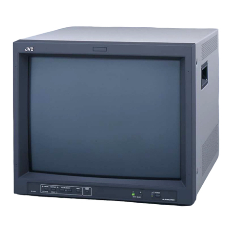
JVC TM-1400U(CV) User manual

TM-1400U(CV)
Ш
SPECIFICATIONS
та
И
SI
NET
S
SI
GR
ЊЕ
SQA
SRST
SS
RU
ы
ва
Буз
a
a
SE
2
Ш:
SAFETY
PRECAUTIONS
А
ДРИНИ
аа
а
ваге
S
AUS
IE
ж.алыага
љута
3
Ш
OPERATING
INSTRUCTIONS
с
сасе
с
а
ip
ey
HO
TOG
EG
wee
Rh
he
ER
ша
sa
a
ез
4
Ш
SPECIFIC
SERVICE
INSTRUCTIONS...
...
0...
8
B'SERVICEADJUSTMENT
S
а
ығы
OU
©
c
Shah
i
Rn
REO
RI
EN
SISSE
11
M
PARTS
ШӘТ
ai
aa
IE
EMEN
TR
Vaikas
ит
ти
и
и
s m
RR.
19
Ш
SCHEMATIC
DIAGRAM(APPENDED)
.........................................
0-0
Мо.50353
COPYRIGHT
©
1990
VICTOR
COMPANY
OF
JAPAN,LTD.
Jan.1990

1
MI
18UUU(UV)
|
SPECIFICATIONS
Dimensions
36.5ст(У/)
x
39.4cm(D)
x
33.4cm(H)
Weight
15.9kg
Color
system
NTSC
system
Power
Input
AC
120V,60Hz
Power
consumption
Max.
1.05A,Avg.
60W
Picture
Tube
14"
(measured
diagonally),90°
deflection,in-Line
gun,data
grade
tinted
CRT
tri-dot
pitch
0.499mm
Screen
size
284mm(H)
x
213mm(V)
Scanning
frequency
(H)
15.75KHz
(V)
60Hz
High
voltage
24kV(at
zero
beam
current)
Horizontal
resolution
More
than
450
lines
VIDEO
IN/OUT
BNC
x
2(IN/OUT),Bridged
connection
is
possible.
(Termination
switch
provided)
VS-1Vp-p,75fl,negative
ACCESSORY
Power
cord(approx.
2.4m)
X
1
Design
&
specification
subject
to
change
without
notice.
2
(No.50353)

SAFETY
PRECAUTIONS
10.
The
design
of
this
product
contains
special
hardware,
many
circuits
and
components
specially
for
safely
purposes.
For
continued
pro-
tection,no
changes
should
be
made
to
the
original
design
unless
authorized
in
writing
by
the
manufacturer.
Replacement
parts
must
be
identical
to
those
used
in
the
original
circuits.
Service
should
be
performed
by
qualified
personnel
only.
Alterations
of
the
design
or
circuitry
of
the
products
should
not
be
made.
Any
design
alterations
or
additions
will
void
the
manufactur-
er's
warranty
and
will
further
relieve
the
manufacturer
of
responsi-
bility
for
personal
injury
or
property
damage
resulting
therefrom.
Many
electrical
and
mechanical
parts
in
the
products
have
special
safety-related
characteristics.
These
characteristics
are
often
not
evident
from
visual
inspection
nor
can
the
protection
afforded
by
them
necessarily
be
obtained
by
using
replacement
components
tated
for
higher
voltage,
wattage,
etc.
Replacement
parts
which
have
these
special
safety
characteristics
are
identified
in
the
parts
list
of
Service
manual.
Electrical
components
having
such
fea-
tures
are
identified
by
shading
on
the
schematics
and
by
(A)
on
the
parts
list
in
Service
manual.
The
use
б!
a
substi-
tute
replacement
which
does
not
have
the
same
safety
characteris-
tics
as
the
recommended
replacement
part
shown
in
the
parts
list
of
Service
manual
many
create
shock,
fire,
or
other
hazards.
Use
isolation
transformer
when
hot
chassis.
The
chassis
and
any
sub-chassis
contrained
in
some
products
are
connected
to
one
side
of
the
AC
power
line.
An
isolation
transform-
er
of
adequale
capacily
should
be
inserted
between
the
product
and
the
AC
power
supply
point
while
performing
any
service
on
some
products
when
the
HOT
chassis
is
exposed.
Don't short
between
the
LIVE
side
ground
and
NEUTRAL
side
grounding
or
EARTH
side
ground
when
repairing.
Some
model's
power
circuit
is
partly
different
in
the
GND.
The
dif-
ference
of
the
GND
is
shown
by
the
LIVE
(L)
side
GND,
the
NEU-
TRAL
tzr)
side
GND
and
EARTH
(Q)
side
GND.
Don't
short
be-
tween
the
LIVE
side
GND
and
NEUTRAL
side
GND
or
EARTH
side
GND
and
never
measure
with
a
measuring
apparatus
(oscilloscope
etc.)
the
LIVE
side
GND
and
NEUTRAL
side
GND
or
EARTH
side
GND
at
the
same
time.
If
above
note
will
not
be
kept,
a
fuse
or
any
parts
will
be
broken.
If
any
repair
has
been
made
to
the
chassis,
it
is
recommended
that
the
B,
setting
should
be
checked
or
adjusted
(See
ADJUSTMENT
OF
Ву
POWER
SUPPLY).
š
The
high
voltage
applied
to
the
picture
tube
must
conform
with
that
specified
in
Service
manual.
Excessive
high
voltage
can
cause
an
increase
in
X-Ray
emission,
arcing
and
possible
component
dam-
age,
therefore
operation
under
excessive
high
voltage
conditions
should
be
kept
to
a
minimum,
or
should
be
prevented.
If
severe
аг-
cing
occurs,
remove
the
AC
power
immediately
and
determine
the
cause
by
visual
inspection
(incorrect
installation,
cracked
or
melted
high
voltage
harness,
poor
soldering,
etc.).
To
maintain
the
proper
minimum
level
of
soft
X-Ray
emission,
components
in
the
high
volt-
age
circuitry
including
the
picture
tube
must
be
the
exact
replace-
ments
or
alternatives
approvided
by
the
manufacturer
of
the
com-
plete
product.
Do
not
check
high
voltage
by
drawing
an
arc.
Use
a
high
voltage
meter
or
a
high
voltage
probe
with a
VTVM.
Discharge
the
picture
tube
before
attempting
meter
connection,
by
connecting
a
clip
lead
to
the
ground
frame
and
connecting
the
other
end
of
the
lead
through
а
10КЯ
2W
resistor
to
the
anode
button.
When
service
is
required,
observe
the
original
lead
dress.
Extra
pre-
caution
should
be
given
to
assure
correct
lead-dress
in
the
high
voltage
circuit
area.
Where
a
short
circuit
has
occurred,
those
com-
ponents
that
indicate
evidence
of
overheating
should
be
replaced.
Always
use
the
manufacturer's
replacement
components.
Isolation
Check
(Safety
for
Electrical
Shock
Hazard)
After
re-assembling
the
product,
always
perform
an
Isolation
check
(1)
(2)
11.
TM-140UU(UV)
on
the
exposed
metal
parts
of
the
cabinet
(antenna
terminals,
vid-
eo/audio
input
and
oulput
terminals,
Control
knobs,metal
cabinet,
screwheads,
earphone
jack,
control
shafts,
etc.)
to
be
sure
the
prod-
uct
is
safe
to
operate
without
danger
of
electrical
shock.
Dielectric
Strength
Test
The
isolation
between
the
AC
primary
circuit
and
all
metal
parts
ex-
posed
to
the
user,
particularly
any
exposed
metal
part
having
a
re-
turn
path
to
the
chassis
should
withstand
a
voltage
of
1100V
AC
(r.m.s.)
for
a
period
of
one
second.
(....
Withstand
a
voltage
of
1100V
AC
(r.m.s.)
10
an
appliance
rat-
ed
up
to
120V,
and
3000V
AC
(r.m.s.)
to
an
appliance
raled
200V
or
more,
for
a
period
of
one
second.)
This
method
of
test
requires
a
test
equipment
not
generally
found
in
the
service
trade.
Leakage
Current
Check
Plug
the
AC
line
cord
directly
into
the
AC
outlet
(do
not
use
a
line
isolation
transformer
during
this
check.)
Using
a
"Leakage
Current
Tester",
measure
the
leakage
current
from
each
exposed
metal
part
of
the
cabinet,
particularly
any
exposed
metal
part
having
a
return
path
to
the
chassis,
to
a
known
good
earth
ground
(water
pipe,
elc.).
Any
leakage
current
must
not
exceed
0.5mA
AC
(r.m.s.).
•
Alternate
Check
Method
Plug
the
AC
line
cord
directly
into
the
AC
outlet
(do
not
use
a
line
isolation
transformer
during
this
check.).
Use
an
AC
voltmeter
hav-
ing
1,000
ohms
per
volt
or
more
sensitivity
in
the
following
manner.
Connect
а
1,5002
10W
resistor
paralleled
by
а
0.15pF
AC-type
ca-
pacitor
between
an
exposed
metal
part
and
a
known
good
earth
ground
(water
pipe,
etc.).
Measure
the
AC
voltage
across
the
resis-
tor
with
the
AC
voltmeter.
Move
the
resistor
connection
to
each
ex-
posed
metal
part,
particularly
any
exposed
metal
part
having
a
re-
turn
path
to
the
chassis,
and
measure
the
AC
voltage
across
the
re-
sistor.
Now,
reverse
the
plug
in
the
AC
outlet
and
repeat
each
mea-
surement,
Any
voltage
measured
must
not
exceed
0.35V
AC
(r.m.s.).
This
corresponds
to
0.5mA
АС
(r.m.s.).
AC
VOLTMETER
(HAVING
10002/V,
OR
MORE
SENSITIVITY)
PLACE
THIS
PROBE
ON
EACH
EXPOSED
METAL
PART
15002
10W
GOOD
EARTH
GROUND
High
voltage
hold
down
circuit
check.
After
repair
of
the
high
voltage
hold
down
circuit,
this
circuit
shall
be
checked
to
operate
correctly.
See
item
"How
to
check
the
high
voltage
hold
down
circuit”.
Ш
ONLY
CANADA
This
mark
shows
a
fast
operating
fuse,
the
letters
indicated
below
show
the
rating.
q
(No.50353)
3

(ESE0S'ON)
+
4
INSTRUCTIONS
JVC
TM-1400U(CV)
COLOR
VIDEO
MONITOR
SNOILORH.ISNI
9NI.LVH3dO

S
(29209
0М)
Thank
you
for
purchasing
а
JVC
color
video
monitor,
Your
new
monitor
will
provide
superior
quality
pictures
and
incorporates
many
useful
functions.
To
ensure
a
complete
understanding
of
the
monitor
and
to
extend
its
service
life,
please
read
all
instructions
in
this
booklet
and
keep
it
in
a
safe
place
for
future
reference.
•
14-Inch
data-grade
CRT,
together
with
а
comb
filter
for
pictures
with
a
horizontal
resolution
of
more
than
450
lines.
•
Video
input
terminal
with
bridged
connection
capability,
convenient
monitoring
between
two
video
sources
when
dubbing.
•
Mountable
in
a
standard
EIA
rack
with
optional
rack
mount
adapter
RK-150E,
(For
mounting,
refer
to
the
In“
struction
manual
of
the
RK-150E.)
CAUTION:
_
TO
REDUCE
THE
RISK
OF
ELECTRIC
SHOCK.
DO
NOT
REMOVE
COVER
(ОА
BACK).
NO
USERSEAVICEABLE
PARTS
INSIDE.
REFER
SERVICING
TO
QUALIFIED
SERVICE
PERSONNEL.
The
lightning
flash
with
arrowhead
symbol,
within
an
equilateral
triangle
is
intended
to
alert
the
user
to
the
presence
of
uninsulated
"dangerous
voltage'"
within
the
product's
enclosure
that
may
be
of
sufficient
magni-
tude
to
constitute
a
risk
of
electric
shock
to
persons.
The
exclamation
point
within
an
equilateral
triangle
is
intended
to
alert
the
user
to
the
Presence
of
important
operating
and
main-
tenance
(servicing)
instructions
in
the
litera-
ture
accompanying
the
appliance.
SAFETY
PRECAUTIONS
Safety
Precautions
.......
Controls
and
Connectors
...
Connections
...
Specifications
..
an
an
In
order
to
prevent
any
fatal
accidents
caused
by
misoperation
or
mishandling
of
the
monitor,be
fully
aware
of
all
the
follow-
ing
precautions.
WARNINGS
To
prevent
fire
or
shock
hazard,
do
not
expose
this
monitor
to
rain
or
moisture.
Dangerous
high
voltages
are
present
inside
the
unit
Do
not
remove
the
back
cover
of
the
cabinet.
When
servicing
the
monitor,
contact
qualified
service
personnel.
Never
try
to
service
it
yourself.
INFORMATION
Caution:
Changes
or
modification
not
approved
by
JVC
could
void
the
user's
authority
to
operate
the
eguip-
ment.
NOTE:
This
equipment
has
been
tested
and
found
to
comply
with
the
limits
for
a
Class
B
digital
device,
pur-
suant
to
Part
15
of
the
FCC
Rules.
These
limits
are
designed
to
provide
reasonable
protection
against
harmful
interference
in
a
residential
installation.
This
equipment
generates,
uses
and
can
radiate
radio
fre-
quency
energy
and,
if
not
installed
and
used
in
ac-
cordance
with
the
instructions,
may
cause
harmful
interference
to
radio
communications,
However,
there
is
no
guarantee
that
interference
will
not
occur
in
a
particular
installation.
М
this
equipment
does
cause
harmful
interference
to
radio
or
television
reception,
which
can
be
determined
by
turning
the
equipment
off
and
on,
the
user
is
encouraged
to
try
to
correct
the
interference
by
one
or
more
of
the
following
measures:
—
Reorient
or
relocate
the
receiving
antenna.
—
|ncrease
the
separation
between
the
equipment
and
receiver.
—
Connect
the
equipment
into
an
outlet
on
a
circuit
different
from
that
to
which
the
receiver
is
connected.
This
monitor
is
equipped
with
a
3-blade
grounding-type
plug
to
satisfy
FCC
rule.
If
you
are
unable
to
insert
the
plug
into
the
outlet,
contact
your
electrician.
PRECAUTIONS
Use
only
the
power
source
specified
on
the
rating
label
located
on
rear
of
the
cabinet.
~
When
not
using
this
unit
(ог
а
long
period
of
time,
ог
when
cleaning
it,
be
sure
to
disconnect
the
power
plug
from
the
AC
outlet.
Do
not
allow
anything
to
rest
on
the
power
cord.
And
do
not
locate
this
unit
where
people
will
tread
on
the
cord.
Do
not
overload
wall
outlets
or
power
cords
as
this
can
result
in
a
fire
or
electric
shock.
Avoid
using
this
unit
under
the
following
conditions:
—
in
extremely
hot,
cold
or
humid
places,
一
in
dusty
places,
—
near
appliances
generating
strong
magnetic
fields,
—
in
places
subject
to
direct
sunlight,
and
—
in
badly
ventilated
places.
Do
not
cover
the
ventilation
slots
while
in
operation
as
this
could
obstruct
the
required
ventilation.
When
dust
accumulates
on
the
screen
surface,
clean
with
а
soft
cloth.
Unplug
this
unit
from
the
AC
outlet
and
refer
servicing
to
qualified
service
personnel
under
the
following
conditions:
—
When
the
power
cord
is
frayedor
plug
is
damaged.
—
If
liquid
has
been
spilled
into
the
unit.
—
If
the
unit
does
not
operate
normally
following
the
op-
erating
instructions,
—
If
the
unit
has
been
dropped
or
the
cabinet
has
been
damaged.
—
When
the
unit
exhibits
a
distinct
change
in
perform-
ance.
Do
not
attempt
to
service
this
unit
yourself
as
opening
or
removing
covers
may
expose
you
to
dangerous
voltage
or
other
hazards.
Always
refer
servicing
to
qualified
service
personnel.
When
replacement
parts
are
required,
have
the
service
per-
sonnel
verify
in
writing
that
the
replacement
parts
he
uses
have
the
same
safety
characteristics
as
the
original
parts.
Use
of
manufacturer's
specified
replacement
parts
can
pre-
vent
fire,
shock,
or
other
hazards.
Upon
completion
of
any
servicing
or
repair
to
this
unit,
please
ask
the
service
personnel
to
perform
the
safety
check
described
in
the
manufacturer's
service
literatur
When
this
unit
reaches
the
end
of
its
useful
li
improper
disposal
could
result
in
a
picture
tube
implosion.
Ask
qualified
service
personnel
to
dispose
of
this
unit.
Laml\annet
cial!

(55505'0№)
9
(Front
Panel)
CHROMA
BRIGHT
CONTRAST
(Rear
Panel)
oren
(CEB)
sn.
0
У.
HOLD
control
Turn
the
adjust
the
vertical
synchronization
of
the
picture.
@
Picture
controls
Use
to
optimize
the
picture.
The
center
click
position
of
each
control
is
its
standard
setting.
This
standard
setting
can
be
varied
(preset)
by
turning
the
SUB
control
screws
at
the
side
of
the
controls.
Use
a
screwdriver
to
turn
the
SUB
controls,
•
PHASE
control
Turn
to
adjust
the
picture
hue,
Adjust
with
reference
to
skin
color.
•
CHROMA
control
Turn
to
adjust
the
color
density
of
the
picture
to
your
preference.
*
BRIGHT
control
Turnto
adjustthe
picture
brightness
to
your
preference.
*
CONTRAST
control
Turn
to
adjust
the
picture
contrast
to
your
preference.
©
POWER
switch/indicator
Pressing
this
switch
turns
the
power
on;
the
indicator
lights.
Pressing
this
switch
again
turns
the
power
off;
the
indicator
goes
off.
Q
Power
input
connector
Connect
to
an
AC
outlet
with
the
provided
power
cord.
©
INPUT
connectors/Termination
switch
Input
connector
for
composite
video
signal
and
output
connector
for
bridge-connected
signal
IN
:
When
inputting
a
signal
OUT
:
For
bridged
connection
Setting
the
termination
switch
750
:
When
there
is
only
an
input
signal
OPEN
:
For
bridged
connection
Q
SET
UP
switch
Do
not
reset
this
switch,
It
is
for
service
personnel
only.
*
Be
sure
to
disconnect
the
power
plug
from
the
AC
outlet
before
connecting
to
other
equipment.
*
Also
refer
to
the
instruction
manual
of
the
equipment
to
be
connected.
Videodisc
player
Control
console
Control
console
Video
monitor
*
When
using
any
of
the
OUT
connectors
(bridged
output),
set
its
termination
switch
to
"OPEN".

Туре
:
Color
video
monitor
Color
system
:
NTSC
system
CRT
:
14"
(measured
diagonally),
90°
deflection,
In-line
gun,
data-grade
tinted
CRT,
dot
pitch
0.499
mm
Screen
size
(H
x
V)
:
284
x
213
тт
Scanning
frequency
:
(H)
15.75
kHz
(V)
60 Hz
Horizontal
resolution
:
More
than
450
lines
Power
requirement
:
AC
120
V,
60 Hz
Power
consumption
:
Мах.
1,05
A,
Avg.
60
W
INPUT
:
VIDEO-BNC
x
2
.
VS—1
Vp-p,
75
f1,
negative
Bridged
connection
possible
(Termination
switch
provided)
Weight
115.9
kg
Accessory
:
Power
cord
(approx.
2.4
т)
x
1
Dimensions
(Unit:
mm)
Design
and
specifications
subject
to
change
without
notice
(AD)
NOOPL-WL

ИУ]
|
SPECIFIC
SERVICE
INSTRUCTIONS
DISASSEMBLY
PROCEDURE
1.
Method
of
removing
the
top
cover
(1)
Remove
the
two
screws
A
in
Fig.
1.
(2)
Remove
the
respectively
two
screws
®
and
©.
(3)
Ву
pulling
the
cover
a
little
bit
backward,
dismount
the
ТІ
>
ет.
|
ФА
T
ТШ
cover
as
indicated
by
ап
arrow.
1
IT
III
ІШ
III
Also
remove
the
screw
on
the
opposite
side.
Fig.
1
2.
Method
of
dismounting
the
rear
cover
*
Dismount
the
top
cover.
V)
Remove
ha
two
screws
Org.
El
a
7”
ШО
УУ
(2)
Pull
the
rear
cover
right
upward
until
it
stops
as
indicated
by
the
arrow,
and
dismount
the
cover.
For
assembly,
(1)
Since
the
four
positions
©
in
Fig.
2-2
are
hooked,
align
the
hooks
straight
and
let
them
move
down.
B
(No.50353)

3.
Method
of
dismounting
Input
PCB
e
e
(1)
(2)
(3)
(4)
Dismount
the
top
cover.
Dismount
the
rear
cover.
Remove
the
three
screws
©
in
Fig.
3.
Remove
the
GND
wire.
When
the
two
hooks
between
the
Main
and
Input
PCBs
are
removed,
the
Input
PCB
will
be
dismounted.
Dismount
the
connectors,
etc.
as
required.
4.
Method
of
dismounting
Power
PCB
(1)
Dismount
the
top
cover.
Remove
the
wire
clamp
fixing
the
transformer
on
the
Power
PCB
and
PCB
holder.
Remove
the
four
screws
©
in
Fig.
4
and
dismount
the
PCB
holder.
Remove
the
two
screws
©.
After
raising
the
Power
PCB
once,
pull
the
lower
part
of
the
PCB
outward
and
dismount
the
PCB.
Dismount
the
connectors,
etc.
as
required.
5.
Method
of
checking
the
Main
PCB
(1)
(2)
(3)
Dismount
the
top
cover.
Dismount
the
rear
cover.
Set
the
TV
set
sideways
as
shown
in
Fig.
5.
In
this
case,
lay
soft
cloth,
etc.
under
the
set
in
advance
to
prevent
any
damage
to
the
exterior
part.
Remove
the
four
screws
(D
and
dismount
the
bottom
lid.
Shift
the
Main
PCB
as
required.
ТМ
ИЛА
У
]
ШИШИШИ
!Ə/%IIIxIƏIIXIEIƏIIIIRVQWDTÑIçMIIIII
О
о
ШОУ
И
ШШШ
Ж
ИТ
Fig.
5
(Bottom
surface
view)
(Мо.50353)
9

кыы,
54
|
6.
Method
of
dismounting
front
panel
ass'y
*
Dismount
the
top
cover.
*
Dismount
(һе
rear
cover.
(1)
Remove
the
chord
of
degauss
coil
(Power
PCB
[I]).
(2)
Remove
the
two
chords
of
deflecling
coil
(Main
PCBs
[H]
and
[V)).
(8)
Remove
the
anode
cap.
+
Pay
attention
to
the
high
tension!!
Since
the
cap
will
be
electrified,
bė
sure
to
remove
the
cap
after
discharging.
(4)
After
removing
the
[CRT
EARTH]
chord,
pull
out
the
CRT
socket
PCB.
(5)
When
the
four
screws
©
are
removed,
the
front
panel
ass'y
will
be
dismounted
together
with
the
CRT.’
e
Since
the
CRT
is
heavy,
remove
the
screws
O)
while
holding
the
front
panel
ass'y.
7.
Precautions
for
wire
clamp
and
binding
band
(1)
The
wire
should
be
clamped
exactly.
(2)
Be
sure
not
to
remove
the
binding
band
for
wire
treatment.
Should
it
be
removed,
the
wire
should
be
treated
exactly
to
the
initial
position.
10
(Мо.50353)
Chord
of
degauss
coil
Anode
cap
Pay
attention
to
high
tensionl!
Chord
of
deflecting
coil
Fig.
6-1
Use
the
long
screw
driver.
The
screw
driver
is
accessible
from
here.
Fig.
6-2

ee
SERVICE
ADJUSTMENTS
PRIOR
TO
STARTING
TOOLS
AND
FIXTURES
FOR
ADJUSTMENT
ADJUSTMENT
Dismount
the
top
cover,
rear
cover
and
bottom
lid.
+
DC
voltmeter
or
digital
voltmeter
Perform
sufficient
warm-up
of
the
TV
зе!
and
testers.
*
Oscilloscope
(for
30
minutes
or
more).
°
Pattern
generator
(NTSC)
+
Unless
specified
otherwise
specially
in
[ADJUSTING
STEP]
*
If
monoscope
signal
can
be
output,
it
is
possible
to
perform
given
below,
perform
adjustment
after
setting
the
switches
further
accurate
adjustment.
and
VRs
on
the
front
panel
to
the
following
positions:
+
The
signal
should
be
input
to
VIDEO
А.
CONTRAST
:
CLICK
position
*
Color
thermometer
BRIGHT
:
CLICK
position
+
Adjustment
is
possible
without
it.
If
available,
however,
CHROMA
:
CLICK
position
further
accurate
adjustment
is
possible.
PHASE
:
CLICK
position
е
Short
jumper
e
Regarding
the
list
of
the
layout
of
adjusted
parts,
refer
to
•
10k
resistor
[ADJUSTMENT
LOCATION]
in
[SCHEMATIC
DIAGRAM}.
In
addition
to
the
above,
the
following
tools
are
necessary
to
adjust
the
purity
and
convergence.
e
Magnelic
eraser
e
Silicon
bond
(KE4866)
e
REICHLOCK
ог
G2
bond
ADJUSTING
STEP
POWER
PCB
Measuring
i
Adjustment
Adjustment
of
PATTERN
TP-91
R913
B1
VOLTAGE
GENERATOR
.
Input
the
total
black
signal.
2.
Adjust
the
B1
adjust
VR
(R913)
so
that
the
voltage
between
TP-91
and
ТР-Е
(-)
becomes
ОС
110V.
3.
Confirm
that
the
B1
voltage
scarcely
changes
even
when
the
input
signal
has
been
changed.
DC
VOLTMETER
or
DIGITAL
VOLTMETER
POWER
PCB
(Мо.50353)
11

MAIN
PCB
(1)
чеп
ТР-64
7301
.
Input
the
color
bar
signal.
2.
Connect
the
oscilloscope
boten
TP-64
and
ТР-Е.
In
case
(һе
waveform
can
be
expanded
by
the
oscilloscope,
expand
the
waveform
to
allow
easy
adjustment.
9.
Adjust
the
DL
PHASE
VR
(T301)
so
that
the
CHROMA
component
becomes
minimum.
4.
With
the
COMB
VR
(R312),
adjust
the
CHROMA
component
so
that
the
component
becomes
minimum.
.
Repeat
Steps
3
and
4.
Measuring
instrument
PATTERN
GENERATOR
Adjustment
of
NTSC
COMB
LINE
FILTER
OSCILLOSCOPE
MAIN
PCB
Minimize
the
CHROMA
component
Expansion
of
waveform
Adjustment
of
NTSC
COLOR
SYNCHRONISM
PATTERN
GENERATOR
.
Input
the
color
bar
signal.
-
Connect
TP-43B
and
TP-E
with
a
short
jumper.
-
Connect
TP-40
and
TP-92
with
a
10kQ
resistor.
-
Adjust
the
COLOR
SYNC.
VR
(C320)
to
a
position
where
the
color
changes
from
a
striped
‘pattern
to
a
color
bar
and
remains
at
a
standstill.
There
will
bé
no
problem
if
the
color
of
color
bar
being
displayed
on
the
screen
is
different
from
that
of
the
color
bar
signal
being
input.
5.
Remove
the
connected
short
jumper
and
resistor.
6.
Make
sure
that
the
color
synchronism
is
not
collapsed
and
instantaneously
led
in
when
returned
to
the
color
bar
signal
again
after
changing
(ће
input
select
Switch.
һо
№
=
SHORT
JUMPER
10
КО
RESISTOR
“MAIN
PCB
ТР-438
=
ЫЕ
-40
e
TP-92
ФТР-Е
12
(Мо.50353)

меншш;
Description
CRT
socket
PCB
Measuring
Adjustment
Adjustment
of
PATTERN
А705
:R
Continue
running
for
10
minutes
or
more.
CUTOFF
GENERATOR
R715:G
1.
Input
the
total
white
signal.
R725
:B
2.
Turn
the
transverse
one
line
[SET
UP]
switch
(S203)
SCREEN
VA
on
the
rear
surface
over
(о
the
[SET
UP]
side.
3.
Turn
the
[CUT
OFF]
VRs
(R705,
R715
and
R725)
on
the
CRT
socket
PCB
fully
in
counterclockwise
@
R725
:B
direction.
@R715:G
о
4.
While
turning
the
screen
VR
gradually
in
clockwise
о
МАМ
РСВ
direction
from
full
counterclockwise
direction,
search
@R705:R
for
the
color
appearing
for
the
first
time.
5.
Turn
the
[CUT
OFF]
VRs,
with
which
the
color
has
appeared
first
in
the
Step
4,
slightly
in
clockwise
direction.
6.
By
turning
the
[CUT
OFF]
VRs
for
the
other
two
colors
in
clockwise
direction,
adjust
the
intensity
of
the
three
shining
colors
so
that
the
transverse
single
line
look
white.
7.
Return
the
transverse
single
line
[SET
UP]
switch
(S203)
to
the
[NORMAL]
side.
О
Т
socket
PCB
о
СВ
РАТТЕАМ
GENERATOR
Adjustment
of
R702
:R
DRV
R712
:G
DRV
Continue
running
for
30
minutes
or
more.
•
This
adjustment
should
be
performed
after
[Adjustment
of
CUTOFF].
1.
Input
the
total
white
signal.
2.
Adjust
the
В
and
G
DRIVER
VRs
(R702
and
А712)
on
the
CRT
socket
PCB
to
a
position
where
the
entire
screen
becomes
white.
3.
While
turning
the
CONTRAST
VR
and
BRIGHT
VR
on
the
front
panel,
make
sure
that
the
white
balance
is
attained.
O
S°
o
CRT
socket
PCB
Ф
R712
:G
DRV
5702
:R
DRV
[In
case
monoscope
signal
and
color
temperature
meter
are
available]
1.
Input
the
monoscope
signal.
2.
The
light
receiving
unit
of
the
color
temperature
meter
will
measure
the
color
temperature
at
the
center
of
the
screen.
3.
Adjust
the
CONTRAST
VR,
R
and
G
DRIVER
VRs
(R702
and
R712)
on
the
CRT
socket
PCB
to
a
position
where
the
color
temperature
meter
indicates
a
specified
value.
•
Color
temperature
:
D9300*K
(х=0.283,
y
20.297)
While
turning
the
CONTRAST
VR
and
BRIGHT
VR
on
the
front
panel,
make
sure
that
the
white
balance
is
attained.
e
(No.50353)
13

`
,
MAIN
PCB
(2)
ө:
аш
Description
Continue
running
for
30
minutes
or
more.
•
This
adjustment
should
be
performed
after
[Adjustment
of
CUTOFF].
e
Set
the
CONTRAST
and
BRIGHT
VRs
on
the
front
panel
to
the
clicking
position.
1.
Input
the
color
bar
signal.
2.
Turn
the
V.
HOLD
МА
to
display
the
vertical
flyback
time
and
let
it
remain
at
a
standstill.
3.
Adjust
the
SUB
BRIGHT
VR
(R269)
in
front
of
the
position
where
the
vertical
flyback
time
becomes
black
(In
this
case,
be
careful
so
that
it
will
not
become
too
bright).
4.
Adjust
the
vertical
synchronism
with
the
V.
HOLD
VR.
Measuring
PATTERN
GENERATOR
Adjustment
of
SUB
BRIGHT
Vertical
flyback
time
•
This
adjustment
should
be
performed
after
[Adjustment
of
SUB
BRIGHT]
•
Set
the
CONTRAST
and
BRIGHT
VRs
on
the
front
panel
to
the
clicking
position.
1,
Input
the
color
bar
signal
(including
100%
white
signal).
2.
Turn
the
CHROMA
VR
on
the
front
panel
and
turn
the
screen
to
black
and
white.
3.
Connect
the
oscilloscope
between
TP-47B
and
TP-E
on
the
CRT
socket
PCB.
4.
Adjust
the
SUB
CONT.
VR
(R265)
so
that
the
voltage
of
the
waveform
becomes
47.5Vg
w-
5.
Release
the
CHROMA
VR
on
the
front
panel
to
return
the
screen
to
color.
Standard
setting
|
PATTERN
of
CONTRAST
GENERATOR
OSCILLOSCOPE
This
adjustment
should
be
performed
after
[Adjustment
of
CONTRAST]
•
Set
all
the
VRs
on
the
front
panel
to
the
clicking
position.
1.
Input
the
color
bar
signal.
2.
Connect
the
oscilloscope
between
TP-47B
and
TP-E
on
the
CRT
socket
PCB.
3.
Align
the
waveforms
1
and
3
in
the
diagram
below
with
the
SUB
PHASE
VR
(R345)
4.
Align
the
waveforms
1
and
4
in
the
diagram
below
with
the
SUB
CHROMA
VR
(R348)
5.
By
repeating
the
Steps
3.and
4,
align
the
waveforms
1
-
4
to
the
same
level.
PATTERN
-
GENERATOR
Adjustment
of
CHROMA
and
PHASE
(NTSC)
OSCILLOSCOPE
R265
R348
R269
R345
MAIN
PCB
CRT
socket
PCB
14
(No.50353)

Adjustment
part
Measuring
г
instrument
|
Test
point
Description
Adjustment
of
PATTERN
FOCUS
GENERATOR
FOCUS
VR
This
adjustment
should
be
performed
after
[Standard
setting
of
CONTRAST].
1.
Input
the
cross
hatch
signal.
2.
Adjust
the
FOCUS
VR
to
a
position
where
the
vertical
and
horizontal
lines
of
cross
hatch
become
thinnest
and
clearest.
Note:
Be
sure
to
perform
final
adjustment
of
the
convergence
after
adjustment
of
focus,
since
the
convergence
will
be
changed
whenever
the
focus
has
been
adjusted.
Both
the
vertical
and
horizontal
lines
should
be
made
thin.
PATTERN
GENERATOR
Adjustment
of
HORIZONTAL
SYNCHRONISM
Set
the
CONTRAST
VR
on
the
front
panel
to
the
clicking
position.
1.
Input
the
color
bar
signal.
2.
Connect
TP-33A
and
TP-E
with
a
short
jumper.
3.
Adjust
the
H.
HOLD
VR
(8505)
to
a
position
where
the
image
remains
at
a
standstill
without
flowing
horizontally.
•
Матеју,
adjust
the
VR
to
an
intermediate
position
where
the
image
flows
horizontally.
4.
Remove
the
connected
short
jumper.
5.
Make
sure
that
the
color
synchronism
is
not
collapsed
and
normal
image
appears
instantaneously
when
returned
to
the
color
bar
signal
again
after
changing
the
input
select
switch.
SHORT
JUMPER
MAIN
PCB
(No.50353)
15

UU
IC
V)
Measuring
Adjustment
ot
PATTERN
Adjustment
part
•
This
adjustment
should
be
performed
after
H.
ANPLITUDE
GENERATOR
[Adjustment
of
B1
VOLTAGE]
and
[Adjustment
hri
of
HORIZONTAL
SYNCHRONISM].
H.
CENTER
1.
Input
the
monoscope
signal
or
cross
hatch
signal.
2.
With
the
horizontal
amplitude
coil
(L501)
and
[H.
CENTER]
switch
(5501),
perform
adjustment
so
that
95%
of
monoscope
pattern
(cross
hatch)
is
displayed
on
the
screen.
MAIN
PCB
PATTERN
GENERATOR
Adjustment
of
.
Input
the
monoscope
signal
or
cross
hatch
signal.
V.
AMPLITUDE,
У.
CENTER
and
V.
LINEARITY
2.
Roughly
adjust
the
V.
HEIGHT
VR
(R413)
so
that
nearly
all
the
monoscope
pattern
(cross
hatch)
is
displayed
on
the
screen.
3.
With
the
V.
HEIGHT
VR
(R413)
and
V.
CENTER
switch
(S401),
perform
adjustment
so
that
95%
of
the
monoscope
pattem
(cross
hatch)
is
displayed
on
the
screen.
4.
While
turning
the
V.
LIN.
VR
(R409),
adjust
the
vertical
linearity.
.
Repeat
the
Steps
2
-
4
as
required.
MAIN
PCB
95%
[OVER
SCAN]
screen
16
(No.50353)

ADJUSTING
STEP
OF
COLOR
ТОМЕ
ADJUSTMENT
OF
PURITY
Adjustment
Part
Wedge
Purity
magnet
G
cutoff
VR
R
cutoff
VR
B
cutoff
VR
Screen
VR
Deflecting
yoke
Traverse
one
line
[SET
UP]
switch
Description
PRIOR
TO
STARTING
ADJUSTMENT:
1.
Remove
the
wedge
being
inserted
in
between
the
deflecting
yoko.
At
this
time,
clear
the
trace
of
the
wedge.
Peel
off
the
adhesive
fixing
six
magnets
with
the
бр
of
screw
driver,
etc.
so
that
the
magnets
will
turn
freely.
Input
the
total
while
signal,
Perform
magnetic
erasing
of
the
Brown
tube
with
а
magnelic
eraser.
Set
the
brightness
and
picture
to
slightly
higher
levels,
and
perform
warm-up
roughly
for
20
-
30
minutes.
ADJUSTING
STEP
1.
By
turning
the
G
CUTOFF
VR
on
the
CRT
socket
board
fully
in
clockwise
direction
and
the
R
and
B
CUTOFF
VR
fully
in
counterclockwise
direction,
adjust
the
screen
VR
to
make
the
green
screen
visible.
After
loosening
the
clamp
screw
of
the
deflecting
yoke,
pull
the
yoke
fully
backward,
and
let
color
shading
appear
in
a
vertical
belt
form.
Pile
up
the
clicks
of
the
two
purity
magnets
alternately
each
other,
and
set
ithem
to
a
horizontal
position
as
an
initial.
While
opening
and
closing
or
turning
the
clicks
of
the
two
purity
magnets,
perform
adjustment
so
that
the
green
vertical
belt
appears
at
the
center
of
the
screen.
|
By
pushing
out
the
deflecting
yoke
10
the
front
side,
position
the
yoke
so
that
the
entire
screen
becomes
totally
green
(п
this
case,
tentatively
fix
the
deflecting
yoke
with
a
wedge
so
that
the
yoke
is
not
moved).
Set
the
traverse
one
line
[SET
UP]
switch
to
the
[SET
UP]
side
to
display
traverse
one
line
on
the
screen.
With
the
deflecting
yoke,
make
the
traverse
one
line
horizontal
and
further
close
to
the
vertical
center
(Do
not
change
the
cross
position
of
the
deflecting
yoke)
Return
the
transverse
single
line
[SET
UP]
switch
(о
the
[NORMAL]
side.
@
8
CUTOFF
V^
@GCUTOFF
>
@
R
CUTOFF
y^
О
CRT
socket
PCB
О
FX-3014A
Align
the
two
purity
magnets
to
a
horizontal
level.
Bring
the
green
belt
to
the
center.
Traverse
one
line
Vertical
center
position
(There
are
two
small
dents)
Let
the
traverse
one
line
approach
between
both
of
the
white
dents
denoted
byt
>
(№:50353)
17

Adjustment
tion
8.
Confirm
that
the
purity
has
been
attained
with
regard
to
the
red,
blue
and
monocolor
газ!ег5.
9.
Tentatively
lix
the
deflecting
yoke
slightly
with
the
clamp
screw
to
prevent
its
movement
in
back
and
forth
direction.
10.Reslore
the
wedges
to
the
initial
position
and
fix
the
deflecting
yoke.
Use
four
wedges
of
a
X-form
and
set
them
respectively
at
an
interval
of
about
90°.
The
wedges
should
be
fixed
to
the
Brown
tube
using
silicon
bond
(KE4866)
11.
The
clamp
screw
of
the
deflecting
yoke
should
be
clamped
firmly
with
and
adequate
torque.
The
wedges
should
be
fixed
at
four
positions
at
an
interval
of
about
90°.
ADJUSTMENT
OF
CONVERGENCE
.
Input
the
cross
hatch
signal.
оге
P
-
Overlap
the
red
and
blue
lings
at
the
center
of
the
screen
with
4-pole
magnet
to
turn
the
color
to
Magenta
color
(red/blue).
=
Turn
together
while
.
Next,
overlap
the
Magenta
color
(red/blue)
and
v4
Дед,
ће
|
1
angle
of
the
A
at
the
center
of
the
screen
with
6-pole
`
рады
„
Repeat
the
Steps
2
and
3,
and
adjust
the
convergence
of
the
vertical
and
horizontal
lines
at
the
center
of
the
screen.
AFTER
COMPLETION
OF
ADJUSTMENT
1.
Subsequent
to
completing
adjustment
of
the
purity
and
convergence,
fix
the
six
magnets
using
an
adhesive
(G2
bond
ог
REICHLOCK).
.
Then,
be
sure
to
adjust
the
boards
on
Page
1
-
13
and
after.
;
18
(No.50353)

PARTS
LIST
CAUTION
The
parts
marked
AN
are
very
important
for
the
safety.
When
replacing
these
parts,
be
sure
to
use
specified
ones
to
secure
the
safety
and
performance.
Ш
The
module
circuit
board
is
supplied
together
with
the
assembly,
bul
the
parts
which
do
not
have
the
drawing
in
this
Parts
List,
P.
C.
Board
Ass'y
and
the
Parts
No.
columns
of
which
are
filled
with
lines
—
.
will
not
be
supplied.
Ш
As
а
rule,
the
resistors
and
capacitors
which
are
indicated
as
shown
in
(NOTE
2)
"HOW
TO
EXPRESS
PARTS
NUMBERS
OF
STANDARD
PARTS"
are
not
shown
in
the
list
of
the
parts
on
the
board.
When
ordering
the
service
parts,
confirm
the
resistance/rated
power,
capacilance/raled
voltage,
and
type
of
the
parts,
then
order
by
the
part
No.
indicated
according
to
(NOTE
2).
(NOTE
1)
ABBREVIATIONS
OF
RESISTORS,
CAPACITORS
AND
TOLERANCES
CAPACITORS
RESISTORS
Carbon
Resistor
Fusible
Resistor
Plate
Resistor
Variable
Resistor
High
Voltage
Resistor
Melal
Film
Resistor
Metal
Glazed
Resistor
Metal
Plate
Resistor
Metal
Oxide
Film
Resistor
Coating
Metal
Film
Resistor
Non-Flammable
Resistor
Chip
Variable Resistor
Chip
Metal
Glazed
Resistor
Composition
Resistor
Linear
Positive
Temperature
Coefficient
Resistor
С
САР.
Е
САР.
М
САР.
НУ
САР.
МЕ
САР.
ММ
САР.
МР
САР.
РР
САР.
РЗ
САР.
ТЕ
САР.
МРР
САР.
ТАМ,
САР.
СН
С
САР.
ВР
Е
САР.
CH
AL
E
САР.
CH
AL
BP
CAP.
CH
TAN.
E
САР.
CH
AL
BP
E
САР.
Ceramic
Capacitor
Electrolytic
Capacitor
Mylar
Capacitor
High
Voltage
Capacitor
Metalized
Film
Capacitor
Metalized
Mylar
Capacitor
Melalized
Polystyrol
Capacitor
Polypropylene
Capacilor
Polystyrol
Capacilor
Thin
Film
Capacitor
Melalized
Polypropylene
Capacitor
Tantalum
Capacitor
Chip
Ceramic
Capacitor
Bi-Polar
Electrolytic
Capacitor
Chip
Aluminum
Electrolytic
Capacitor
Chip
Aluminum
Bi-Polar
Capacitor
Chip
Tantalum
Electrolytic
Capacitor
Chip
Tantalum
Bi-Polar
Electrolytic
Capacitor
+30%
+50%
+80%
+
100%
(7
10%
-
10%
|
-
20%
|-
0%
(Мо.50363)
19

ПУ
ГАЛАЛДА,У/
|
(МОТЕ2)
HOWTO
EXPRESS
PARTS
NUMBERS
ОҒ
STANDARD
PARTS
Су
ы
шн
Н
и
Cy
O
О
ж
ome
Kind
Rated
Power
Shape
Tolerance
Resistance
Ш
RESISTOR
Straight
lead
Chip
Symbol
Рап
|
Pari
Name
|
Symbol
COMP.R
less
than
10
О,
a
letter
"R"will
be
effective
as
point.
ЕХ.
220
=
282
4700
=
47х10!
—
471
150kQ
15x104
—
154
CH
MGR
ШСАРАСІТОН
E
ШЕ
Эме
=
Kind
Shape
Rated
Voltage
Tolerance
Capacitance
==
4
H
4
Indicate
with
first
two-figure
expressed
by
pF
following
0.
Please
note
that,in
case
of
capacitance
less
10
pF
a
letter
"А"
will
be
effective
as
point
EX
5pF
5R0
СНС
САР.
Е
САР.
М
САР.
1000pF
10
x
102
47pF
47
х
106
Straight
lead
Leads
in
the
same
direction
Chip
Leads
іп
the
same
direction
(compact
part)
20
(N0.50363)
Indicate
with
first
two-figure
expressed
by
2
and
following
0.
please
note
thal,in
case
of
resistance
and
than
102
476
Table of contents
Other JVC Monitor manuals

JVC
JVC LCT2621-001A-H User manual

JVC
JVC 0509SKH-SW-MT User manual

JVC
JVC GD-V4200PZW - Plasma Display Quick start guide

JVC
JVC KW-M875DBW User manual

JVC
JVC DT-V9L1D User manual

JVC
JVC DT-V17L3R User manual
JVC
JVC GD-42X1 User manual

JVC
JVC DT-V24L3DU - 24IN DTV LCD MONITOR User manual

JVC
JVC I'Art Palette 0504TNH-II-IM User manual

JVC
JVC GM-H40L2A Quick start guide