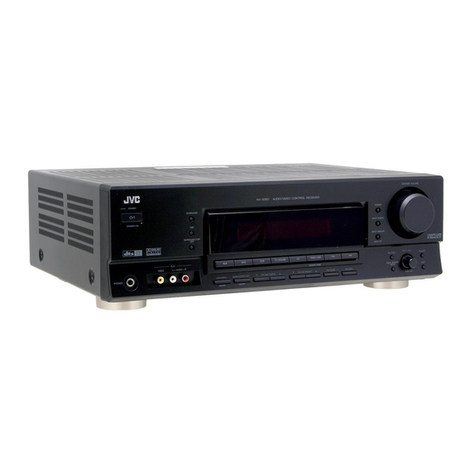
JVC RX-550VBK User manual

RX-550VBK
RX-550VLBK
JVC
RX-550VBK
move.
No.
RX-550VLBK
Feb.
1987

RX-550VBK
RX-550VLBK
Safety
Precautions
1.
The
design
of
this
product
contains
special
hardware
and
many
circuits
and
components
specially
for
safety
pur-
poses.
For
continued
protection,
no
changes
should
be
made
to
the
original
design
unless
authorized
in
writing
by
the
manufacturer.
Replacement
parts
must
be
identical
to
those
used
in
the
original
circuits.
Service
should
be
performed
by
qualified
personnel
only.
2.
Alterations
of
the
design
or
circuitry
of
the
product
should
not
be
made.
Any
design
alterations
or
additions
will
void
the
manufacturer’s
warranty
and
will
further
relieve
the
manufacturer
of
responsibility
for
persona!
injury
or
property
damage
resulting
therefrom.
3.
Many
electrical
and
mechanical
parts
in
the
product
have
special
safety-related
characteristics.
These
charac-
teristics
are
often
not
evident
from
visual
inspection
nor
can
the
protection
afforded
by
them
necessarily
be
ob-
tained
by
using
replacement
components
rated
for
higher
voltage,
wattage,
etc.
Replacement
parts
which
have
these
special
safety
characteristics
are
identified
in
the
Parts
List
of
the
Service
Manual.
Electrical
components
having
such
features
are
identified
by
shading
on
the
schematics
and
by
(
A
)
on
the
Parts
List
in
the
Service
Manual.
The
use
of
a
substitute
replacement
which
does
not
have
the
same
safety
characteristics
as
the
recom-
mended
replacement
part
shown
in
the
Parts
List
of
the
Service
Manual
may
create
shock,
fire,
or
other
hazards.
4.
The
leads
in
the
products
are
routed
and
dressed
with
ties,
clamps,
tubings,
barriers
and
the
like
to
be
sepa-
rated
from
live
parts,
high
temperature
parts,
moving
parts
and/or
sharp
edges
for
the
prevention
of
electric
shock
and
fire
hazard.
When
service
is
required,
the
original
lead
routing
and
dress
should
be
observed,
and
it
should
be
confirmed
the
they
have
been
returned
to
normal,
after
re-assembl-
5.
Leakage
current
check
(Electrical
shock
hazard
testing)
After
re-assembling
the
product,
always
perform
an
isolation
check
on
the
exposed
metal
parts
of
the
product
(antenna
terminals,
knobs,
metal
cabinet,
screw
heads,
headphone
jack,
control
shafts,
etc.)
to
be
sure
the
product
is
safe
to
operate
without
danger
of
electrical
shock.
Do
not
use
a
line
isolation
transformer
during
this
check.
¢
Plug
the
AC
line
cord
directly
into
the
AC
outlet.
Using
a
‘‘Leakage
Current
Tester’’,
measure
the
leakage
current
from
each
exposed
metal
part
of
the
cabinet,
particularly
any
exposed
metal
part
having
a
return
path
to
the
chassis,
to
a
known
good
earth
ground.
Any
leakage
current
must
not
exceed
0.5
mA
AC
(r.m.s.).
¢
Alternate
check
method.
Plug
the
AC
line
cord
directly
into
the
AC
outlet.
Use
an
AC
voltmeter
having
1,000
ohms
per
volt
or
more
sensitivity
in
the
following
manner.
Connect
a
1,500
2
10W
resistor
paralleled
by
a
0.15
uF
AC-type
Capacitor
between
an
exposed
metal
part
and
a
known
good
earth
ground.
Measure
the
AC
voltage
across
the
resistor
with
the
AC
voltmeter.
Move
the
resistor
connection
to
each
exposed
metal
part,
particularly
any
exposed
metal
part
having
a
return
path
to
the
chassis,
and
measure
the
AC
voltage
across
the
resistor.
Now,
reverse
the
plug
in
the
AC
outlet
and
repeat
each
measurement.
Any
voltage
measured
must
not
exceed
0.75
V
ACir.m.s.).
This
corresponds
to
0.5
mA
ACi(r.m.s.).
~
ing.
AC
VOLTMETER
(Having
1000
ohms/volt,
or
more
sensitivity.)
foe
!
0
18
xf
AC
TYPE
ie
Paes
I
:
Bi
Place
this
probe
ie
Dod
aw
+
.--1-e
on
each
exposed
L
1500
&
10
W
metal
part.
Good
earth
ground
-———_
|
|
|
———___——§——_+
CHECK
THE
VOLTAGE
SELECTOR’S
SETTING
(Except
for
U.S.A., Canada,
Australia,
U.K.
and
Continental
Europe)
'
Before
inserting
the
power
plug,
please
check
that
the
voltage
selector’s
setting
corresponds
with
this
equipment.
fs
voltage
selector
may
be
Jocated
on
the
rear
or
bottom
of
the
unit,
or
underneath
the
platter.
|
CAUTION
|
|
|
|
the
line
voltage
in
your
area.
If
it
doesn't
be
sure
to
reset
the
voltage
selector
before
operating
|
|
|
|
-
Before
setting
the
voltage
selector
to
the
proper
voltage,
disconnect
the
power
plug.
1-2
(No.2976)

f°
CYRADIT
Tf
IATIZ
WWII
US
AEN
fl!/Remote
[lil
Control
System
COMPU
LINK
REMOTE
CONTROL
SYSTEM
The
COMPU
LINK
REMOTE
CONTROL
SYSTEM
was
developed
by
JVC.
You
can
not
only
control
each
COMPU
LINK
component
from
the
remote
control
unit,
but
also
perform
the
following
advanced
operations
with
ease.
Automatic
source
selection
If
the
attached
remote
cable
is
used
to
connect
this
unit
to
other
JVC
components
with
COMPU
LINK-1/
SYNCHRO
terminals,
sources
can
be
switched
with
just
one
touch
of
this
unit's
source
selector
buttons
and
the
corresponding
component
wil!
start
to
play
automatically.
The
source
select
button
of
the
remote
control
unit
or
the
appropriate
component's
activation
button
may
also
be
used.
When
switching
over
from
one
component
to
another,
such
as
the
cassette
deck,
turntable
or
CD
player,
the
previous
component
will
stop
playing
after
about
five
seconds.
Synchronized
recording
Synchronized
recording
refers
to
the
process
whereby
the
cassette
deck
automatically
com-
mences
recording.
in
synchronization
with
the
CD
player
or
turntable
Set
the
cassette
deck
to
REC/PAUSE
mode
ac-
cording
to
the
procedures
in
the
instruction
manual
When
synchronously
recording
the
CD
player,
push
the
PLAY
button
on
the
CD
player.
The
cassette
deck
enters
the
record
mode
the
moment
the
CD
player
starts
and
synchronized
recording
commences.
Synchronized
recording
stops
automatically
when
the
CD
player
stops
playing.
To
cancel
synchronized
recording,
push
the
STOP
button
of
the
CD
player,
turntable
or
cassette
deck
Notes:
©
When
the
REC/PAUSE
mode
is
set
by
pushing
PAUSE
after
depressing
the
REC
and
PLAY
buttons
simultaneously,
synchronized
record-
ing
is
not
possible.
For
details,
refer
to
your
cassette
deck’s
instruction
manual.
¢
Abnormal
operation
will
result
if
the
power
supply
of
one
of
the
components
is
interrupted
during
synchronized
recording.
If
this
hap-
pens,
push
the
activation
button
again
to
restart.
¢
Ensure
that
the
COMPU
LINK-1/SYNCHRO
terminal
of
each
component
is
connected
with
the
attached
remote
cable.
Be
sure
to
read
the
instruction
manual
for
each
component
very
carefully.
©
The
source
is
locked
to
CD
or
PHONO
position
during
synchronized
recording
to
avoid
acci-
dental
stops
or
changing
to
another
source.
To
change
the
source,
first
cancel
the
synchron-
ized
recording.
RX-
RX-
COMPU
LINK-
FERNBEDIENSYSTEM
Das
COMPU
LINK-FERNBEDIENSYSTEM
ist
eine
JVC-Entwicklung.
Per
Fernbedienung
kénnen
nicht
nur
alle
COMPU
LINK-Komponenten
gesteuen,
sondern
auch
die
folgenden
Komfortfunktionen
geregelt
werden.
Automatische
Signalquellenwah!
Wenn
dieses
Gerat
mit
dem
mitgelieferten
Fern-
bedienkabel
an
andere,
mit
COMPU
LINK-1/
SYNCHRO-Buchsen
ausgestattete
JVC
Korrpo-
nenten
angeschlossen
wird,
kOnnen
diese
Kom-
ponenten
mit
nur
einem
Druck
der
erforderlichen
Signalquellentaste
an
diesem
Gerat
auf
Wieder-
gabestart
geschaltet
werden.
Signalquellentasten
an
der
Fernbedienung
und
die
entsprechende
Funk-
tionstaste
an
der
jeweiligen
Komponente
kdnnen
gleichfalls
verwendet
werden
Bei
Umschaltung
von
einer
Komponente
zur
anderen,
z.B.
Kassettendeck.
Plattenspieler
cder
CD-Player
stoppt
die
Wiedergabe
des
vorherigen
Gerats
nach
ca.
5
Sekunden
Synchro-Aufnahme
Synchro-Aufnahme
bedeutet
simultaner
automati-
scher
Aufnahmestart
des
Kassettendecks
bei
Wiedergabestart
von
Plattenspieler
oder
CD-Player.
Das
Kassettendeck
entsprechend
den
Angaben
in
der
Bedienungsanleitung
auf
Aufnahmnepause
schatten
Bei
Synchro-Aufnanme
vom
CD-Player
dessen
PLAY-Taste
betatigen.
Das
Kassettendeck
schaltet
bei
CD-Wieder-
gabestart
automatisch
auf
Aufnahme,
die
Synchro-
Aufnahme
startet.
Die
Synchro-Aufnahme
stoppt
automatisch
bei
Wiedergabeende
des
CD-Players.
Zur
Abschaltung
der
Synchro-Aufnahme
die
STOP-
Taste
von
CD-Player,
Plattenspieler
oder
Kassetign-
deck
etatigen
Hinweise:
Wenn
zur
Umschaltung
auf
Aufnahmepaise
die
PAUSE-Taste
nach
_
gleichzeitigem
Driicken
von
REC-
und
PLAY-Taste
betdigt
wird,
ist
keine
Synchro-Aufnahme
durchfihr-
bar.
Detaillierte
Angaben
hierzu
siehe
die
Bedienungsanleitung
des
Kassettendecks.
©
Wird
die
Spannungsversorgung
einer
Kompo-
nente
bei
Synchro-Aufnahme
unterbrochen,
treten
Betriebsstoérungen
auf.
In
diesem
fall
zum
emeuten
Start
die
Funktionstaste
betiti-
gen.
¢
Sicherstellen,
daB
die
COMPU
LINK-1/
SYNCHRO-Buchse
jeder
Komponente
tier
das
mitgelieferte
Fernbedienkabel
anges:h-
lossen
ist.
Die
Angaben
der
jeweiligen
Kan-
ponenten-Bedienungsanleitung
sorgfiiltig
beachten.
¢
Bei
Synchro-Aufnahme
ist
die
Signalquelle
in
Position
CD
oder
PHONO
arretiert,
um
1n-
beabsichtigte
Unterbrechungen
oder
Um-
schaltung
auf
andere
Signalquellen
zu
vr-
hindem.
Zur
Signalquellenumschaltuyg
zunachst
die
Synchro-Aufnahmetunkion
abschaiten.
550VBK
550VLBK
(No.2976)

RX-550VBK
RX-550VLBK
CONNECTION
DIAGRAM
ANSCHLUSSDIAGRAMM
DIAGRAMME
DES
RACCORDEMENTS
AANSLUITINGSSCHEMA
DIAGRAMA
DE
CONEXIONES
Open
the
speaker
terminal
with
the
lever
and
insert
the
stripped
end
of
the
cord
Die
Lautsprecherbuchse
mit
dem
Hebel
offnen,
und
das
abisolierte
Ende
des
Kabeis
einfuhren
Speakers
Ouvir
ia
borne
de
hautparleur
avec
le
levier
et
inserer
lextrémité
Lautsprecher
déundée
du
cable
de
haut-parleur
Enceintes
acoustiques
Open
de
luidsprekeraansiuiting
mb.v.
de
hendel
en
steek
het
|
Luidsprekers
blootliggende
uiteinde
van
het
luidsprekersnoer
in
de
aansluiting
Altavoces
Aora
el
terminal
del
aitavoz
con
fa
palanquila.
©
inserte
el
extreme
|
pelado
del
cordén
Clamp
the
wire
by
resetting
the
lever
Den
Draht
durch
Umlegen
des
Hebels
festkiemmen
Pincer
le
cable
en
replacant
le
levier
Bevestig
het
iuidsprekersnoer
door
de
hendel
terug
te
zetten
Fije
el
cable
soltando
ta
planquita
=
¢ g a $
"ACING
ey
UD
wena
m
10.09
@e
oor
oe
mb
lO
Ole
eaten
ts
oe
oyncnRo,
(O}}
ur
®
©
®
CATY
CONTROL
a
ee
Cassette
Deck
“Player
;
2
Cassettendeck
Turntable
Lecteur
de
disque
audionumeérique
Platine
a
cassette
Plattenspieler
Balch
diskspeler
f
Cassettedeck
Toume-disque
Tocadiscos
compacto
Magnetéfono
Draaitafel
Tocadiscos
ee
a
|
r----—-—---—
Speakers
Remote
cable
for
“COMPU
LINK"
Lautsprecher
Fernbedienkabel
fur
COMPU
LINK
Enceintes
acoustiques
Cable
de
télecommande
pour
"COMPU
LINK”
Fig.
1
Luidsprekers
Afstandsbedieningskabel
voor
“COMPU
LINK"
ans
1
Altavoces
Cable
de
mando
a
distancia
para
“COMPU
LINK”
Afb
4
External
ANTENNA
terminals
8
Antennenanschlusse
(ANTENNA)
GND
terminal
ErdungsanshluB
(GND)
CATV
CONTROL
terminal**
©
Gemeinschaftsantennen-SteuerungsanschluB
Connect
the
optional
CATV
antenna
control
unit.
(CATV
CONTROL)**
To
connect,
refer
to
the
instruction
book
of
the
Die
Gemeinschaftsantennen-Steuerungseinheit
CATV
antenna
contro!
unit
(Sonderzubehér)
anschlieBen.
Zum
AnschiieBen
siehe
die
Bedienungsanleitung
der
CATV-
Antennen-Steuerungseinheit
(No.2976)

RX-550VBK
RX-550VLBK
|
To
RF
cutout
An
BP
saan
Vers
sortie
HF
Naar
de
radiofre-
kwentie-uitgang
Hacia
la
salida
de
RF
VCR
Videorekorder
Magneéetoscope
Video-cassetterecorder
Grabador
de
video
cassette
To
TV
antenna
terminal
An
AntennenanschluB
Vers
la
borne
d'antenne
TY
Naar
de
televisie-antenneaansluiting
Hacia
el
terminal
de
antena
de
TV
AV
TV
To
TV
antenna
An
TV-Antenne
Vers
antenne
TV
Naar
de
televisie-antenne
Hacia
la
antena
de
TV
Video
disc
player
Bildplattenspieler
Lecteur
de
disque
vidéo
Video-diskspeler
Reproductor
de
videodisco
COAXIAL
(AUDIO)
Fg.
3
fob.
3
Ab.
3
(For
W.
Germany)
MIDED)
(Fur
Bundersrepublik
Deutschland)
Fig.
2
(Pour
l'Allemagne
de
l'Ouest)
Abb
2
(Voor
West-Duitsland)
Afb.
"9
(Para
Alemania
Occidental)
:
8
Bornes
d’antenne
externe
(ANTENNA)
C1)
Aansluitingen
voor
een
—
buitenantenne
Terminales
de
antena
externa
(AIT
ENNA)
Borne
de
mise
a
fa
terre
(GND)
(ANTENNA)
Terminal
de
puesta
a
tierra
(GND
®
Borne
de
contréle
CATV
(CATV
CONTROL)**
Aardaansluiting
(GND)
Terminal
de
control
CATV
(CATV
SONTROL)**
Raccorder
un
appareil
de
contrdle
d'antenne
CATV
CONTROL
aansluiting
(CATV
regeting)**
Conecte
la
unidad
de
control
deimtena
CATV
CATV
optionnel.
Pour
le
raccordement.
se
Sluit
de
los
verkrijgbare
CATV-antenne-
opcional.
Para
la
conexion,
refiérese
al
manual
référer
au
manuel
diinstructions
de
l'appareil
de
regeleenheid
aan.
Zie
de
gebruiksaanwijzingen
de
instrucciones
de
!a
unidad
e
control
de
contrle
d'antenne
CATV
van
de
CATV-antenneregeleenheid
voor
het
antena
CATV
aansluiten
‘
(No.2976)

RX-550VBK
RX-550VLBK
AC
QUTLET
SWITCHED
MAX
250W
AC
OUTLET
SWITCHED
MAX
250W
AC
OUTLET
SWITCHED
MAX
250W
TOTAL
MAX
150W.
For
Continental
Europe
Fur
Kontinental-Europa
Pour
Europe
Continentale
Voor
Europese
vasteland
Para
Europa
Continental
For
the
U.K.
Fiir
GroBbritannien
Pour
le
Royaume-Uni
Voor
Engeland
Para
R.U.
For
Australia
Fir
Australien
Pour
l’Australie
Voor
Australié
Para
Australia
For
the
U.S.A.,
Canada
and
other
areas
Fir
USA,
Kanada
und
andere
Gebiete
Pour
les
Estats-Unis,
le
Canada
at
les
autres
pays
Voor
de
V.S.,
Canada
en
andere
gebieden
Para
los
EE.UU.,
Canada
y
otros
paises
(No.2976)
Fig.
4
Abb.
4
Atb.
4
....For
audio
signal
connection
PHONO
terminals
CD
terminals
TAPE
1
REC
terminals
TAPE
1
PLAY
terminals
TAPE
2
REC
terminals
TAPE
2
PLAY
terminals
VCR
1
REC
terminals
VCR
1
PLAY
terminals
VCR
2
REC
terminals
B
VCR
2
PLAY
terminals
Note:
¢
These
VCR
1
and
VCR
2
terminals
can
also
be
used
to
receive
audio
signals
from
audio
equipment.
....For
video
signal
connection
@®
MONITOR
OUT
terminal
Connect
the
VIDEO
MONITOR
OUT
terminal
to
an
AV
TV
with
a
TV
OUTPUT
terminal
or
a
television
provided
with
a
video
input
terminal,
to
recproduce
video
signals.
@
VCR
1
REC
terminal
Connect
VCR
video
in
terminal
@
VCR
1
PLAY
terminal
Connect
any
of
several
JVC-specified
TVs,
an
AV TV
with
a
LINE
OUT
terminal
or
VCR
video
out
terminal.
@®
VCR
2
REC
terminal
@®
VCR
2
PLAY
terminal
)
AC
OUTLETS
(SWITCHED)
(Fig.
4)
)
Fuse
holder***
)
Voltage
selector****
When
this
equipment
is
used
in
an
area
where
the
supply
voltage
is
different
from
the
preset
voltage,
reset
the
voltage
selector
to
the
correct
position
SPEAKERS
1
terminals
SPEAKERS
2
terminals
Power
cord
....Fur
Audio-SignalanschiuB
Plattenspieler-Anschlusse
(PHONO)
CD-Spieler-Anschitisse
(CD)
Tonband-1-Aufnahmeanshlisse
(TAPE
1
REC)
Tonband-1-Wiedergabeanschllisse
(TAPE
1
PLAY)
©
Tonband-2-Autnahmeanschlisse
REC)
(9)
Tonband-2-Wiedergabeanschilisse
(TAPE
2
PLAY)
@
VCR
1
REC-Anschliisse
(VCR
1
REC)
g
VCR
1
PLAY-Anschluisse
(VCR
1
PLAY)
Videokassettenrekorder-Aufnahmeanschlisse
(VCR
2
REC)
®
Videokassettenrekorder-Wiedergabean
—
schlil-
sse
(VCR
2
PLAY)
Hinweis:
Diese
VCR
1-
und
VCR
2-Anschliisse
kénnen
auch
zum
Empfang
von
Audiosignalen
von
Audiogeriten
ver-
wendet
werden.
....
Fir
Videosignalverbindung
®
Monitorausgang
(MONITOR
OUT)
Ausgang
VIDEO
MONITOR
mit
der
Tv-
Ausgangsbuchse
eines
AV-TV-
Gerats,
bzw.
mit
dem
Videoeingang
eines
TV-Gerats
verbinden.
um
Videosignale
zu
zeigen.
@®
B8uchse
VCR
1
REC
An
VIDEO-Eingangsbuchse
des
recorders
anschlieBen.
@
Video
1-Buchsen
(VIDEO
1)
Mit
dem
Line-Ausgang
eines
JVC
TV-Gerdats
oder
AV-TV-Gerats
verbinden
oder
einem
Videogerat
mit
VIDEO
OUT-Buchse.
@®
Viceokassettenrekorder-AufnahmeanschluB
(VCR
2
REC)
@®
Viceokassettenrekorder-WiedergabeanschluB
(VCR
2
PLAY)
ALLGEMEIN
(D
Beschaltete
Netzausgaénge
(SWITCHED
AC
OUTLETS)
(Abb.
4)
Sicherunghalter***
Spannungswahler****
Wenn
die
zu
verwendende
Netzspannung
von
der
voreingesteliten
Betriebsspannung
dieses
Gerats
abweicht,
mit
dem
Spannungswahler
die
erforderliche
Spannung
einstellen
@®
|
autsprecher-1-Anschliisse
(SPEAKERS
1)
Lautsprecher-2-Anschliisse
(SPEAKERS
2)
Netzkabel
(TAPE
2
Video-
Example
Beispiel
Exemple
Voorbeeld
aT
CH.SPACING
>)
Raga
Switch
over
using
the
tip
of
a
ball-point
pen
as
shown
in
Fig.
5.
Verwenden
Sie
zum
Umschalten
die
Spitze
eines
Kugelschreibers,
wie
in
Abb.
5
gezeigt.
Changer
a
l'aide
d'un
stylo-bille
comme
indiqué
dans
la
Fig.
5.
Schakel
m.b.v.
een
balpen
over.
zoals
de
afbeelding
5
laat
zien.
Conmute
usando
la
punta
de
un
boligrafo
de
ja
[ouepete
que
se
ve
en
la
Fig.
5
@
AM
cahnnel
spacing
switch"**
The
AM
channel
spacing
switch
on
the
rear
panel
allows
selecticn
of
9
kHz
or
10
kHz
steps.
depending
on
your
area.
Area
(MW)
|
(LW)
U.S.A.,
Canada
100kHZz
|
10kHz
—
Continental
=
Band
=
|
AM
|
AM
50kKHz|
9kHz
|
1kHz
——_——_
Europe,
U.K.
Continental
Europe,
Australia
|
SCKHZ)
9kHz
|
—
9kHz*
Other
areas
50kHz
10kHz
_
Note:
*Preset
at
the
factroy.
AM
loop
antenna
COMPU
LINK-1/SYNCHRO
terminals
Connect
to
units
provided
with
a
COMPU
LINK-1
/SYNCHRO
terminal
to
let
the
COMPU
LINK
control
system
function
Notes:
1.
When
connecting
the
components,
make
the
correct
left
and
right
channel
connec-
tions.
Reversed
channels
may
degrade
the
stereo
effect.
2.
Connect
speakers
with
correct
polarity:
(+)
to
(+)
and
{-)
to
(-).
Reversed
polarity
may
degrade
the
stereo
effect.
3.
Switch
the
power
off
when
connecting
any
component.
4.
Connect
plugs
or
wires
firmly.
Poor
con-
tact
may
result
in
hum.
5.
Use
speakers
with
an
impedance
of
8
ohms
or
more
(16
ohms
when
the
1+
2
position
is
used).
Speakers
with
an
impe-
dance
down
to
4
ohms
(8
ohms
when
the
1
+
2
position
is
used)
may
be
used,
in
which
case
the
temperature
rise
of
the
cabinet
may
not
satisfy
BS
415
or
IEC
65.
Be
sure
to
provide
good
ventilation,
especially
when
speakers
with
an
impedance
of
4
ohms
(8
ohms
when
the
1
+
2
position
is
used)
are
used.
6.
The
AC
outlets
provide
no
power
when
the
power
is
turned
off.
Do
not
connect
equip-
ment
requiring
more
than
the
outlet’s
specified
value.
7.
Keep
the
connection
cords
as
far
as
possi-
ble
from
the
TV.
Provided
only
on
units
for
the
U.S.A.
and
Canada.
Not
provided
on
units
for
the
USA.
Canada,
the
U.K.,
and
Australia
Not
provided
on
units
for
the
USA..
Canada,
Continental
Europe.
the
U.K.,
and
Australia
wee
RX-550VBK
RX-550VLBK
@
MW-Kanalabstandtaste***
Mit
der
MW-Kanalabstandtaste
kann
ent-
sprechend
dem
Empfangsgebiet
der
kanal-
abstand
auf
9
kHz
oder
10
kHz
eingestelit
werden
\__Wellenbereich
ukw
|
Mw
|
Lw
Empfangsgebiet
USA.
Kanada
100kHz|10kKHz
|
—
Kontinenta!-Europa,
GroBbritannien
Kontinental-
SOKHz|
9kHz
|
1kHz
Europa.
Australien
|
S0KH2)
9kHz
|
—
9kHz*
[Andere
Gebiete
SOKHZ
|
6.145
Hinweis:
*Ab
Werk
voreingestellt.
@
Mw-Rahmenantenne
@
Synchro-Buchsen
(COMPU
LINK-1/
SYNCHRO)
Mit
dem
COMPU
LINK-1/SYNCHRO-Anschlu8
anderer
Komponenten
verbinden,
um
das
COMPU
LINK-Systerm
verwenden
zu
k6nnen
Hinweise:
1.
Beim
AnschlieBen
anderer
Gerite
auf
die
richtige
Zuordnung
des
finken
und
rechten
Kanals
achten.
Vertauschte
Kanale
vermindern
den
Stereoetiekt.
2.
Die
Lautsprecher
mit
richtiger
Polaritat
anschlieBen:
(+)
an
(+)
und
(-)
an
(-).
Vertauschte
Polaritat
kann
den
Stereoeffekt
vermindern.
3.
Vor
dem
AnschlieBen
anderer
Gerate
die
Spannungsversorgung
ausschalten.
4.
Die
Stecker
und
Kabel
fest
arschlieBen.
Schlechter
Kontakt
kann
zy
Stdérge-
rauschen
ftihren.
5.
Lautsprecher
mit
einer
Impedanz
von
8
Ohm
oder
mehr
verwenden
(16
Ohm,
wenn
die
Position
1
+
2
verwendet
wird).
Lautsprecher
mit
einer
Impedanz_
bis
hinunter
zu
4
Ohm
(8
Ohm,
wem
die
Posi-
tion
1
+
2
verwendet
wird)
kémnen
ver-
wendet
werden,
dann
entspricht
der
Temperaturanstieg
des
Gehduses
even-
tuell
nicht
der
BS
415
oder
IEC
5.
Fiir
eine
gute
Beliiftung
sorgen,
vor
alem
wenn
Lautsprecher
mit
einer
Impecanmz
von
4
Ohm
(8
Ohm,
wenn
die
Posiion
1
+
2
verwendet
wird)
verwendet
ween.
6.
Bei
abgeschalteter
Spannunysversorg-
ung
sind
die
Netzausginge
ebenfalls
abgeschaltet.
Keine
Gerdte
arschlieBen,
die
die
Ausgangsnennleistung
dibersch-
reiten.
7.
Die
Anschlu8kabel
so
weit
we
médglich
vom
Fernseher
entfemt
verlegen.
Vorhanden
nur
bel
Geraten
fir
die
USA
und
Kanada.
Nicht
vorhanden
bei
Geraten
‘ir
die
USA,
Kanada,
Gro8britannien
und
/ustralien
Nicht
vorhanden
bei
Geraten
‘ir
die
USA,
Kanada,
_
Kontinental-Eurog.
GroB-
britannien
und
Australien
(No.2976)

RX-550VBK
RX-550VLBK
ANTENNAS
ANTENNEN
ANTENNES
Use
of
CATV
cable
Verwendung
des
Kabel-TV-Kabels
Utilisation
d'un
cable
CATV
Gebuik
van
de
CATV-Kabel
Uso
del
cable
CATV
FM
extérnal
antena
ANTENNES
ANTENAS
Used
along
with
CATV
antenna
contro!
unit
(Refer
to
the
instruction
book
of
CATV
antenna
control
unit)
Verwendung
mit
einer
Kabel-TV-Antennensteuereinheit
(Siehe
Bedienungsanleitung
der
Antennensteuereinheit)
Utilisées
avec
un
boitier
de
commande
d’antenne
CATV
(Se
reporter
au
manuel
d'instructions
du
boitier
de
commande
d'antenne
CATV)
Wordt
samen
met
een
CATV-antenneregeleenheid
gebruikt
UKW-AuBenantenne
Antenne
externe
FM
FM-buitenantenne
Antena
exterior
de
FM
CATV
cable
Kabel-TV-Kabel
Cable
catv
catv-kabel
Cable
CATV
(Zie
tevens
de
gebruiksaanwijzing
van
de
CATV-antenneregeleen-
heid)
Se
utilizan
junto
con
la
unidad
de
control
de
antena
CATV
(Refiérase
al
manual
de
instrucciones
de
la
unidad
de
control
de
antena
CATV)
To
AV
antenna
terminal
An
AV-Antenenanshlu8
Vers
borne
d’antenne
AV
Naar
de
AV-antenneaansluiting
Hacia
el
terminal
de
antena
AV
Fig.
8
Abb.
8
Afb.
8
Fig.
10
Abb.
10
Afb.
10
(No.2976)
+
64
ATVOUT
CATVIN
ExT
Pun
AM
antennas
(Fig.
8,
9)
©
How
to
assemble
the
AM
foop
antenna
(Fig.
8)
Snap
the
ioop
antenna
onto
the
stand,
then
slide
it
as
shown
until
firmly
held
in
place.
®
When
too
much
noise
occurs
(Fig.
9)
Change
the
direction
of
the
loop
antenna
or
rein-
stall
it
in
a
position
that
gives
best
reception.
@
AM
externa!
antenna
(Fig.
10)
if
AM
reception
is
not
good,
connect
an
external
AM
antenna
(single-wire
antenna)
to
the
AM-
ANTENNA
terminal.
Notes:
©
If
the
provided
loop
antenna
is
not
set
up
and
its
wires
attached,
or
the
antenna
wires
touch
the
rear
panel,
it
will
be
impossible
to
receive
AM
broadcasts.
©
When
installing
an
AM
external
antenna,
leave
the
AM
loop
antenna
connected.
*lf
the
AM
loop
antenna
is
too
close
to
the
speaker
terminals,
it
may
cause
noise
and
should
be
moved
away
from
the
rear
panel.
FM
antennas
@75-ohm
antenna
with
coaxial
lead
(Fig.
11)
Loosen
the
screws
on
the
bracket
and
insert
the
cable
into
the
ring
from
below.
Then
connect
the
stripped
core
to
the
upper
terminal.
The
bracket
ring
works
as
the
ground
terminal.
©
Feed
antenna
(Fig.
12)
Connect
to
the
300-ohm
terminal
Take
care
that
the
wires
of
the
feeder
antenna
do
not
touch
any
other
terminal
For
W.
Germany
(Fig.
13)
e
The
FM
wire
antenna
provided
can
be
connected
to
the
75-ohm
coaxial
jack
temporarily.
@
75-ohm
antenna
with
coaxial
type
connector
(DIN
45
332)
Connect
to
the
75-ohm
terminal.
F-type
converter
plug
(attached
to
CATV
antenna
control
unit)
When
using
the
FM
antenna,
attach
to
this
apparatus.
F-Steckeradapter
(zur
steuereinheit
befestigt)
¢Fur
UKW-Antenne
diesen
Adapter
ver-
wenden
Fiche
de
conversion
type
F
(fixée
au
boitier
de
commande
d'antenne
CATV)
En
utilisant
!'antenna
FM’
fixer
A
cet
appareil.
F-type
konversiestekker
(bevestigd
aan
de
CATV-antenneregeleenheid.)
©
Op
dit
apparaat
aansluiten
wanneer
de
FM-
antenne
gebruikt
wordt.
Clavija
convertidora
tipo
F
(fijada
a
la
unidad
da
control
de
antena
CATV)
¢
Cuando
utilice
la
antena
de
FM,
fijela
a
esta
aparato.
Kabel-TV-Antennen-
Using-F-type
connector
Verwendung
eines
F-Anschlusses
Utilisant
un
connecteur
de
type
F
Bij
gebruik
van
de
F-type
aansluiting
Uso
del
conector
tipo
F
AM-Antennen
(Abb.
8,
9)
@
Anbringung
der
AM-Rahmenantenne
(Abb.
8)
Die
Rahmenantenne
am
Halter
festdrucken
und
dann
wie
gezeigt
verschieben,
um
sicheren
Sitz
zu
gewahrleisten
@
Wenn
zu
viele
Stogerausche
empfangen
werden
(Abb.
9)
-
Die
Richtung
der
Rahmenantenne
verandern
oder
in
einer
Position
anbringen,
die
einen
besseren
Empfang
ergibt
¢
MW-AuBenantenne
(Abb.
10)
Wenn
der
MW-Empfang
nicht
gut
ist,
eine
MW-
AuBenantenne
(Einzeldrahtantenne)
an
den
AM
ANTENNA-Anschlu8
anschlieBen
Hinweise:
©
Wenn
die
mitgelieferte
Rahamenantenne
nicht
angebracht
und
angeschlossen
ist
oder
die
Antennendrahte
die
Riickplatte
beriihren,
ist
MW-Empfang
nicht
méglich.
*
Die
MW-Rahmenantenne
muB
auch
angesch-
lossen
bleiben,
wenn
eine
MW-AuBenantenne
angeschlossen
wird.
©
Wenn
die
MW-Rahmenantenne
sich
zu
nahe
an
den
Lautsprecheranschliissen
befindet,
kSnnen
Stdrgerausche
auftreten.
Daher
die
Rahmenantenne
mdglichst
weit
von
der
Riick-
platte
entfemt
anbringen.
UKW-Antennen
@
75-Ohm-Antenne
mit
Koaxialkabel
(Abb.
11)
Die
Schrauben
an
der
Halterung
ldsen
und
das
Kabel
von
unten
in
den
Ring
einfiihren
Dann
den
abisolierten
Innenleiter
an
die
obere
Klemme
anschieBen.
Der
Halterungsring
dient
als
Erdungsklemme.
®
Speiseantenne
(Abb.
12)
An
die
300-Ohm-Klemme
anschlieBen
Darauf
achten.
daB
die
Kabel
der
Speiseantenne
die
anderen
Anschlusse
nicht
berihren.
Fiir
BRD
(Abb.
13)
®
Die
mitgelieferte
UKW-Drahtantenne
kann
zeit-
weilig
an
die
75-Ohm-Koaxialbuchse
angesch-
lossen
werden.
¢
75-Ohm-Antenne
mit
Koaxialstecker
(DIN
45
332)
An
den
75-Ohm-Anschlu8
anschlieBen.

When
using
2
FM
antennes
Verwendung
von
2
UKW-Antennen
Utilisation
de
2
antennes
FM
Bij
gebruik
van
2
FM-antenne’s
Cuando
utilice
2
antennas
de
FM
@
CATV
antenna
control
unit
can
also
be
used
as
a
switching
unit
for
2
FM
antennas.
¢
Die
Kabel-TV-Antennensteuereinheit
kann
kann auch
als
Umschalter
fur
2
UKW-Antennen
verwendet
werden.
e
Le
boitier
de
commande
d'antenne
CATV
peut
aussi
étre
utilisé
comme
un
commuteur
pour
2
antennes
FM.
De
CATV-antenneregeleenheid
kan
ook
gebruikt
worden
als
een
schakeleenhied
tussen
twee
FM-
antenne’s.
e
También
puede
utilizarse
la
unidad
de
control
de
antena
CATV
como
unidad
de
conmutacién
para
2
antenas
de
FM.
Fig.
7
Abb.
7
Afb.
7
Antennes
AM
(Fig.
8,
9)
©
Montage
de
l'antenne
a
boucle
AM
(Fig.
8)
Dresser
l'antenne
a
boucle
sur
te
support,
puis
la
glisser
comme
montré
jusqu’a
ce
qu'elle
tienne
bien
en
place.
®
Si
trop
de
bruit
est
produit
(Fig.
9)
Changer
la
direction
de
l'antenne
a
boucle
ou
ta
réinstaller
dans
une
position
ou
la
réception
est
meilleure.
@
Antenne
AM
externe
(Fig.
10)
Si
la
réception
AM
n'est
pas
bonne,
raccorder
une
antenne
AM
externe
(angenne
a
fil
simple)
a
la
borne
AM
ANTENNA.
Remarques:
©
Si
'antenne
a
boucle
fournie
n'est
pas
en
place
et
que
ses
fils
sont
fixés
ou
que
les
fils
d'antenne
touchent
le
panneau
arriére,
if
sera
impossible
de
recevoir
les
émissions
AM.
eLors
de
[installation
dune
antenne
AM
externe,
laisser
'antenne
4
boucle
AM
raccor-
dée.
©
Si
l'antenne
a
boucle
AM
est
trop
prés
des
bornes
de
haut-parleurs,
il
y
a
risque
de
bruit
et
elle
doit
étre
éloignée
du
panneau
arriére.
Antennes
FM
@
Antenne
de
75
ohms
avec
conducteur
co-axial
(Fig.
11)
Desserrer
les
vis
sur
le
collier
et
insérer
le
cable
dans
ia
bague
depuis
le
dessous.
Raccorder
en-
suite
le
fil
dénudé
sur
la
borne
supérieure.
La
bague
du
collier
sert
de
borne
de
mise
a
la
terre.
@
Antenne
a
cable
plat
(Fig.
12)
La
raccorder
a
la
borne
de
300
ohms.
Attention
a
ce
que
les
fils
de
l'antenne
a
cable.
Pour
Pallemagne
de
l'Ouest
(Fig.
13)
@
(’antenne
a
cable
FM
fournie
peut
étre
raccordée
temporairement
a
la
prise
co-axiale
de 75
ohms.
¢
Antenne
de
75
ohms
avec
prise
de
type
co-axial
(DIN
45
332)
La
raccorder
a
la
borne
de 75
ohms.
AM-antenne’s
(Afb.
8,
9)
@
Monteren
van
de
AM-raamantenne
(Afb.
8)
Klik
de
raamantenne
op
de
standaard
en
schuif
hem
daarna
zoals
dit
wordt
aangegeven,
totdat
de
antenne
stevig
op
zij
plaats
vastgehouden
wordt.
@
Wanneer
overmatige
storing
optreedt
(Afb.
9)
De
antenne
bijstellen
of
verplaatsen
naar
een
posi-
tie
waar
ontvangst
het
best
is.
@
Am-buitenantenne
(Afb.
10)
Sluit
een
AM-buitenantenne
—
(enkeldraads-
antenne)
aan
op
de
AM
ANTENNA
aansluiting
wanneer
de
AM-ontvangst
niet
voldoende
is.
Opmerkingen:
Het
is
onmogelijk
AM-uitzendingen
to
ont-
vangen,
wanneer
de_
bijgeleverde
AM-
raamantenne
niet
aangesloten
en
opgesteld
is
of
wanneer
de
antennedraden
het
achter-
paneel
aanraken.
©
Laat
tevens
de
AM-raamantenne
aangesloten
bij
aansluiting
van
een
AM-buitenantenne.
e
Als
de
AM-raamantenne
zich
te
dicht
bij
de
luidsprekeraansluitingen
bevindt,
kan
deze
tuis
veroorzaken
en
dient
dan
uit
de
buurt
van
het
achterpaneel
gepiaatst
te
worden.
FM-antenne’s
@
75
Ohm
antenne
met
coaxiale
draad
(Afb.
11)
Draao
de
schroeven
op
de
beugel
los
en
steek
de
kabel
van
onderen
in
de
ring.
Verbind
dan
de
ont-
blootte
kerndraad
met
de
bovenste
aansluiting.
De
beugelring
funktioneert
als
aardaansluiting.
@
Voedingsantenne
(Afb.
12)
Sluit
deze
aan
op
de
300
Ohm
aansluiting.
Zorg
ervoor
dat
de
draden
van
de
voedings-
antenne
de
andere
aansluiting
niet
aanraakt.
Voor
Westduitsland
(Afb.
13)
De
meegeleverde
FM-draadantenne
kan
tijdelijk
aangesloten
worden
op de
koaxiale
aansluiting
van
75
Ohm.
@
FM-antenne
van
75
Ohm
met
koaxiale
aansluiting
(DIN
45332)
Aansluiten
op
de
75
Ohm
aansluiting
RX-550VBK
RX-550VLBK
10.
$3]
10
|{in
mm)
Fig.
11
Abb.
11
Afb.
11
|
Fig.
12
Abb.
12
Atb.
12
Antenas
de
AM
(Fig.
8
y
9)
®
Como
montar
la
antena
de
cuadro
de
AM
(Fig.
8)
Coloque
la
antena
en
el
soporte
y
deslicela
como
se
ilustra
hasta
que
quede
firmemene
fijada
en
su
lugar.
®
Cuando
hay
demasiado
ruido
(Fig.
9)
Cambie
la
direccién
de
fa
antera
o
instalela
nuevamente
en
una
posicidn
que
pemita
ja
mejor
recepcion
®
Antena
externa
AM
(Fig.
10)
Si
la
recepcién
de
AM
no
es
buena,
conecte
una
antena
externa
de
AM
(antena
maofilar)
al
ter-
minal
AM
ANTENA.
Notas:
*Si
la
antena
de
cuandro
provita
no
esta
instalada
o
los
cables
de
la
misna
tocan
el
panel
trasero,
sera
imposble
captar
radiodifusiones
en
AM.
Cuando
instale
una
antena
eiterna,
deje
conectada
la
antena
de
cuadro
@
AM.
°
Si
la
antena
de
cuadro
AM
esté
cemasiada
cerca
a
los
terminales
del
altwoz,
puede
producirse
ruido-y
se
la
debera
alearr
del
panel
trasero.
Antenas
FM
¢
Antena
de
75
ohmios
con
cable
caxil
(Fig.
11)
Afloje
los
tornillos
en
la
ménsula
e
inerte
el
cable
en
el
aro
desde
abajo.
Luego
conece
el
extremo
pelado
al
terminal
superior.
El
aro
@
la
ménsula
trabaja
como
terminal
de
conexidn:
tierra
e
Alimentador
de
antena
(Fig.
12)
Conecte
al
terminal
de
300
ohmios,
Tenga
cuidado
de
que
los
aambres
del
alimentador
de
antena
no
toquen
mingtin
otro
terminal.
Para
Alemania
Occidental
(Fig.
13)
ela
antena
de
cable
suministada
puede
conectarse
temporariamente
al
terr-al
coaxil
de
75
ohmios.
e
Antena
de 75
ohmios
con
conectr
tipo
coaxil
(DIN
45
332)
Connecte
al
terminal
de
75
ohmios
(No.2976)

RX-550VBK
RX-550VLBK
FRONT
PANEL
FRONTPLATTE
PANNEAU
AVANT
VOORPANEEL
PANEL
DELANTERO
Ce
RS
SS
Fe
ee
ee
ee
a
SEA
GRAPHIC
EQUALIZER
-———1u
SEA
PRESET
fi
MANUAL
0:
anes
JB
GSH
(No.2976)
@
POWER
ON:
Press
to
turn
the
power
on.
To
turn
the
power
off,
press
it
again.
Even
when
the
power
is
turned
off,
the
STAND
BY
indicator
remains
lit
unless
the
receiver
is
unplugged
from
the
wall
outlet.
STAND
BY:
Even
when
all
the
indicators
other
than
the
STAND
BY
indicator
are
turned
off,
the
memory
circuit
operates
and
the
preset
stations
and
the
source
selectors
are
not
subject
to
cancellation
or
accidental
alteration
as
long
as
the
power
cord
is
plugged
into
the
wall
outlet
This
situation
is
called
the
STAND
BY
mode.
The
preset
data
and
the
source
select
data
are
main-
tained
even
in
the
case
of
a
power
faliure
or
while
the
power
is
not
applied
with
the
power
cord
disconnected
from
the
wall
outlet
for
a
couple
of
days.
Note:
¢
Even
in
the
STAND
BY
mode,
this
receiver
consumes
a
small
amount
of
electricity
(5
watts).
To
shut
the
power
completely
off,
disconnect
the
power
cord.
WOHZ
400HZ
tkHz
@
Netztaste
(POWER)
ON:
Netzspannung
mit
dieser
Taste
einschalten
Zum
Ausschalten
erneut
driicken.
Auch
bei
ausgeschalteter
Netzspannung
leuchtet
die
STAND-BY-Anzeige
weiterhin
auf,
solange
das
Netzkabel
des
Receivers
nicht
von
der
Wand-
steckdose
abgezogen
ist.
STAND
BY:
Auch
wenn
auBer
der
STAND-BY-
Anzeige
keine
der
Anzeigen
aufleuchtet,
ist
der
Speicherschaltkreis
in
Betrieb,
und
die
Vorwahl-
stationen
und
Programmauellen
werden
vom
Abschalten
oder
unbeabsiohtigter
Anderung
nicht
beruhrt,
solange
das
Netzkabel
an
die
Wandsteckdose
angeschlossen
ist.
Dieser
Betriebszustand
heiBt
STAND
BY.
Die
vor-
eingestelltén
Daten
und
Programmquellen
bleiben
also
auch
bei
Stromausfall
erhalten
und
gleichermaBen,
wenn
das
Netzkabel
einige
Tage
lang
von
der
Wandsteckdose
abgezogen
ist.
Hinweis:
°
Auch
bei
STAND
BY-Betriebsart
wird
eine
geringe
Leistung
(5
Watt)
vom
Receiver
aufgenommen.
Zur
kompletten
Abschalt-
ung
das
Netzkabel
abziehen.

RX-550VBK
RX-550VLBK
'
4
ACOUSTIC
ONITOR
|
EXPANDER
COMPUTER
Note:
@
STAND
BY
Indicator
Connecting
the
power
plug
to
the
AC
wall
outlet
causes
this
indicator
to
light,
indicating
that
the
unit
has
been
placed
in
the
stand-by
mode.
Hinweis:
¢
STAND
BY
Anzeigeleuchte
Wenn
man
das
Netzkabel
an
die
Wandsteckdose
anschlieBt,
leuchtet
diese
Anzeige
auf,
und
das
Gerit
ist
betriebsbereit.
Remarque:
*
Témoin
STAND
BY
Le
fait
de
brancher
la
fiche
d’alimentation
a
une
prise
secteur
entraine
Vallumage
de
ce
témoin,
signifiant
que
l'appareil
est
passé
en
mode
attente.
Opmerking:
e
Ruststandindikator
(STAND
BY)
Zodra
de
stekker
van
het
netsnoer
in
het
stopkontakt
wordt
gestoken,
zal
deze
indikator
oplichten
om
aan
te
geven
dat
het
apparaat
in
de
“standby”
stand
staat.
Nota:
©
Indicador
de
modo
de
espera
(STANDBY)
Cuando
se
conecta
el
enchufe
del
cable
de
alimentacon
al
toma-
corriente
mural
de
CA,
este
indicador
se
iluminara
indicando
que
la.
unidad
se
encuentra
en
el
modo
de
espera
(STANDBY).
Afb.
14
@
Alimentation
(POWER)
@
Spanning
toets
(POWER)
@
POWER
ON:
Appuyer
sur
la
touche
pour
mettre
l'appareil
sous
tension.
Pour
couper!'alimentation,
appuyer
de
nouveau
sur
la
touche.
Méme
sil'alimentation
est
coupée,
le
temoin
STAND
BY
reste
allumé
sauf
si
le
récepteur
est
débranche
de
la
prise
secteur.
STAND
BY:
Méme
quand
tous
les
temoins
autres
que
le
teémoin
STAND
BY
sont
éteints.
le
circuit
de
mémoire
fonctionne
et
les
stations
préreglées
et
les
sélecteurs
de
source
ne
sont
pas
soumis
a
une
annulation
ou
altération
tant
que
le
cordon
d'alimentation
est
branché
a
la
prise
secteur.
Cette
situation
est
appelée
mode
STAND
BY
(attente).
En
cas
de
coupure
acci-
dentelle
d'alimentation
ou
lorsque
lalimentation
est
coupée
avec
le
cordon
débranché
de
la
prise
secteur,
les
données
préréglées
et
les
données
de
sélection
de
source
sont
protégées
pendant
deux
jours
Remarque:
©
Méme
dans
le
mode
STAND
BY,
cet
ampli-
syntoniseur
consomme
une
faible
quantité
d'électricité
(5
watts).
Pour
couper
com-
pletement
f'alimentation,
débrancher
le
cordon
secteur.
ON:
Druk
op
deze
toets
om
het
apparaat
in
te
schakelen.
Druk
nogmaals
op de
toets
om
het
apparaat
weer
uit
te
schakelen.
Na
het
uitscha-
kelen
van
het
apparaat
zal
de
ruststandindikator
(STAND
BY)
blijver
oplichten.
tenzij
de
stekker
van
het
netsnoer
it
het
stopkontakt
wordt
getrokken.
STAND
BY:
Als
de
ruststandindikator
(STAND
BY)
oplicht
maar
alle
andere
indikators
uit
zijn.
betekent
dit
dat
het
geheugencircuit
in
bedrijf
is
en
de
voorkeuzestations
en
instellingen
van
de
bronselektors
niet
gewist
of
veranderd
zullen
worden.
zolang
het
netsnoer
tenminste
op
een
stopkontakt
aangesloten
is.
Deze
toestand
wordt
de
ruststand
(STAND
BY)
genoemd.
De
in
het
geheugen
opgesilagen
gegevens
betreffende
de
stations
en
de
gekozen
geluidsbron
blijven
ook
bewaard
als
er
een
stroomonderbreking
mocht
ziin
of
de
stekker
uit
het
stopkontakt
wordt
getrokken,
mits
dit
niet
langer
dan
een
paar
dagen
duurt
Opmerking:
¢
Zelfs
wanneer
de
STAND
BY-funktie
van
dit
toestel
ingeschakeld
is,
verbruikt
deze
versterker
een
kleine
hoeveelheid
stroom
(5
Watt).
Haal
de
stekker
uit
het
stopkontakt
om
de
spanning
volledig
uit
te
schakelen.
ON:
Presidnelo
para
conectar
laalimentacion.
Para
desconectar
la
alimentacia,
presionelo
nuevamente.
Aun
cuando
se
cesconecte
la
alimentacion,
el
indicador
de
mcio
de
espera
(STANDBY)
permanece
tluminadca
menos
que
se
desenchufe
el
receptor
del
ornacorriente
mural
STAND
BY:
Aun
cuando
todos
Ic
indicadores,
excepto
el
indicador
de
mod
de
espera
(STANDBY)
estén
apagados,
el
sircuito
de
la
memoria
funciona
y
las
estacions
y
los
selec-
tores
de
fuente
preajustados
no
esa
n
expuestos
a
ser
borrados
o
alterados
acicientalmente
mientras
que
el
cable
de
alimenacion
perma-
nezca
enchufado
al
tomacorriere
mural.
Esta
condicion
se
denomina
mod:
de
espera
(STANDBY).
Los
datos
preajustaoss
y
los
datos
de
seleccién
de
fuente
no
se
beraan
aun
en
el
caso
en
que
ocurra
un
corte
elécrico
0
Cuando
la
alimentacion
no
esté
conectad:
ees
decir,
con
el
cable
de
alimentacién
desacchufado
del
tomacorriente
mural,
por
un
pare
dias.
Nota:
e
Aun
en
el
modo
STAND
BY
esste
receptor
consume
una
pequena
:asntidad
de
electricidad
(5
vatios).
Dseenchufe
el
cordén
de
alimentacién
par
cSesconectar
completamente
la
alimentac
irw.
(No.2976)

RX-550VBK
RX-550VLBK
(No.2976)
@
SEA
GRAPHIC
EQUALIZER
indicator
The
dot
point
rises
and
falls
in
response
to
the
pressing
of
the
corresponding
SEA
LEVEL
buttons
to
show
the
SEA
level
in
each
frequency
band.
@
SEA
PRESET
pattern
indicator
Pressing
the
MANUAL/PROGRAMED
button
will
cause
indicator
A.
B.
C.
D.
or
E
to
fight.
according
to
which
preset
pattern
was
being
used
the
last
time
the
unit
was
in
that
particular
mode
(MANUAL
or
PROGRAMED).
If
no
preset
pattern
was
being
used.
no
preset
pattern
indicator
will
light.
These
indicators
also
light
when
an
SEA
PRESET
button
has
been
pressed,
to
select
a
preset
pattern
or
to
store
a
newly-
created
pattern
in
memory.
©
MANUAL/PROGRAMED
indicator
Pressing
the
MANUAL/PROGRAMED
button
causes
“MANUAL”
or
“"PROGRAMED"
to
light
on
the
display,
indicating
which
mode
has
been
selected.
@
MEMORY
indicator
Pressing
the
MEMORY
button
—
lights
“MEMORY”
for
about
five
seconds,
thus
indicating
the
unit
is
ready
to
store
in
memory
the
pattern
you
have
created.
@
SOUND
indicator
This
shows
which
audio
signal
has
been
selected
with
the
source
selectors.
for
listening
to
or
recording.
@
VISUAL
indicator,
This
shows
which
video
signal
has
been
selected
with
the
VIDEO
source
selectors,
for
watching
or
recording
@
LOUDNESS
indicator
When
the
LOUDNESS
button
has
been
pressed,
this
indicator
lights.
@
MUTE
indicator
This
indicator
lights
when
the
MUTE
button
has
been
pressed.
Press
it
again
returns
the
volume
to
its
original
level.
Pressing
the
VOLUME
UP/DOWN
buttons
also
cancels
the
muting.
@
SEA-Mehrbereichsklangregler-Pegelan-
zeige
(SEA
GRAPHIC
EQUALIZER)
Durch
Drucken
der
SEA-LEVEL-Taste
bewegt
sich
der
entsprechende
Punkt
aufwarts
oder
abwarts
und
zeigt
dadurch
den
SEA-Pegel
im
jewelligen
Frequenzbereich
an.
©
SEA-Vorwahimuster-Anzeige
(SEA
PRESET)
Wenn
die
©
MANUAL/PROGRAMED-Taste
gedruckt
wird,
leuchtet
die
Anzeige
A,
B,
C,
D
oder
E
entsprechend
dem
Vorwahimuster,
das
verwendet
wurde,
als
sich
das
Gerat
das
letzte
Mal
in
dieser
bestimmten
Betriebsart
(MANUAL
oder
PROGRAMED)
befand.
Wurde
kein
Vorwahimuster
verwendet,
leuchtet
auch
keine
Vorwahlmuster-Anzeige.
Diese
Anzeigen
leu-
chten
auch
nach
Drucken
einer
SEA
PRESET-
Taste
zum
Wahlen
eines
Vorwahimusters
oder
zum
Speichern
eines
neu
eingesteliten
Vorwahlmusters.
©
Manuell/Programm-Anzeige
(MANUAL/PROGRAMED)
Wenn
die
MANUAL/PROGRAMED-
Taste
gedruckt
wird.
leuchtet
“MANUAL”
oder
“"PROGRAMED"
auf
dem
Display.
wodurch
die
gewahlte
Betriebsart
angezeigt
wird.
@
Speicher-Anzeige
(MEMORY)
Wenn
die
MEMORY-Taste
gedriickt
wird,
leuchtet
“MEMORY”
fir
etwa
funf
Sekunden.
Wahrend
dieser
Zeit
kann
das
_
eingesteilte
Muster
gespeichert
werden.
@
Klang-Anzeige
(SOUND)
Diese
Anzeige
zeigt.
welches
Audiosignal
mit
den
Signalquellenwahlern
fur
Wiedergabe
oder
Aufnahme
gewahlt
wurde.
@
Visuell-Anzeige
(VISUAL)
Diese
Anzeige
zeigt,
welches
Videosignal
mit
den
VIDEO-Signalquellenwahlern
fiir
Wieder-
gabe
oder
Aufnahme
gewahlt
wurde.
©
Lautstdrkekontur-Anzeige
(LOUDNESS)
Diese
Anzeige
leuchtet,
wenn
die
LOUDNESS-
Taste
gedriickt
wurde.
©
Déamptungsanzeige
(MUTE)
Diese
Anzeige
leuchtet
nach
Betatigen
der
MUTE-Taste.
Durch
nochmaliges
Betatigen
wird
wieder
auf
die
urspriingliche
Lautstarke
geschaltet,
ebenfalls
durch
Betatigen
der
VOLUME
UP/DOWN-Taste.

@
VOLUME/BALANCE/SLEEP
TIMER
(x
10
MIN)
indicator
This
indicator
is
used
as
the
VOLUME,
BALANCE,
or
SLEEP
TIMER
indicator.
Normally,
“VOLUME”
lights
and
this
indicator
shows
the
level
of
sound
going
to
the
speakers
or
headphones.
When
the
BALANCE
buttons
are
pressed,
“BALANCE”,
the
center
bar,
“L”
and
“R’
light
and
the
balance
between
the
right
and
left
speakers
is
shown.
When
the
SLEEP
button
on
the
remote
control
unit
is
pressed,
“SLEEP
TIMER
(x
10
MIN)"
lights.
Each
time
the
SLEEP
button
is
pressed,
the
sleep
timer’s
setting
is
increased
in
10-minute
increments
to
up
to
60
minutes,
with
a
square
on
this
indicator
lighting
for
each
10-minute
increment
added.
However,
the
leftmost
point
does
not
light
in
this
mode.
This
indicator
is
also
useful
to
check
the
timer’s
turn-off
time.
The
display
continues
in
the
BALANCE
or
SLEEP
TIMER
indication
mode
for
about
five
seconds,
and
then
returns
to
the
VOLUME
indication
mode.
@
TAPE-2
MONITOR
indicator
When
the
TAPE-2
button
has
been
pressed,
this
indicator
lights.
@
ACOUSTIC
EXPANDER
indicator
This
indicator
lights
when
the
ACOUSTIC
EXPANDER
button
has
been
pressed
to
ON.
@
COMPUTER
SEA
indicator
When
the
SEA
SOURCE
button
is
pressed,
lights
to
show
that
the
S.EA.
is
processing
the
signals
fed
to
the
speakers
or
headphones.
When
the
SEA
REC
button
is
pressed,
the
lights
to
show
that
the
S.EA.
is
processing
the
signals
output
from
the
REC
OUT
terminals.
@
FM/AM
indicator
“FM”
is
displayed
during
FM
reception
and
"AM"
during
AM
reception.
@
Frequency
indicator
The
tuned-in
frequency
is
displayed
digitally.
Four
digits
(KHz)
are
displayed
during
AM
reception,
five
digits
(MHz)
(for
Europe,
U.K.,
Australia,
and
other
countries)
or
four
digits
(MHz)
(for
U.S.A.
and
Canada)
are
displayed
during
FM
reception.
@
CATV
indicator
(only
for
the
U.S.A.
and
Canada)
When
the
CATV
button
is
pressed
to
on,
this
indicator
lights
to
show
that
this
unit
receives
CATV
programs.
@
TUNER
PRESET
indicator
When
the
one
of
the
TUNER
PRESET
STATIONS
buttons
is
pressed,
this
indicator
shows
its
preset
station
number.
@
PRESET
SELECT
indicator
Each
time
the
PRESET
SELECT
button
is
pressed,
this
indicator
shows
“1
—
8"
or
"9
—
16”
to
show
the
group
of
preset
stations
to
be
selected.
@
STEREO
indicator
When
an
FM
stereo
broadcast
is
being
received,
this
indicator
lights.
When
the
MODE
indicator
shows
“MONO,
this
indicator
will
not
light
even
if
a
stereo
FM
broadcast
is
being
received.
In
that
case,
press
the
FM
MODE/MUTE
button
so
that
“AUTO”
is
shown
RX-550VBK
RX-550VLBK
@
Lautstarke/Balance/Einschlafschaltuhr-
Anzeige
(x
10
MIN)
(VOLUME/BALANCE/
SLEEP
TIMER)
Diese
Anzeige
dient
ais
VOLUME.
BALANCE-
oder
SLEEP
TIMER-Anzeige
Normalerweise,
leuchtet
“VOLUME”.
und
diese
Anzeige
zeigt
den
Klangpegel.
der
den
Lautsprechern
oder
dem
Kopfhorer
zugefuhrt
wird.
Werden
die
BALANCE”.
Tasten
gedrtickt,
leuchten
“BALANCE”,
der
Mittelbalken,
“L”
und
“R",
und
die
Balance
zwischen
dem
rechten
und
linken
Lautsprecher
wird.
angezeigt.
Wenn
die
SLEEP-Taste
auf
de
Fernbedienungseinheit
gedruckt
wird,
leuchtet
“SLEEP
TIMER
(x
10
MIN)",
Mit
jedem
Drticken
der
SLEEP-Taste
wird
der
Zeitpunkt
des
automatischen
Ausschaltens
der
Einschiafschaltuhr
um
10
Minuten
bis
zu
60
Minuten
verlangert.
auf
der
Anzeige
erscheint
ein
Quadrat
ftir
jeden
zusatzlichen
10-Minuten-
Zeitraum.
Der
Punkt
ganz
links
leuchtet
jedoch
in
dieser
Betriebsart
nicht.
Diese
Anzeige
ist
auch
zur
Uberprifung
der
Ausschaltzeit
der
Schaltuhr
nutzlich.
Die
Anzeige
zeigt
die
BALANCE-
oder
SLEEP
TIMER-Einstellung
fur
funf
Sekunden
an
und
kehrt
dann
zur
VOLUME-Anzeigefunktion
zurlick.
@
TAPE-2
MONITOR-Anzeige
Bei
Drucken
der
Taste
TAPE-2
leuchtet
die
entsprechende
Anzeige
auf.
@
Akustikerweiterung-Anzeige
(ACOUSTIC
EXPANDER)
Diese
Anzeige
leuchtet,
wenn
die
ACOUSTIC
EXPANDER-Taste
auf
ON
gedruckt
wurde.
@
Computer-SEA-Anzeige
(COMPLTER
SEA)
Wenn
die
SEA
SOURCE-Taste
geiriickt
wird,
leuchtet
die
[SOURCE
]-Anzeige.
Dann
werden
die
Signale,
die
zu
den
Lautsprechen
oder
zum
Kopfhorer
geleitet
werden,
im
S.E.A.geregelt.
Wenn
die
SEA
REC-Taste
gediickt
wird,
leuchtet
die
|
REC
|-Anzeige.
Dann
werden
die
Signale,
die
von
den
REC
OUT-Anschlussen
kommen,
im
S.E.A.
geregelt.
@
UKW/MW-Anzeige
(FM/AM)
Bei
UKW-Empfang
wird
“FM”
uni
bei
MW-
Empfang
“AM"
angezeigt.
@
Frequenz-Anzeige
Die
Empfangsfrequenz
wird
digita
angezeigt.
Bei
MW-Empfang
werden
vier
Steller
(kHz)
und
bei
UKW-Empfang
funf
Stellen
(Mrz)
(Europa,
GroBbritannien,
Australien
und
andsre
Lander)
bzw.
vier
Stellen
(MHz)
(USA
umf
Kanada)
angezeigt.
@
CATV-Anzeige
(nur
fiir
die
USA
und
Kanada)
Wenn
die
CATV-Taste
gedruckt
isizeigt
diese
leuchtende
Anzeige,
da8
CATV-rogramme
empfangen
werden.
@
Stationstasten-Anzeige
(TUNER
}RESET)
Wenn
eine
der
TUNER
PRESET
STATIONS-
Tasten
gedruckt
wird,
zeigt
diese
imzeige
die
Nummer
der
Stationstaste.
@
Speichervorwah!-Anzeige
(PRESET
SELECT)
Mit
jedem
Driicken
der
PRESET
SEIE
CT-Taste
zeigt
diese
Anzeige
mit
“1
—
8"
odr
"9
—
16”
die
Gruppe
der
gewahlten
Stationsissten.
@
Stereo-Anzeige
(STEREO)
Diese
Anzeige
leuchtet,
wenn
2in
UKW-
Stereosender
empfangen
wird.
YWWenn
die
MODE-Anzeige
“MONO”
anzeigi,
lec
htet
diese
Anzeige
nicht,
auch
wenn
sim
UKW-
Stereosender
empfangen
wird.
In
jieesern
Fall
die
FM
MODE/MUTE-Taste
driicen,
so
daB
“AUTO”
auf
der
Anzeige
erscheint
(No.2976)

RX-550VBK
RX-550VLBK
(No.2976)
@
AUTO
MEMORY
indicator
Lights
when
the
AUTO
MEMORY
buttonis
set
to
on.
@
FM
MODE/FM
MUTE
indicators
These
indicators
show
AUTO/ON
—
or
MONO/OFF
according
to
the
setting
of
the
FM
MODE/
MUTE
button.
@
MEMORY
indicator
Lights
for
about
five
seconds
when
the
MEMORY
button
is
pressed
to
on,
or
for
one
second
when
a
frequency
is
stored
in
memory
during
auto
memory.
@
TUNED
indicator
When
a
broadcast
is
being
received,
this
indicator
lights.
@
TUNER
PRESET
STATIONS
These
buttons
are
used
to
select
one
of
the
preset
stations
or
to
store
a
frequency
in
memory.
When
one
of
these
buttons
is
pressed.
the
preset
number
is
shown
by
the
TUNER
PRESET
indicator.
If
one
of
these
buttons
is
pressed
when
the
MEMORY
button
has
been
pressed,
the
frequency
which
is
being
received
will
be
stored
in
memory.
@
FM
MODE/MUTE
For
normal
FM
reception
and
automatic
elimination
of
interstation
noise,
press
this
button
so
that
FM
MODE’s
“AUTO”
and
FM
MUTE's
“ON”
light
in
the
display.
When
receiving
a
weak
or
noisy
FM
stereo
broadcast.
press
this
button
so
that
“MONO”
of
FM
MODE
and
“OFF”
of
FM
MUTE
light;
the
broadcast
will
be
heard
in
mono
but
the
clarity
of
reception
will
be
improved.
@
PRESET
SCAN
This
button
permits
scanning
of
the
preset
stations.
When
this
button
is
pressed,
preset
station
1
is
tuned
in,
and
its
number
flashes
for
about
five
seconds.
This
continues
for
each
of
the
other
stations,
until
all
16
(in
the
AM
or
FM
band)
have
been
scanned.
When
the
desired
station
is
received,
pressing
the
PRESET
SCAN
button
stops
the
scanning
and
the
RX-
550VBK/RX-550VLBK
remains
tuned
to
the
station.
If
no
stations
were
selected
during
this
function,
the
frequency
tuned
to
before
this
function
was
initiated
is
tuned
to
again
@
PRESET SELECT
Press
to
set
to
preset
channels
1
—
8
or
9
—
16.
1
—
8
or
9
—
16
PRESET SELECT
indicator
lights.
Up
to
16
stations
for
each
band
(FM
16.
AM
16)
can
be
preset
as
required.
Even
when
you
pushed
MEMORY
button
and
then
changed
1
—
8
and
9
—
16
by
pressing
this
button,
it
is
possible
to
accomplish
preset
memory
by
pressing
ine
TUNER
PRESET
STATIONS
button
@
Auto-Speicherung-Anzeige
(AUTO
MEMORY)
Diese
Anzeige
leuchtet.
wenn
die
AUTO
MEMORY:Taste
auf
ON
steht
@
UKW-Empfangsart/UKW-Dampfung-
Anzeigen
(FM
MODE/FM
MUTE)
Diese
Anzeigen
zeigen
entsprechend
der
Einstellung
der
FM
MODE/MUTE-Taste
“AUTO"/“ON"
oder
“MONO"/“OFF”
an.
@
Speicher-Anzeige
(MEMORY)
Leuchtet
fur
etwa
funf
Sekunden,
wenn
die
MEMORY-Taste
gedruckt
wird,
oder
flr
eine
Sekunde,
wenn
bei
der
automatischen
Speicherung
eine
Frequenz
gespeichert
wird.
@
Abstimm-Anzeige
(TUNED)
Diese
Anzeige
leuchtet,
wenn
ein
Radiosender
empfangen
wird.
@
Tunervorwahi-Tasten
(TUNER
PRESET
STATIONS)
Diese
Tasten
dienen
zum
Abrufen
oder
zum
Speichern
von
Sendern
Wird
eine
dieser
Tasten
gedruckt,
wird
die
Vorwahinummer
auf
der
TUNER
PRESET-
Anzeige
angezeigt.
Wird
eine
dieser
Tasten
nach
Drucken
der
MEMORY-Taste
gedriickt,
wird
die
empfangene
Frequenz
gespeichert.
@
UKW-Empfangsart/Dampfung-Taste
(FM
MODE/MUTE)
Fur
normalen
UKW-Empfang
und
automatische
Unterdruckung
der
Storgerdusche
zwischen
den
Sendern
diese
Taste
driicken,
so
daB
“AUTO”
fur
FM
MODE
und
"ON"
fur
FM
MUTE
auf
dem
Display
leuchten.
Beim
Empfang
eines
schwachen
oder
verrauschten
UKW-Stereosenders
diese
Taste
drucken,
so
da3
“MONO”
fur
FM
MODE
und
‘OFF”
fur
FM
MUTE
leuchten,
dann
wird
der
Sender
in
Mono
gehort.
aber
der
Empfang
ist
viel
klarer
@
Speicherabtastung-Taste
(PRESET
SCAN)
Diese
Taste
ermdglicht
Absuchen
der
gespeicherten
Sender.
Wenn
diese
Taste
gedruckt
wird,
wird
Senderspeicher
1
eingestellt,
und
die
Nummer
blinkt
fur
etwa
funf
Sekunden.
Dies
wird
fur
alle
anderen
gespeicherten
Sender
fortgesetzt,
bis
alle
15
(im
UKW-
oder
MW-
Wellenband)
abgesucht
wurden.
Wenn
der
gewunschte
Sender
empfangen
wird,
stoppt
der
Suchvorgang
durch
Drticken
der
PRESET
SCAN-Taste,
und
der
RX-550VBK/RX-
550VLBK
empfangt
diesen
Sender.
Wird
wahrend
dieses
Suchvorgangs
kein
Sender
gewahlt,
wird
wieder
der
Sender
empfangen,
der
vor
Durchfuhrung
dieser
Speicherabtastung
empfangen
wurde
@
Speichervorwahi-Taste
(PRESET
SELECT)
Diese Taste
drucken,
um
die
Vorwahlkandle
1
—
8
oder
9
—
16
einzustellen.
Die
1
—
8
oder
9
—
16
PRESET
SELECT-Anzeige
leuchtet.
Bis
zu
16
Sender
kOnnen
fur
jedes
Wellenband
(UKW
16,
MW
16)
gespeichert
werden,
Auch
wenn
die
MEMORY-Taste
gedruckt
und
dann
durch
Drucken
dieser
Taste
1
—
8
und
9
—
16
geandert
wurde,
ist
es
mdglich.
durch
Drticken
der
TUNER
PRESET
STATIONS-Taste
Vorwahlspeicherung
durchzufuhren.

RX-550VBK
RX-550VLBK
@
AUTO
MEMORY
@
Auto-Speichertaste
(AUTO
MEMORY)
Press
this
button
and
one
of
the
TUNER
PRESET
STATIONS
buttons
to
scan
and
preset
broadcasts
automatically.
Starting
from
the
frequency
being
displayed,
the
tuner
tunes
into
increasingly
higher
frequencies,
until
a
broadcast
is
tuned
in.
Then,
the
TUNED
indiator
lights
and
the
channel
number
you
have
pressed
earlier
flickers
for
three
seconds.
If
you
don't
wish
to
store
this
station
in
memory,
press
this
button
within
four
seconds,
and
the
scan
function
will
start
again.
Otherwise,
the
MEMORY
indicator
and
channel
number
light
together
and
the
frequency
is
stored
in
that
channel.
Then,
up-scanning
continues.
This
process
continues
until
the
highest
numbered
channel
preset
station
has
a
frequency
stored
in
its
memory.
If
the
frequency
reaches
its
upper
limit,
the
auto
memory
function
stops
and
the
channel
number
in
which
the
highest
frequency
is
stored
in
memory
is
shown.
If
the
upper
limit
of
the
frequency
band
is
reached
before
this
happens,
the
upper
limit
frequency
is
shown.
Otherwise,
when
this
process
ends,
the
last
frequency
tuned
to
and
its
corresponding
channel
number
are
displayed.
Note:
©
To
cancel
the
auto
memory
function,
press
one
of
the
buttons
in
the
tuner
section
other
than
the
AUTO
MEMORY
or
PRESET
SELECT
button.
@
TUNING
UP/DOWN
DOWN:
Press
to
tune
to
lower
frequencies.
UP:
Press
to
tune
to
higher
frequencies.
Manual
tuning
RX-S5S50VBK:
Tapping
these
buttons
changes
the
frequency
in
single
steps
of
9
or
10
kHz
in
AM,
and
50
or
100
kHz
in
FM.
RX-550VLBK:
Tapping
these
buttons
changes
the
frequency
in
single
steps
of
9
or
10
kHz
in
MW;
1
kHz
in
LW,
and
50
or
100
kHz
in
FM.
This
machine
is
designed
so
that
MW
and
LW
frequencies
can
be
automatically
switched
by
the
tuning
button.
When
raising
the
frequency
for
LW,
353
kHz
will
automaticlally
change
to
MW
522.
kHz
Conversely,
when
lowering
the
frequency
for
MW,
522
kHz
will
switch
to
353
kHz.
Auto
tuning
Holding
either
button
pressed
for
more
than
one
second
and
then
releasing
it
starts
auto
tuning;
when
a
broadcast
is
received.
tuning
will
stop.
But
if
either
button
is
kept
held
in,
scanning
continues
even
when
a
broadcast
is
received.
In
auto
tuning,
pressing
either
button
again
stops
scanning.
Note:
©
When
one
of
these
buttons
is
being
tapped,
the
frequency
causes
to
change
at
the
upper
or
lower
limit
of
the
frequency
band.
In
auto
tuning,
the
frequency
scanning
reverses
direction
when
the
upper
or
lower
limit
is
reached.
Zum
automatischen
Absuchen
und
Speichern
von
Radiosendern
diese
Taste
und
eine
der
TUNER
PRESET
STATIONS-Tasten
drucken.
Die
Empfangsfrequenz
wird
beginnend
mit
der
angezeigten
Frequenz
automatisch
erhoht.
bis
ein
Sender
gefunden
ist.
Dann
leuchtet
die
TUNED-Anzeige
und
die
zuvor
gedruckte
Kanalnummer_
blinkt
fur
drei
Sekunden.
Soll
dieser
Sender
nicht
in
den
Speicher
eingegeben
werden,
diese
Taste
innerhalb
von
4
Sekunden
drucken,
und
die
Absuchfunktion
beginnt
erneut.
Ansonsten
leuchten
die
MEMORY-Anzeige
und
Kanalnummer
zusammen,
und
die
Frequenz
wird
in
diesem
Kanal
gespeichert.
Danach
wird
das
Absuchen
in
Aufwartsrichtung
fortgesetzt,
bis
die
hdchste
Kanalnummer
—
der
Stationstasten
eine
Frequenz
gespeichert
hat.
Wenn
die
Frequenz
die
obere
Grenze
erreicht
hat,
stoppt
die
automatische
Speicherfunktion,
und
die
Kanainummer,
in
der
die
hdchste
Frequenz
gespeichert
ist,
wird
angezeigt.
Wenn
die
obere
Grenze
des
Frequenzbereiches
erreicht
wird,
bevor
dies
geschiert,
wird
die
obere
Frequenzgrenze
angezeigt.
Ansonsten
werden
nach
Beendigung
des
Vorgangs
die
letzte
abgestimmte
Frequenz
und
der
entsprechende
Kanal
angezeigt.
Hinweis:
Zur
Abschaltung
der
Automatikspeicher-
funktion
eine
taste
des
Tunerteils
(mit
Ausnahme
von
AUTO
MEMORY-
und
PRESET
SELECT-
Taste)
betitigen.
@®
Abtimm-Autwarts/Abwarts-Tasten
(TUNING
UP/DOWN)
DOWN:
Zum
Vermindern
der
Empfangs-
frequenz
diese
Taste
drucken.
UP:
Zum
Erhohen
der
Empfangstreyuenz
diese
Taste
drucken.
Manuelle
Abstimmung
RX-550VBK:
Durch
antippen
dieser
Tasten
wird
die
Empfangsfrequenz
in
einzelnen
Schritten
von
9
oder
10
kHz
bei
MiV-Empfang
und
50
oder
100
KHz
bei
UKiV-Empfang
geandert.
RX-550VLBK:
Durch
Antippen
dieser
Tasten
wird
die
Frequenz
fur
MW
in
9-
baw.
10-KHz-
Schritten,
fur
LW
in
1-kHz-Schritten
uid
fur
UKW
in
50-
bzw.
100-kKHz-Schritten
abgesinnmt
MW-
und
LW-
Frequenz
werden
bei
dieern
Modell
automatisch
umgeschaltet.
Bei
Erfonung
der
KW-Frequenz
wird
von
353
kHz
autcnatisch
auf
MW
522
kHz
umgeschaltet.
Umgelehrt
erfolgt
bei
Absenkung
der
MW-
Frequenz
zutomatisch
die
Umschattung
auf
353
kHz.
Automatische
Abstimmung
Die
automatische
Abstimmung
strtet,
wenn
eine
der
Tasten
langer
als
eim
Sekunde
gedruckt
gehalten
und
dann
losgeissen
wird.
Die
Abstimmung
stoppt,
wenn
tim
sender
empfangen
wird.
Wird
eine
der
Tasty
gedruckt
gehalten,
wird
die
Abstimmung
auctfcrtgesetzt,
wenn
ein
Sender
empfangen
wird.
Vird
bei
der
automatischen
Abstimmung
eine
jer
Tasten
gedruckt,
stoppt
die
Sendersuche
Hinweis:
*Beim
Antippen
dieser
Tasten
wird
die
Frequenzrichtung
an
der
Qer-
oder
Untergrenze
des
Frequent»ereiches
geandert.
Bei
der
automatisitwen
Ab-
stimmung
wird
die
Suchricituing
bei
Erreichen
der
Ober-
oder
Unterrenze
des
Frequenzbandes
geandert.
(No.2976)

RX-550VBK
RX-550VLBK
(No.2976)
MEMORY
Press
this
button,
and
the
MEMORY
indicator
will
light
to
show
that
it
is
ready
to
receive
a
memory
setting.
Pressing
the
station
select
button
while
the
MEMORY
indicator
is
lit
(for
about
five
seconds)
makes
it
possible
to
store
the
station
in
the
specified
memory.
At
this
time,
the
channel
number
is
shown
in
the
display.
SPEAKERS
1
Press
to
switch
the
speakers
connected
to
the
SPEAKERS
1
terminals
on
or
off.
2
Press
to
switch
the
speakers
connected
to
the
SPEAKERS
2
terminals
on
or
off.
S.E.A.
PRESET
(A,
B,
C,
D,
E)
Press
to
store
the
displayed
S.E.A.
pattern
in
memory
or
to
recail
the
preset
S.E.A.
pattern
corresponding
to
the
button
pressed.
While
in
the
MANUAL
mode.
pressing
the
MEMORY
button
and
then
one
of
these
five
buttons
will
store
the
pattern
you
have
created.
Later,
while
in
MANUAL
mode,
that
pattern
can
be
recalled
by
pressing
the
appropriate
SEA
PRESET
button.
Up
to
five
original
patterns
can
be
stored
for
recall
in
this
way.
A
different
set
of
S.E.A.
patterns
is
available
when
in
the
PROGRAMED
mode.
These
five
patterns
(HEAVY.
CLEAR,
SOFT,
MOVIE.
and
VOCAL)
have
been
permanently
stored
in
memory
before
the
unit
was
shipped,
and
may
not
be
replaced.
So,
up
to
10
patterns
may
be
recalled.
For
more
details,
refer
to
page
49
MANUAL/PROGRAMED
Press
to
switch
between
the
MANUAL
and
PROGRAMED
SEA
pattern
modes.
@
SEA
@
FLAT:
Press
this
button
for
a
flat
response.
REVERSE:
Press
this
button
to
reverse
the
pattern’s
characteristics.
SOURCE:
Press
this
button
to
listen
to
the
S.E.A.-compensated
sound.
REC:
Press
this
button
to
record
S.EA-
compensated
signals.
Note:
©
The
S.E.A.-compensated
TAPE
1
sound
is
available
for
either
SEA
SOURCE
or
SEA
REC.
REMOTE
SENSOR
While
infrared
signals
are
being
received
from
the
remote
control
unit,
the
RECEIVED
indicator
lights.
LOUDNESS
Press
this
button
to
compensate
for
the
ear's
lower
sensitivity
at
low
listening
levels.
@
Speicher-Taste
(MEMORY)
Durch
Driicken
dieser
Taste
leuchtet
die
MEMORY-Anzeige.
Dannkannein
Sender
gespeichert
werden,
wahrend
die
MEMORY-’
Anzeige
‘euchtet
(fur
etwa
funf
Sekunden).
Dabei
wird
die
Kanalnummer
auf
dem
Display
.
angezeigt
@
Lautsprecher-Tasten
(SPEAKERS)
1
Durch
Drucken
dieser
Taste
werden
die
an
den
SPEAKERS
1-Klemmen
—
angeschlossenen
Lautsprecher
ein-
und
ausgeschaltet.
2
Durch
Drucken
dieser
Taste
werden
die
an
den
SPEAKERS
2-Klemmen
angeschiossenen
Lautsprecher
ein-
und
ausgeschaitet.
@
SEA-Vorwahlitasten
(A,
B,
C,
D,
E)
Diese
Tasten
dienen
zum
Speichern
des
angezeigten
SEA-Muster
entsprechend
der
gedruckten
SEA-Muster
entsprechend
der
gedruckten
Taste.
Wenn
in
der
MANUAL-
Betriepsart
die
MEMORY-
Taste
und
danach
eine
dieser
funf
Tasten
gedriickt
wird.
wird
das
eingestelite
Muster
gespeichert.
Danach
konnen
die
gespeicherten
Muster
in
der
MANUAL-Betriebsart
durch
Driicken
der
entsprechenden
SEA
PRESET-Taste
abgerufen
werden.
Bis
zu
funf
Muster
konnen
auf
diese
Weise
gespeichert
und
jederzeit
abgerufen
werden
n
der
PROGRAMED-Betriebsart
ist
ein
unterschiedlicher
Satz
SEA-
Muster
verfugbar.
Diese
funf
Muster
(HEAVY,
CLEAR,
SOFT.
MOVIE
und
VOCAL)
sind
ab
Werk
fest
gespeichert
und
k6nnen
nicht
geandert
werden
nsgesamt
stehen
damit
10
Muster
zur
Verfugung.
Fur
weitere
Einzeiheiten
siehe
Seite
49
@
MANUAL/PROGRAMED
Durch
Driicken
dieser
Taste
wird
zwischen
den
SEA-Muster-Betriebsarten
MANUAL
—
und
PROGRAMED
umgeschaltet.
@
SEA-Tasten
(SEA)
FLAT:
Diese
Taste
drucken,
um
einen
linearen
Frequenzgang
zu
erhalten.
REVERSE:
Diese
Tasten
driicken,
um
die
Charakteristika
der
Muster
umzekehren.
SOURCE:
Diese
Taste
driicken,
um
den
SEA-
geregeiten
Klang
zu
horen.
REC:
Diese
Taste
driicken.
um
das
SEA-
geregelte
Signal
zufzunehmen,
Hinweis:
°Der
Klang
von
TAPE
1
mit
S.E.A.-
Klangregelung
ist
verfligbar
fiir
SEA
SOURCE
oder
SEA
REC.
@
Fembedienungssensor(REMOTE
SENSOR)
Die
RECEIVED-Anzeige
leuchtet
beim
Empfang
von
Infrarotsignalen
von
der
Fernbedienungs-
einheit.
@
Lautstarkekontur-Taste
(LOUDNESS)
Diese Taste
driicken,
um
die
verminderte
Empfindtichkeit
des
menschlichen
Gehors
bei
niedriger
Lautstarke
auszugleichen.

RX-550VBK
RX-5S50VLBK
@
CATV
(only
for
the
U.S.A.
and
Canada)
@
CATV-Taste
(nur
fiir
die
USA
und
Kanada)
Use
this
button
along
with
the
separate
CATV
antenna
contorl
unit)
When
connecting
the
CATV
cable
to
enjoy
CATV
programs
or
connecting
the
FM
antenna
to
“CATV
IN”
of
CATV
antenna
controlunit
to
listen
to
an
FM
broadcast.
Push
this
button
to
illuminate
the
CATV
indicator.
When
the
CATV
indicator
does
not
light.
you
can
listen
to
the
broadcast
tghrough
the
antenna
connected
to
the
EXT.
FM
IN
of
CATV
antenna
control
unit.
Also.
the
CATV
button
functions
can
also
be
stored
in
each
preset
station
along
with
frequency
@
BALANCE
(LEFT/RIGHT)
Use
to
adjust
the
balance
between
the
left
and
right
speakers.Press
the
LEFT
button
once
to
adjust
the
balance
to
the
teft
by
one
step
and
the
RIGHT
button
to
adjust
to
the
right.
Holding
them
pressed
changes
the
balance
continuously.
The
BALANCE
indicator
is
shown
on
the
display
@
Headphone
jack
(PHONES)
Plug
stereo
headphones
into
this
jack
for
private
listening
and
recording
monitoring.
If
you
want
to
listen
to
sound
from
the
headphones
only.
press
the
SPEAKERS
buttons
to
OFF.
Diese
Taste
zusammen
mit
der
separaten
CATV-Antennensteuerungseinheit
verwenden
Wenn
das
CATV-Kabel
zum
Empfang
von
CATV-Programmen
angeschlossen
ist
oder
eine
UKW-Antenne
an
den
“CATV
IN’-
AnschiuB
der
CATV-Antennensteuerungsein-
heit
zum
Empfang
von
UKW-Sendern
angeschlossen
ist.
diese
Taste
drucken.
so
daB
die
Anzeige
leuchtet.
Wenn
die
CATV-Anzeige
nicht
leuchtet.
konnen
Radiosender
durch
die
mit
EXT.
FM
IN
der
CATV-Antennen-
steuerungseinheit
verbundenen
—
Antenne
empfangen
werden.
Die
CATV-Tasten-
funktionen
konnen
auch
zusammen
mit
den
Frequenzen
in
den
Stationstasten
gespeichert
weden.
@
Balance-Links/Rechts-Tasten
(BALANCE
LEFT/RIGHT)
Diese
Tasten
dienen
zum
Einstellen
der
Balance
zwischen
den
rechten
und
linken
Laut-
sprechern.
Durch
Drucken
der
LEFT-
Taste
wird
der
linke
Lautsprecher
um
eine
Stufe
lauter.
durch
Drucken
der
RIGHT-Taste
der
rechte
Lautsprecher.
Wird
eine
der
Tasten
gedruckt
gehalten.
andert
sich
die
Balance
fortlaufend
Auf
dem
DISPLAY
erscheint
die
BALANCE-
Anzeige.
@®
Kopthdrerbuchse(PHONES)
Diese
Buchse
dient
zum
AnschieBen
eines
Stereo-Kopfhorers
fur
ungestortes
HOren
oder
Aufnahmeuberswachung.
Soll
nur
—
uber
Kopfhorer
gehort
werden.
die
SPEAKERS-
Taste
auf
OFF
drucken.
(No.2976)

RX-550VBK
RX-550VLBK
(No.2976)
@
SEA
LEVEL
The
built-in
graphic
equilizer
divides
the
audio
spectrum
into
seven
frequency
bands
with
center
frequencies
from
63
Hz
to
16
kHz
at
intervals
of
4/3
octave.
When
the
SEA.
level
is
set
to
‘0°
{center
position),
frequency
response
is
fiat.
The
response
in
each
band
can
be
varied
by
+10
dB
by
pressing
the
UP
or
DOWN
SEA
LEVEL
buttons.
The
buttons
for
different
frequency
bands
can
be
pressed
at
the
same
time,
and
holding
them
down
causes
the
level
to
continue
rising
or
falling.
63
Hz:
Raise
to
emphasize
the
very
low
bass
response
of
organs.
drums,
and
contrabass.
It
produces
stable
and
solid
sound
with
emphasis
and
eliminates
the
unclear
sound
response
of
low
frequencies
with
de-emphasis.
160
Hz:
Emphasize
to
obtain
a
more
expanded
low
sound.
De-emphasize
to
eliminate
unciear
sound
caused
by
large
or
nearly
empty
listening
rooms.
400
Hz:
This
frequency
range
is
the
base
on
which
music
is
constructed.
Emphasize
to
really
put
a
punch
in
your
music
1
kHz:
Most
effective
in
emphasizing
or
de-
emphasizing
the
human
voice.
Emphasize
to
cause
the
vocalist
to
be
brought
to
the
foreground,
or
de-emphasize
to
cause
it
to
recede
into
the
background
2.5
kHz:
This
frequency
stimulates
the
human
ear.
If
the
music
sounds
hard
or
metallic.
de-
emphasize.
6.3
kHz:
Boost
to
add
clarity
to
winds
and
strings.
This
frequency
band
varies
the
tonal
expression,
influencing
the
subtleties
of
the
music.
16
kHz:
Boosting
this
frequency
range
properly
adds
to
the
delicacy
of
highs,
with
cymbals
and
triangles
resounding
in
a
more
ear-pleasing
manner.
and
provides
a
feeling
of
extension.
This
frequency
band
can
also
be
used
to
compensate
for
cartridge
response
since
most
moving-magnet
cartridges
have
their
resonance
peaks
in
the
frequency
range
from
10
kHz
to
20
kHz.
@
SEA
MEMORY
Press
this
button
and
the
MEMORY
indicator
will
light
for
about
five
seconds.
While
it
is
lit,
press
one
of
the
SEA
PRESET
buttons
to
store
in
memory
the
SEA
pattern
currently
being
displayed
VIDEO
VCR
1:
Press
this
button
to
watch
the
source
from
the
VCR
unit
connected
to
the
VCR
1
terminals.
VCR
2:
Press
this
button
to
watch
the
source
from
the
VCR
unit
connected
to
the
VCR
2
terminals.
@
SEA-Pegeltasten
(SEA
LEVEL)
Der
eingebaute
Mehrbereichsklangregler
teilt
das
Audiospektrum
in
sieben
Frequenzbereiche
auf
mit
Mittenfrequenzen
von
63
Hz
bis
16
kHz
in
Abstanden
einer
4/3
Oktave.
Wenn
die
SEA-Pegelregler
auf
‘0’
(Mittelposition)
eingestellt
sind,
ist
der
Frequenzgang
linear
Durch
Drticken
der
UP-
und
DOWN
SEA
LEVEL-Tasten
kann
der
Frequenzgang
in
jedem
Bereich
um
+10
dB
verandert
werden
Die
Fasten
fur
verschiedene
Frequenzbereiche
konnen
gleichzeitig
gedriickt
werden.
Werden
sie
gedruckt
gehalten,
wird
der
Pegel
fortlaufend
erhoht
bzw.
vermindert.
63
Hz:
Erhdohen.
um
die
sehr
tiefen
Basse
von
Orgel.
Trommel
und
Kontrabass
hervorzuneben
Erhdhung
erzeugt
einen
stabilen
und
soliden
Klang.
Senkung
unterdriickt
die
unklare
Klangreproduktion
von
niedrigen
Frequenzen.
160
Hz:
Erhohen,
um
einen
weiterne
tiefen
Kiang
zu
erhalten.
Durch
Senken
wird
der
unkiare
Kalng
durch
groBe
oder
fast
leere
Raume
beseitigt.
400
Hz:
Dieser
Frequenzbereich
bildet
die
Grundiage
jeder
Musik.
Durch
Erhohung
kann
die
Musik
besonders
betont
werden
1
kHz:
Dieser
Bereich
ist
am
wirkungsvollsten
zum
Hervorheben
oder
Dampfen
der
menschlichen
Stimme.
Durch
Erhéhung
werden
Stimmen
in
den
Vordergrund
und
durch
Senkung
in
den
Hintergrund
gebracht
2,5
kHz:
Diese
Frequenz
regt
das
menschliche
Ohr
an.
Wenn
die
Musik
hart
oder
metallisch
Klingt,
diesen
Bereich
senken.
6,3
kHz:
Erhohen.
um
die
Streich-
und
Blasinstrumente
klarer
zu
machen.
Dieser
Frequenzbereich
variiert
den
tonalen
Ausdruck
und
beeinfiuBt
die
Nuancen
der
Musik.
16
kHz:
Durch
Erhohen
dieses
Frequenz-
bereiches
werden
die
Hdhen
delikater,
Becken
und
Triangel
klingen
angenehmer,
wodurch
ein
Gefthl
der
Erweiterung
entsteht.
Dieser
Frequenzbereich
kann
auch
zum
Kompensieren
der
Frequenzgange
von
Tonabnehmern
verwendet
werden,
da
die
—
meisten
magnetischen
Tonabnehmer
ihre
Resonanz-
spitzen
im
Bereich
von
10
kHz
bis
20
kHz
aufweisen.
@
SEA-Speichertaste
(SEA
MEMROY)
Wenn
diese
Taste
gedrtickt
wird,
leuchtet
die
MEMORY
-Anzeige
fur
flnf
Sekunden.
Wird
eine
der
SEA
PRESET-Tasten
gedriickt,
wahrend
die
Anzeige
leuchtet.
wird
das
gegenwartig
angezeigte
SEA-Muster
gespeichert
@
Video-tasten
(VIDEO)
VCR
1:
Diese
Taste
driicken,
um
die
Signalquelle
vom
VCR-gerat
zu
sehen,
das
an
den
VCR
1-Anschlussen
angeschlossen
ist.
VCR
2:
Diese
Taste
driicken.
um
die
Signalquelle
vom
VCR-gerat
zu
sehen,
das
an
den
VCR
2-Anschilssen
angeschlossen
ist

RX-550VBK
RX-550VLBK
@
AuDIO
@
AUDIO
CD:
Press
this
button
to
listen
toa
compact
disc
player
connected
to
the
CD
terminals.
PHONO:
Press
to
listen
to
a_
turntable
connected
to
the
PHONO
terminals.
FM:
Press
this
button
to
listen
to
an
FM
broadcast.
AM(RX-5S50VBK),AM(MW/LW)(RX-550VLBK):
Press
this
button
to
listen
to
an
AM
(MW/LW)
broadcast.
TAPE
1:
Press
to
listen
to
the
tape
deck
connected
to
the
TAPE
1
terminals.
TAPE
2:
Press
to
listen
to
a
tape
deck
connected
to
the
TAPE
2
terminals.
Another
press
of
this
button
will
release
this
function
so
that
the
source
selected
by
another
source
select
button
may
be
heard.
Notes:
¢
Press
this
button
to
monitor
the
recorded
sound
(listening
to
the
sound
just
recorded)
when
using
a
three-head
tape
deck.
@
The
SOUND
signal
can
be
selected
from
a
different
AUDIO
source
in
combination
with
the
VISUAL
signal
originating
from
the
VIDEO
source.
Example:
When
the
VCR
1-2
button
and
the
AUDIO
button
are
pressed:
Now,
press
an
AUDIO
source
selector
button
(CD,
PHONO,
AM,
FM,
TAPE
1-TAPE
2).
The
VISUAL
signal
from
the
VCR
1-2
terminal
is
output
to
the
VIDEO
MONITOR
OUT
terminal
and
the
VIDEO
VCR
2:1
REC
terminal.
The
AUDIO
signal
from
the
audio
source
is
heard
from
the
speakers
or
headphones,
and
is
output
to
the
AUDIO,
VCR REC
terminal.
in
this
way,
a
VCR
may
record
the
SOUND
and
VISUAL
signal
from
separate
sources.
@
ACOUSTIC
EXPANDER
When
this
button
is
pressed,
the
ACOUSTIC
EXPANDER
indicator
lights
and
the
sound
image
is
expanded;
a
monaural
signal
will
be
given
a
stereo
effect
and
a
stereo
signal
sounds
better.
Notes:
@
When
a
VCR
is
monaural,
use
the
L
and
R
distributor
(mono
—
L
and
R)
for
connecting
the
left
and
right
terminals.
®
The
ACOUSTIC
EXPANDER
sound
effect
cannot
be
recorded.
@®
VOLUME
(DOWN/UP)
Adjust
the
volume
of
speakers
or
headphones.
Press
the
UP
button
once
to
increase
the
volume
by
one
step,
and
the
DOWN
button
once
to
decrease
it
by
one
step;
this
level
is
shown
by
the
VOLUME
indicator.
Holding
down
one
of
these
buttons
will
cause
the
volume
to
progressively
rise
or
fall.
@
MUTE
Press
this
button,
and
the
MUTE
indicator
will
light
and
the
sound
will
be
instantaneously
muted.
To
return
the
volume
to
its
original
level,
press
this
button
again,
or
press
the
BALANCE
or
VOLUME
buttons.
CD:
Betatigen,
um
vom
an
den
CD-Buchsen
angeschlossenen
CD-Piayer
wiederzugeben.
PHONO:
Betatigen,
um
vom
an
den
PHONO-
Buchsen
angeschiossenen
_
Plattenspieler
wiederzugeben.
FM:
Betatigen,
um
eine
UKW-Sendung
wiederzugeben.
AM(RX-550VBK),AM(MW/LW)(RX-550VLBK):
Betatigen,
um
eine
AM
(MW/LW)-Sendung
wiederzugeben.
TAPE
1:
Betatigen.
um
vom
an
den
TAPE
1-
Buchsen
angeschlossenen
Cassettendeck
wiederzugeben.
TAPE
2:
Betadtigen,
um
von
dem
an
den
TAPE
2-Buchsen
angeschlossenen
Cassetten-
deck
wiederzugeben.
Durch
nochmaliges
Betatigen
dieser
Taste
wird
diese
Funktion
abgeschaltet,
so
da&
die
Uber
eine
andere
Signalquellentaste
angewahlte
Signalquelle
wiedergegeben
wird.
Hinweise:
©
Bei
-
Verwendung
eines
mit
Hinterband-
kontrotle
ausgestattene
Bandgerats
diese
Funktion
verwenden,
um
bej
Aufnahme
des
Hinterbandsignal
tiberwachen
zu
k6nnen.
®Es
kann
zum
VISUAL-Signal
der
VIDEO-
Signalquelle
ein
beliebiges
SOUND-Signal
einer
AUD!O-Signalquelle
gewdahlt
wer-
den.
Beispiel:
Wenn
die
VCR
1:2-Taste
und
die
AUDIO-Taste
gedriickt
sind
Jetzt
eine
AUDIO-Signalquellentaste
(CD,
PHONO,
AM,
FM,
TAPE
1-TAPE
2),
irdicken
Das
VISUAL-Signal
vom
VCR
_
1-2-Anschlu8
wird
zum
VIDEO
MONITOR
OUT-
AnschluB
und
zum
VIDEO
VCR
2:1
REC-
AnschluB
ausgegeben.
Das
AJDIO-Signal
von
der
Audio-signalquelle
vird
von
den
Lautsprechern
oder
dem
KophGrer
gehért
und
wird
zum
AUDIO,
VCR
2
REC-
AnschluB
ausgegeben.
Auf
diese
Weise
kann
ein
Videorekorder
SOUIND-
und
VISUAL-Signale
von
verscheclenen
Sig-
naiquellen
aufnehmen.
@
Akustikerweiterung-Taste
(ACOLISTIC
EXPANDER)
Wenn
diese
Taste
gedruckt
wir
leuchtet
die
ACOUSTIC
EXPANDER-Anzeig:
Dann
wird
das
Klangbild
erweitert,
Monosimnale
erhaiten
einen
Stereoeffekt
und
Stereosynale
klingen
noch
besser.
Hinweise:
¢
Bei
Verwendung
eines
Mom-
Videorekorders
den
linken
csnd
rechten
Verteiler
(Mono-L
indi
R)
zum
AnschlieBen
der
rechten
umd
_
linken
Anschliisse
verwenden.
eDer
Klangeffekt
mit
Akustiesweiterung
kann
nicht
aufgenommen
weden.
@®
Lautstdrke-Aufwirts/Abwirts-ls
ten
(VOLUME
DOWN/UP)
Diese
Tasten
dienen
zur
Eistellung
der
Lautstarke
der
Lautspreche
und des
Kopfhorers.
Durch
Drucken
der
JP
-Taste
wird
die
Lautstarke
um
eine
Stufe
ertint
und
durch
Drucken
der
DOWN-Taste
ur
eine
Stufe
gesenkt.
Die
Lautstarke
wird
vonie
r
VOLUME-
Anzeige
angezeigt.
Wird
eine
ie
ser
Tasten
gedruckt
gehalten,
wird
dk
Lautstarke
fortlaufend
erhoht
bzw.
gesenkt.
@
Dampfungs-Taste
(MUTE)
Durch
Drucken
dieser
Taste
leucie
t
die
MUTE-
Anzeige,
und
der
Klang
wird
iu@enblicklich
gedampft.
Durch
erneutes
Driicks
clieser
Taste
oder
der
BALANCE-
oder
VOLUIE=-Taste
wird
der
vorige
Lautstarkepegel
wiede
frergestellt.
(No.2976)

RX-550VBK
RX-550VLBK
SPECIFICATIONS
AMPLIFIER
SECTION
Output
power
Total
harmonic
distortion
intermodulation
distortion
Damping
factor
Input
sensitivity
/
impedance
PHONO
cD
TAPE
1
PLAY
TAPE
2
PLAY
VCR
1.
PLAY
VCR
2.
PLAY
Recording
output
level
Frequency
response
PHONO
(RIAA
equalization)
CD
TAPE
1
PLAY,
TAPE
2
PLAY
VCR
1.
PLAY
VCR
2.
PLAY
S.EA.
graphic
equalizer
Center
fre-
quencies
Control
range
Signal-to-noise
ratio
PHONO
CD,
TAPE
1
PLAY
TAPE
2
PLAY
VCR
1
PLAY
VCR
2
PLAY
(No.2976)
:
71
dB
:
100
dB
:
60
watts
per
channel,
min.
RMS,
both
channels
driven,
into
8
ohms
from
20
Hz
to
20kHz,
with
no
more
than
0.007%
total
harmonic
distortion.
70
watts
per
channel,
min
RMS,
both
channels
driven,
into
8
ohms
from
40
Hz
to
20
kHz,
with
no
more
than
0.2%
total
harmonic
distortion
65
watts
per
channel,
min.
RMS,
both
channels
driven,
into
8
ohms
at
1
kHz
(DIN).
60
watts
per
channel,
min.
RMS,
both
channels
driven,
into
8
ohms
at
1
kHz
with
no
more
than
0.003%
total
harmonic
distortion.
:
0.003%
at
60
watts
(1
kHz,
8
ohms)
:
0.007%
at
60
watts
:
40
at
8
ohms,
1
kHz
:
25
mV/47
kohms
:
220
mV/45
kohms
:
220
mV
»
20
Hz
—
20
kHz,+0.5
dB,
-0.5
dB
»
5
Hz
—
50
kHz,
+0
dB,
-1
dB
:
63
Hz,
160
Hz,
400
Hz,
1
KHz,
2.5
kHz,
6.3
kHz,
16
kHz
:
+10
dB
+1
dB
—10
dB
+1
dB
66
dB
(DIN)
(66
IHF)
78
dB
(78
IHF)
(Rec
out)
67
dB
(DIN)
(66
IHF)
77
dB
(78
IHF)
TECHNISCHE
DATEN
VERSTARKERTEIL
:
60
Watt
pro
Kanal,
min.
eff.,
Ausgangsleistung
Klirrfaktor
Intermodulations-
Verzerrung
Dampfungsfaktor
Eingangsemp-
findlichkeit
/
Impedanz
PHONO
CD.
TAPE
1
PLAY
TAPE
2
PLAY
VER
1
PLAY
VCR
2
PLAY
Aufnahmeaus-
gangspege!
Frequenzgang
PHONO
(RIAA-
Entzerrung)
CD
TAPE
1
PLAY.
TAPE
2
PLAY
VCR
1
PLAY
VCR
2
PLAY
SEA.
Graphic
Equalizer
Mittenfre-
quenzen
Regelbereich
Signal
/Rauschab-
stand
PHONO
CD,
TAPE
1
PLAY
TAPE
2
PLAY
VCR
1
PLAY
VCR
2
PLAY
:
71
cB
:
100
dB.
beide
Kandle
ausgesteuert
auf
8
Ohm
fur
20
Hz
bis
20
kHz
mit
nicht
mehr
als
0.007%
Klirrfaktor.
70
Watt
pro
Kanal,
min.
eff.,
beide
Kanale
ausgesteuert
auf
8
Ohm
fur
40 Hz
bis
20
kHz
mit
nicht
mehr
als
0.2%
Klirrfaktor.
65
Watt
pro
Kanal,
min.
eff.,
beide
Kandle
ausgesteuert
auf
8
Ohm
bei
1
kHz
(DIN).
60
Watt
pro
Kanal,
min.
eff,
beide
Kanale
ausgesteuert
auf
8
Ohm
bei
1
kHz
mit
nicht
mehr
als
0.003%
Klirrfaktor.
:
0,003%
bei
60
Watt
(1
kHz,
8
Ohm)
:
0,007%
bei
60
Watt
:
40
bei
8
Ohm,
1
kHz
:
25
mV/47
kOhm
»
220
mV/45
kOhm
220
mV
»
20
Hz
—
20
kHz,
+0,5
dB,
-0,5
dB
»
5
Hz
—
50
kHz,
+0
dB
-1
dB
:
63
Hz,
160
Hz,
400
Hz.
1
kHz,
2,5
kHz,
6,3
KHz,
16
kHz
:
+10
dB
+1
dB
—-10
+1
dB
66
dB
(DIN)
(‘66
IHF)
78.
dB
(78
IHF)
(Aufnahme-
ausgang)
67
dB
(‘66
IHF)
(DIN)
77
cB
(78
IHF}
This manual suits for next models
1
Table of contents
Other JVC Receiver manuals

JVC
JVC RX-D412B User manual

JVC
JVC KD-AVX55E User manual

JVC
JVC UX-D150 User manual

JVC
JVC RX-6010VBK User manual

JVC
JVC KD-X282BT User manual

JVC
JVC KD-AVX2 - DVD Player With LCD Monitor User manual

JVC
JVC RX-8040B User manual

JVC
JVC RX-D411SB User manual

JVC
JVC KD-S675 User manual

JVC
JVC KD-X220 User manual

JVC
JVC KD-DV5000 Administrator Guide

JVC
JVC KD-DV4402 User manual

JVC
JVC RX-80PGD User manual

JVC
JVC RX-6000VBK User manual

JVC
JVC S890 - KD Radio / CD User manual

JVC
JVC COMPU LINK RX-305TN User manual

JVC
JVC KW-V340BT User manual

JVC
JVC RX-8010RBK User manual

JVC
JVC UX-G357UT User manual

JVC
JVC RX-6010RBK User manual