K-Line Delta V-Rake Series User manual

INSTRUCTION MANUAL
DELTA V-RAKE
Includes Rear Steer option
Serial No.

THIS PAGE IS INTENTIONALLY
LEFT BLANK

WARNING!!!
SAFETY PRECAUTIONS
FAILURE TO OBSERVE THE FOLLOWING INSTRUCTIONS
COULD RESULT IN SERIOUS INJURY OR DEATH
It is the responsibility of the user to:
Maintain in as new condition all warning and safety signs and devices at all
times.
Consult electricity authorities and all relevant energy companies to determine
safe working distances from overhead power lines etc. BEFORE operation of
the machine.
POWER LINES CAN ARC AND ELECTROCUTE WITHOUT
COMING IN CONTACT!!!
Ensure all operators are familiar with this manual and all safety devices
and features of the machine.
Take every reasonable precaution as is commonly expected in this
industry and in the operation of the machine.
Maintain the machine at all times in a condition that is safe to operate,
and ensure it complies with any relevant safety acts of parliament,
government authorities and regulations.
Before mounting, check with manufacturer of machine or consult
engineer to ensure strength and balance of machine is adequate to
accommodate the K-Line products you have purchased.

Dear Customer
Thank you for purchasing a Delta V-Rake made by K-LINE AGRICULTURE. We
would like to assure you that you have made a good choice, and will be able to rely
on this high quality piece of equipment. You are welcome to phone us on 1800 194
131 to discuss any feature of this mower. We ask you to follow the Instruction
Manual closely, as this will ensure that you experience the benefits of using the
machine without unnecessary down time caused by misuse.
The return of the Warranty Registration Form will enable a prompt and efficient
identification of your Delta V-Rake and attention to any concern you may have.
IDENTIFYING THE MACHINE FOR REQUESTING SPARE
PARTS
The machine is identified by the serial number on the metal plate on the machine.
When requesting spare parts or maintenance service, please indicate the model and
number of your equipment to ensure prompt and efficient attention.
AVAILABILITY OF GENUINE PARTS
K-LINE spare parts and accessorised have been specifically designed and
developed for the machines produced. We would call your attention to the fact that
non-genuine parts and accessories are not recommended by K-LINE. The use of
such replacement parts frees K-LINE from all liability and makes the warranty void.
The installation and/or use of non-genuine parts may, because of technical
characteristics of construction, may modify or influence the performance of the
machine negatively.
AFTER DELIVERY
When you receive the machine, make sure that no damage has been done to it
during transportation and that no parts are missing. Only by giving us immediate
advice can the necessary replacement parts be obtained. It should be ensured that
all components are correctly adjusted.

Tractor Requirements
KILOWATT RANGE
RAKE SIZE (reels)
35-45
10-14
45-60
14-18
60-80
18-20
Due to continual product development, design and specifications are subject to change without notice
SPECIFICATIONS –DELTA V-RAKE
CODE
DESCRIPTION
REEL LIFT
OPERATING
WIDTH (M)
TRANSPORT
WIDTH (M)
TRANSPORT
LENGTH (M)
TRANSPORT
LENGTH (M)
REAR STEER
OPTION
RAKING
SPEED
DR10
10 REEL
HYDRAULIC
6.5
2.5
6.45
7.45
8-18KM/H
DR12
12 REEL
HYDRAULIC
7.4
2.5
7.2
8.2
8-18KM/H
DR14
14 REEL
HYDRAULIC
8.2
2.5
8.05
9.05
8-18KM/H
DR16
16 REEL
HYDRAULIC
9.2
2.5
8.8
9.8
8-18KM/H
DR18
18 REEL
HYDRAULIC
10.1
2.5
9.65
10.65
8-18KM/H
DR20
20 REEL
HYDRAULIC
11
2.5
10.6
11.6
8-18KM/H
Hydraulic operating pressure
Approx. 2500 PSI
Standard reel lift only –single spool
Optional hydraulic open fold –twin spool
Plus optional windrow width adjustment –3
spools

INSTRUCTIONS FOR SAFE
OPERATION
The machine should not be driven, maintained or repaired by people who are not aware of
the contents of this Risk Document.
This User’s Manual should be read and understood by all those who use, adjust or control
the machine. These safety instructions should be passed onto other users.
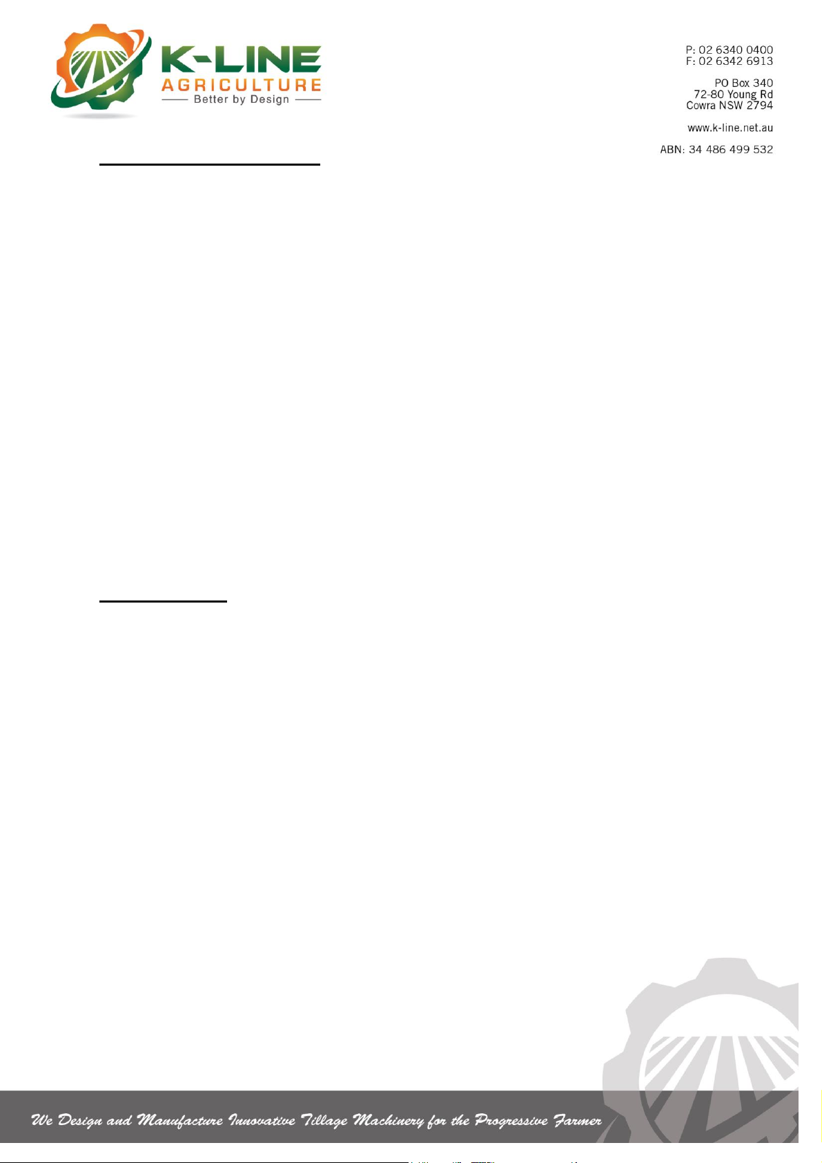
1. BE SURE tractor drawbar pin is locked securely in place.
2. Make SURE all personnel are clear of machine when folding/unfolding &
when in operation.
3. DO NOT activate unit while personnel are within 50 metres.
4. KEEP CLEAR of machine when in working & lifted position –AT ALL TIMES.
5. Hydraulic lines & hoses operate under extremely high pressure & if damaged
or worn MUST be repaired IMMEDIATELY.
6. Keep HANDS & BODY CLEAR of any oil leakage as high pressure oil can
penetrate the skin.
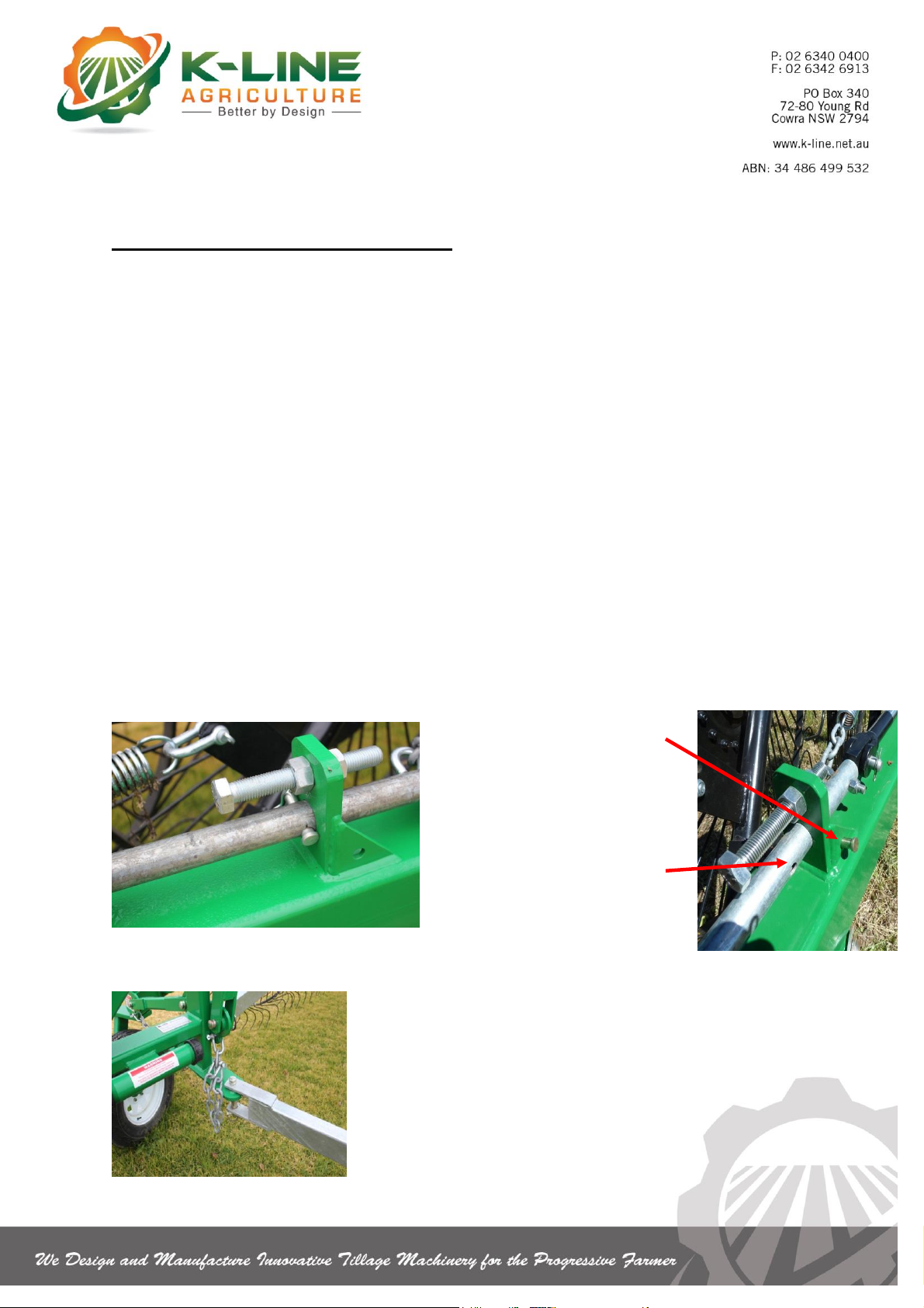
7. All bolts, nuts & pins MUST be well secured.
8. DO NOT stand on or ride on machine.
9. NEVER get under or on top of machine when it is supported by jack and
KEEP FEET & BODY CLEAR when operating jack.
10.NEVER alter the depth control or change to or from transport position, while
another person adjusts safety pins.
11.This machine has not been designed or built for road use. Please consult
State Police, Roads & Traffic Authority and any other relevant authorities
regarding the roads concerned when in transit.
12.DO NOT operate if any part of this machine is within 10 metres of overhead
power lines.
13.SPEED LIMIT –Subject to permit regulations, local Government Authorities,
road surface conditions & prime mover towing recommendations. Maximum
towing speed is 40km/hr. DO NOT EXCEED AT ANY TIME.
14.TYRE PRESSURE –Consult recommended tyre pressure table in this
manual.
15.Before operation, all hydraulic cylinders must be primed.

IMPORTANT
K-LINE AGRICULTURE spare parts and accessories have been specifically designed and
developed for the machines produced. We call your attention to the fact that non genuine
parts and accessories are not recommended by K-LINE AGRICULTURE. The use of such
replacement parts frees K-LINE AGRICULTURE from all liability and makes the warranty
void. The installation and/or use of non-genuine parts may, because of the technical
characteristics of construction, modify or influence the performance of the machine
negatively.
REMEMBER AN IMPLEMENT WITH NO BRAKES
REQUIRES CAUTION & COMPETENCE

SAFE WORK PROCEDURES
TO SET RAKE IN WORKING POSITION
1. Park tractor (or prime mover) on a safe level site. Engage park brake and stop
engine.
2. Disconnect short transport arm and pin into raised position (Figure 3)
3. Remove safety chains from front of wing. (Figure 3)
4. Release and lift down long working arm –adjust to desired working width and
engage on raking arm, observing correct manual handling techniques.
5. Repeat steps 2 - 4 for other side of rake.
6. Adjust pins and lower splitter reels to the working position (if manual splitters
fitted).
7. Lift reel arms with hydraulics and remove transport pin (figure 2)
8. Slowly lower hay reels to working position.
9. Machine is ready to use.
Reel lift
transport
locking pin
in storage
mode
Transport
locking
pin out
Figure 2
Figure 1
Transport
pin in
Figure 3
Transport arm
& safety chain
released
Ensure all bolts and pins are securely fastened before operating.

TO SET RAKE IN TRANSPORT POSITION
1. Park tractor on safe level site, engage park brake and stop engine.
2. Lift splitter reels and adjust pins to transport position (if manual splitters are
fitted).
Observe correct manual handling techniques.
3. Raise hay reels to transport position using the hydraulics and insert transport
pin.
4. Disconnect long working arm and lift into transport holder, then fasten
securely.
5. Lower short transport arm and secure into transport position and attach safety
chain. (figure 4)
6. Repeat steps 4 & 5 for other side of rake.
THE OPERATOR MUST ENSURE NO PERSONNEL ARE NEAR REELS
WHEN LOWERING, RAISING OR OPERATING MACHINE.
Eye protection (safety glasses or goggles) and foot protection (safety boots) must
be worn when adjusting depth control and changing or repositioning rake reels.
WARNING –Disengage rear steer for transport (if applicable)
Figure 4
Transport arm &
safety chain secured

HITCHING TO MACHINE
N.B. Keep body well clear when attaching tractor to rake at all times.
Follow all safety precautions set out on preceding pages.
1. Adjust rake drawbar height to suit tractor
2. Back up machine
3. Place tractor in ‘park’ position
4. Secure drawbar pin in place with lynch pin
5. Attach safety chain to lug provided on machine
6. Plug in hydraulic lines into tractor remotes
7. Raise implement jack and store in transport position.
UN-HITCHING
1. Stop tractor. Place in ‘park’ position.
2. Chock rear wheels
3. Use implement jack to raise machine slightly (ensure jack is securely locked
in position).
4. Remove drawbar pin and safety chain
5. Unplug hydraulic hoses
6. Tractor now ready to drive away.

MAINTENANCE SCHEDULE & SAFETY CHECK
Conduct a safety check daily.
□Check wheel stud tension first hour of operation or after changing of wheels.
□Tighten wheel nuts
□Tighten reel tine bolts & reel keeper bolts.
□Ensure all pins (including lynch) & bolts are securely fastened.
□Check tyre pressure (see recommended tyre pressure table).
□Check all safety decals & safety mechanisms.
□Check frame for fatigue.
□Check all hydraulic hoses for wear and damage.
□Replace if necessary.

SAFETY INSPECTION & LUBE SERVICE
Conduct a lube service & safety inspection after first 5hrs of use & each 50 hrs
thereafter.
□Rake reels spin freely, reel keeper bolts are tight & rake arms lift freely.
□All pins (including lynch pins) are in place.
□Reel support springs are firm and in place.
□Brake assembly on castor wheel correctly placed & no signs of wear.
□Wheel nuts are tight & tyre pressure checked on all tyres (see recommended
tyre pressure table).
□Rake jack is greased.
□Hydraulic hoses are sound and show no signs of wear.
□If splitter kit is fitted, ensure that bolts attaching to A-frame are secure, reel
support springs are sound; splitters lift safely and hold securely for transport.
□Check frame for fatigue & failure.
□On hydraulic models, ensure that plastic guides are not worn & are correctly
aligned.
□Ensure all appropriate safety decals are securely attached to machine &
safety chains fitted (if applicable).
□Instruction manual is installed on machine and caps secured.
□Dismantle & repack wheel bearings with good quality grease, annually.

CASTOR WHEEL BRAKES
To assist in the control of castor wheel shudder, K-Line rakes are fitted with castor
brakes using adjustable spring loaded friction pads.
To adjust castor wheel brakes:
1. Release spring pressure by turning adjusting nuts (anti-clockwise) until both
springs can just move sideways by hand –retighten by rotating in clockwise
direction. One complete turn only (see Figure 5.)
2. If increased braking is required, turn both adjusting nuts one turn each (it is
important that equal pressure is applied to each set of springs).
3. Check machine for correct operation. Repeat if necessary.
4. Use same procedure for each castor wheel.
IMPORTANT –If friction springs need to be tightened for road transport, they must
be loosened for field operation.
Figure 5
Castor Wheel Brakes
Spring tension
adjustment nuts

REEL HEIGHT ADJUSTMENT
The reels on all K-Line rakes are sprung to give an even and balanced operating
weight.
1. For raking light swaths –Adjust reel height to allow tines to be just above
ground level (see Figure 6 for adjustment mechanism).
2. For raking heavy swaths –Lower slightly to allow tines to be just touching the
ground.
WARNING
Care must be taken to lower the reels only enough to operate machine correctly, as
damage will occur when machine is lowered excessively.
REMEMBER
For heavy swaths (e.g. silage), raking ability is increased when machine is set in a
narrower operating position.
Adjustable depth
control stop
Figure 6
Reel lift transport
locking pin in storage
position

WINDROW WIDTH ADJUSTMENT
1. Remove pin to change rake arm position (see Figure 7).
2. Repeat for opposite side.
Recommended tyre pressure:
MODEL
CASTOR WHEELS
REAR WHEELS
V10 –V12
185/R14 - 0.6KPA (10PSI)
185/R154 - 1.0KPA (17PSI)
V14 –V16
185/R14 - 0.6KPA (10PSI)
185/R14 - 1.0KPA (17PSI)
V18
235.75/R15 - 0.6KPA (10PSI)
235.75/R15 - 1.0KPA (17PSI)
Figure 7

TO ACTIVATE REAR WHEEL STEERING (IF APPLICABLE)
1) Move rake to forward position (i.e. straight ahead)
2) Release locking pin from transport position (see Figure 8)
3) Check rear steer hole for alignment (Figure 8). Insert locking pin and tighten. (To
align
holes, turn front or rear wheels slightly).
TO LOCK REAR WHEELS IN TRANSPORT POSITION
1) Move rake to forward position (i.e. straight ahead).
2) Remove locking pin from rear steer hole position (see Figure 8).
3) Insert locking pin into non rear steer pin position and tighten. (If needed, align by
bumping rear wheels around slightly).
CAUTION –Machine must be locked out of rear mode for road
transport.
TO ADJUST TRACKING POSITION OF REAR WHEELS
1) Set machine in rear steer mode.
2) Release locking tabs on both tie rods (see Figure 8)
3) Rotate steering tie rod centre sections to adjust wheel alignment (Figure 8)
4) Tighten locking tabs.
5) Tow machine a few metres and re-check tracking alignment.
Figure 8
Non-rear steer
pin position
Rear steer
pin position
Steering tie-
rod centre
section
Locking
pin

TROUBLE SHOOTING
Castor wheel shudder:
Check adjustment of brake as out lined in castor wheel section (page 13)
Check speed. Do not exceed operating speed stated in this manual at any
time (page 6)
Tines penetrating soil:
Lift reels (refer to Reel Height Adjustment, page 14)
Material missed or not picked up when raking:
Reel height incorrect. Follow steps set out in Reel Height Adjustment (page
14).
Rake width too wide –set machine to correct width
Material too heavy –allow time for making of hay, narrow the operating width
Swath not fully cut when mowing.
Operating speed too fast –Slow Down.
Windrow width incorrect:
Adjust; refer to windrow width adjustment section (page 15).
Operating too fast, drive at uniform speed as speed will affect width of row.
Machine not tracking correctly (rear steer model):
Refer to section ‘To adjust tracking position of rear wheels’ (page 16).

DECALS SUPPLIED WITH THIS MACHINE
TO REORDER FREE CALL 1800 194 131
(Re-order codes below stickers)
C02
D03
SL02
D04
D08
W03

RISK MANAGEMENT
Risk management is the process of finding out what may cause an injury, deciding what may
happen as a result, and doing something about it.
The steps of risk management are:
Identify the hazards to workplace health and safety arising from work activities
Assess the risks
Determine and implement control measures to reduce risk
Monitor and review the effectiveness of the control measures
IDENTIFYING HAZARDS
Prior to commencing work, all hazards related to the work tasks should be identified. The
selection of the appropriate work procedure(s) will depend on the type of work procedure(s)
and hazards involved. Regular safety inspections will also identify hazards and ensure that
control measures are in place.
RISK ASSESSMENT
Risk assessment allows appropriate control measures to be developed. Once hazards have
been identified, they should be assessed in terms of their potential to do harm. To assess
risk, consideration should be given to probability and consequences. SEE RISK
ASSESSMENT MODEL.
RISK CONTROL
Risk control is the process of eliminating or reducing risk factors. Control measures should
be chosen and implemented to eliminate or reduce risk as far as practicable. When deciding
on the most appropriate measures to use, practicality and acceptance of the control
measures should be considered. Safe Working Procedures will be developed for all high –
medium risk hazards.
MONITOR AND REVIEW CONTROL MEASURES
The risk identification, assessment and control process requires regular monitoring to ensure
the implemented control measures perform as originally intended and continue to prevent or
adequately control the risk of injury or incident. Control measures should also be checked
carefully to ensure that new hazards are not created, directly or indirectly, by the original
control measures.

Ensure all bolts are correctly tensioned and
pins are securely fastened.
Ensure all personnel are at least 6.0m away
from machine.
Observe correct manual handling techniques.
For repairs and maintenance always
Lower machine to the ground
Use suitable jack stands for the frame support when
servicing in raised position
NEVER GET UNDER MACHINE WHILST IN RAISED POSITION WITHOUT
APPROVED JACK STANDS IN PLACE.
THE OPERATOR MUST ENSURE NO PERSONNEL ARE NEAR
MACHINE WHEN LOWERING, RAISING OR OPERATING
MACHINE.
This manual suits for next models
6
Table of contents
Other K-Line Farm Equipment manuals
Popular Farm Equipment manuals by other brands

Victory
Victory WC-8H Operator's manual

Sampo Rosenlew
Sampo Rosenlew Comia c4 Instruction book

VALMETAL
VALMETAL STATIONARY UNROLLER Operator and parts manual

X-PETS
X-PETS BUNNY Assembly instructions

MANDAKO
MANDAKO REDDI-LYNX Operator's manual

Duratech
Duratech Haybuster CMF-425 Operating Instructions and Parts Reference