Kaba Mas Gitcon G-152 User manual

1
Gitcon Model G-152
Installation Guide
for Swing & Roll-Up Doors
G-152 Parts
1. Lock Body Gasket
2. Lock Body mounting bolts and washers
3. Lock Body with cable
4. Input Unit mounting bolts and washers
5. Input Unit
6. Handle (6a. Roll-Up or 6b. Swing)
7. Handle Mounting Hardware (Not shown in photo)
8. Back Plate (8a. Vertical or 8b. Horizontal)
9. Cable Routing Plate (9a. Vertical or 9b. Horizontal)
10. Test card (not shown).
Document Number 607.106 Rev. B - 4/08
Fig. 1 - Lock Body & Input Unit Parts
Fig. 2 - Vertical and Horizontal Plates Fig. 3 - Roll-Up Handle & Swing Handle
1
2
3
4
5
8a 9a
9b
8b
6a
6b

2
Symbol Denitions
WARNINGS - Hazards or unsafe practices which could result in personal injury or product or
property damage.
NOTES - contain important information and useful tips on the operation of your equipment.
Basic Tools and Materials Required
• Fournewhighquality(Energizer®, Duracell®, etc.) AA lithium batteries
• Poprivetgun
• Electrichanddrill
• 8mm(5/16"),10mm(3/8")and16mm(5/8")drillbit
• Appropriatesizeddrillbitfordrillingrivetheadonhandle(ifrivetISNOTstainlesssteel)
• Handheldpowergrinder(ifrivetISstainlesssteel)
• Tape
• Centerpunch
• Adjustableopenendwrenchor10mmand13mm(11mmisalsoneededonroll-updoor
installations)sockets/boxwrenches
• Level
• Hacksaw
• Hammer
• Phillipsscrewdriver
• Tapemeasure/Ruler
• 2mmAllenWrench(inputunitbackcover)
Before Drilling
Before drilling any holes ensure that:
• Youarewearingsuitableeyeprotection.
• Adequateprotectionisttedaroundthesurroundingareatoprotectsuchthingsascables,
water/airpipes,etc.,fromdamage.
Before starting any work, determine the position the G-152 is to be located, bearing in mind
the following points:
• Ensurethereisnoobstructionontheinsideofthedoor.
• Ensurethevehicleisparkedonat,levelgroundwheninstallingthislock.
• Pleaserememberyouareinstallingahighquality,precisionlocktoadoorwhich,evenwhen
new,willhaveafairamountoffreeplayinitsoperation.Thisfreeplaywillonlyincrease
withwearasthevehicleisused;therefore,greatcaremustbetakenduringinstallation.
Input Unit Preparation
RemovethebackoftheInputUnit(4screws)witha2mmAllenWrench.Placefournewhighquality
AA lithium batteries in the battery retainers. Reattach the back plate, ensuring that the wires are
notpinched.Oncethebatteriesareproperlyinstalled,redLEDlightwillash.Connectthecable
tothelockbody.PerformtheOperationalCheck(p.7).Disconnectthecable.
WARNING
!
WARNING
!

3
Remove Existing Handle
Note: Useacenterpunchtomarktherivetheadbeforeattemptingtodrilltheheadoff.This
willhelppreventthelikelihoodofthedrillslippinganddamagingthevehicledoor.Ifthe
rivetisstainlesssteel,apowergrindermayberequiredtogrindofftherivethead.
1. Grindordrilljustenoughtoremovetherivetheadandtoavoiddamagingthedoor.Oncethe
headhasbeengroundordrilledoff,knocktheremainsoftherivetoutusinganappropriate
sizedpunch.Removethehandlefromthedoor.(SeeFigure4.)
Note: Roll-updoorswillhavemultiplerivetsthatneedtoberemoved.(SeeFigure5.)
Remove Handle Retainer or Keeper Assembly
1. Drill/grindtheboltsoutofthehandleretainerassembly(forswingdoor)orthehandlekeeper
(forroll-updoor).(SeeFigure6forSwingDoorandFigure7forRoll-UpDoor.)
2. Removetheretainerorkeeperassembly.
Fig. 4 - Swing Door Fig. 5 - Roll-Up Door
Fig. 6 - Swing Door Fig. 7 - Roll-Up Door
Keeper

4
Install Handle
Swing Door
1. AttachtheG-152handletothehubwheretheoldhandlewasremoved,usingthepinincludedin
the kit. Insert the pin from the front side of the locking bar.
2. Gainaccesstotherearofthepin.Insertwasherandrivetincludedinthekit.Securetherivetin
positionusingthepoprivetgun.
Note: Ifinstallingonadoorwithdoubleverticallockingbars,installonthelockingbarclosest
to the hinges.
Roll-Up Door
1. Withthedoorclosed,alignthedoorhandleassembly"J"hookwiththecenterpin/plateofthelatch
box.Operatehandle(open/close)toensurecorrectpositionwithinthelatchbox.
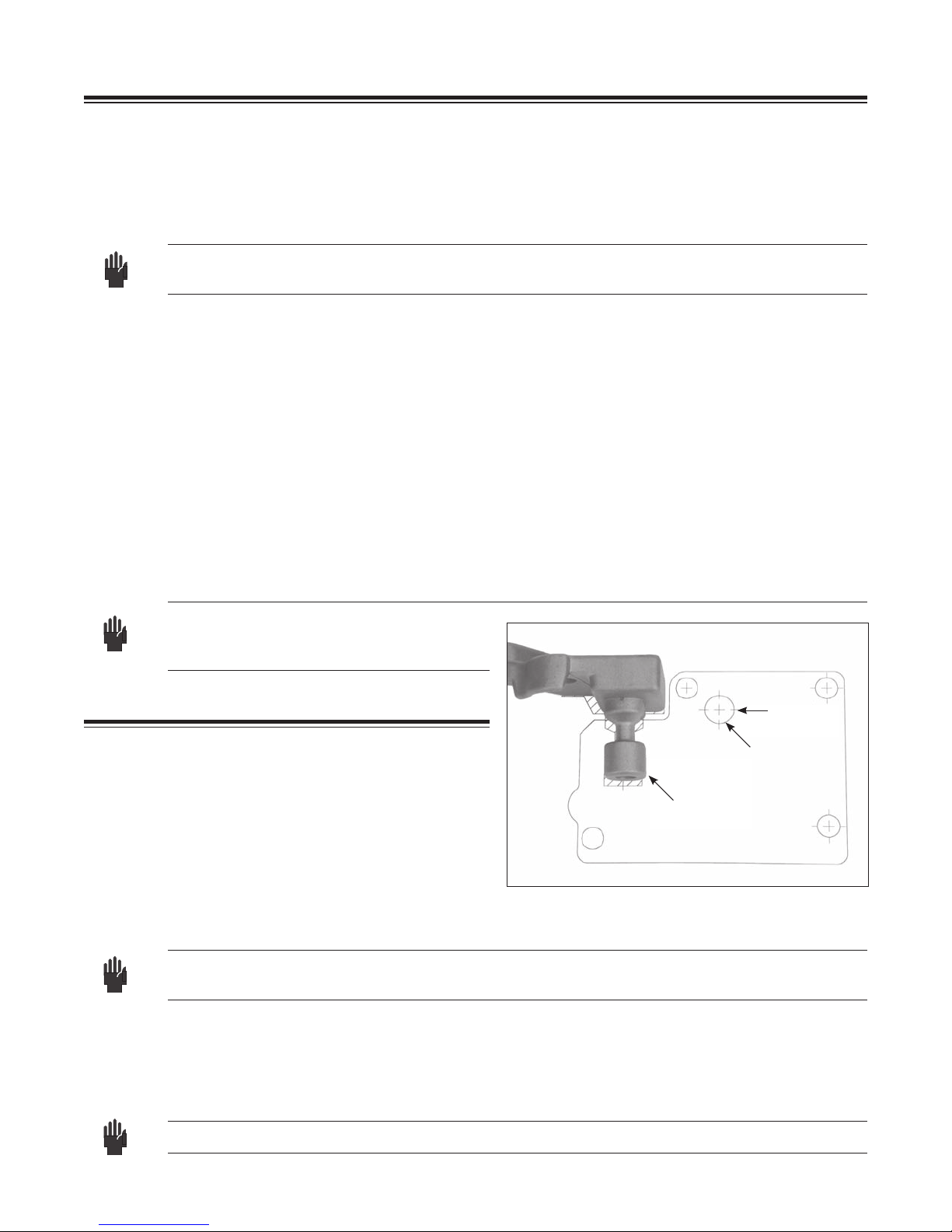
2. Ensurethehandleislevel.Usetheatendofthehandle.(Seegure8.)
3. Using the handle assembly mounting bracket as a template, mark (center punch) the location of
the mounting holes.
4. Drillthehandleassemblymountingholesusingan8mm(5/16")drillbit.
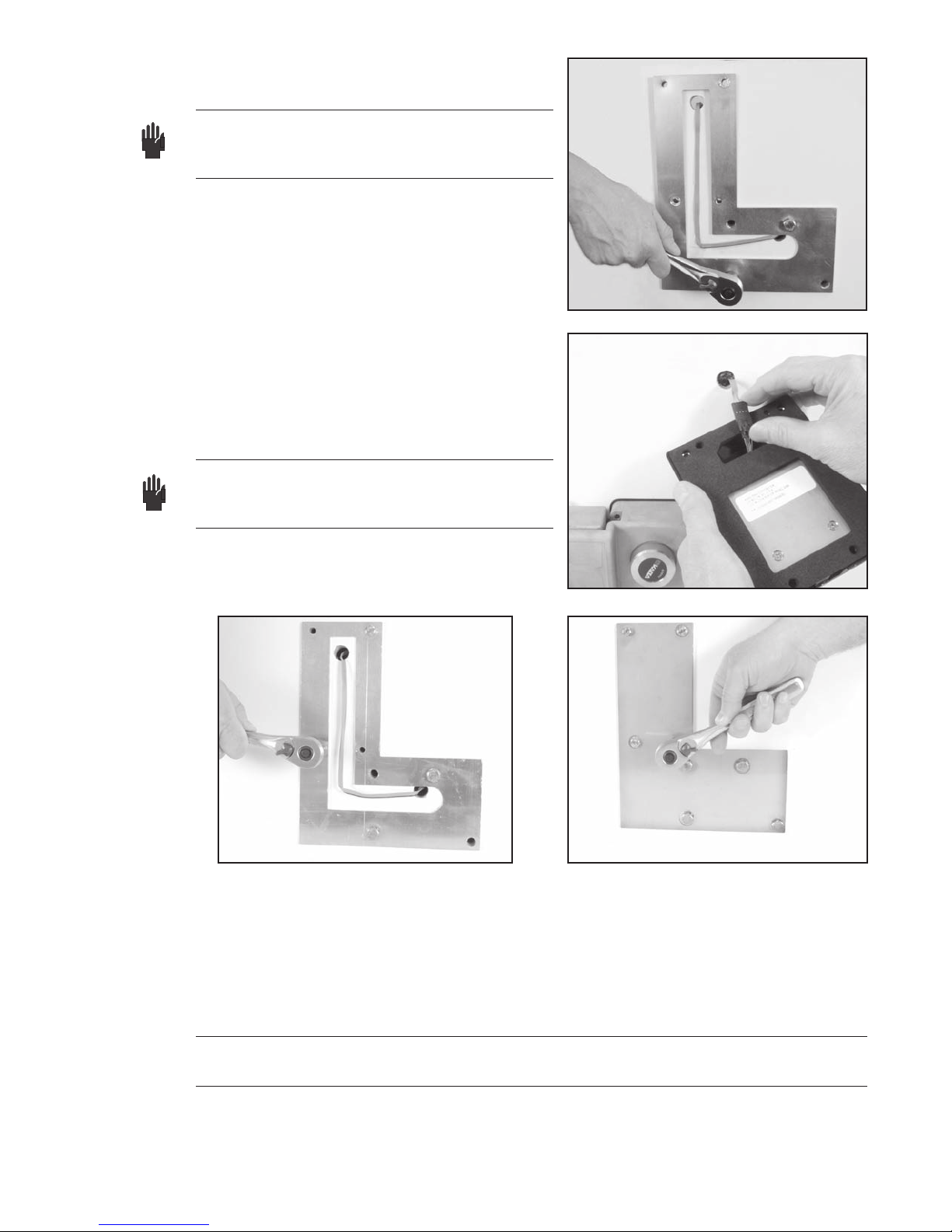
5. Insert and seat carriage bolts into supplied handle assembly. Seat carriage bolts by using a hammer
todrivetheboltsintothemountingplate.
6. Mount handle assembly to door and secure from the inside with washer/lock washer/nuts
provided.
Note: Ifnecessary,useahacksawtoremove
excess bolt length and grind any
resulting sharp edges.
Prep Door for Lock Body
1. Using the new handle, close the door(s) fully,
ensuring correct shutting for closed position.
2. Aligntemplaterelativetothelockingpinon
thehandle.(SeeFigure8.)
3. Use tape to secure the template to the door.
4. Place the lock body over the coordinating
location on the template and rotate the handle
to ensure that it clears the lock body. If not, readjust the template.
Note: If the handle becomes locked in position, connect the cable from the input unit to the lock
bodyandperformtheOperationalCheck(p.7)tounlockandliftthehandle.
5. Center punch all four mounting holes and cable routing hole.
6. Removethetemplate.
8. Drillthefouroutsidelockcasemountingholesusinga10mm(3/8")drillbit.
9. Drillthecableroutingholeusinga16mm(5/8")drillbit.
Note: Ensurethatthedrilliskeptstraightwhendrillingtheholes.
Fig. 8 - Align Template to Handle
FlatonHandle
Locking PIN
Electronic
LockOnly
Cable
Routing Hole

5
Deburralldrilledholes.Removealldebrisfromtheworkareaafterdrillingandbeforeproceeding
furtherwithanyinstallation.DONOTusecompressedairtoremovedebris.Flyingobjectscan
cause serious injury.
Prep Door for Input Unit
1. Temporarily attach the cable routing plate to the front of the door for use as a template, using
thelockmountingscrewstoholditinplace.(SeeFigure9.)
2. Center punch four mounting holes for the Input Unit.
3. Measureandmarkanadditional16mm(5/8")holeforcableroutingapproximately32mm
(11/4")fromthetopofthecableroutingplate.(SeeFigure10.)
4. Removethecableroutingplate.
5. Drillthecableroutingholefortheinputunitusinga14mm16mm(5/8")drillbit.
6. Drillthefourmountingholesfortheinputunitusinga10mm(3/8")drillbit.
Install Lock Body & Input Unit
Note: ForRoll-UpDoorapplicationsusingaTodco(orWhitingGeneralPurpose)handle,
use the longer 8mm mounting bolts supplied for the bottom two holes of the lock body
and use the longer 6mm mounting bolts supplied for the bottom two holes of the input
unit.
1. Start to attach the two cable routing plates to the inside of the door using two of the lock body
mounting bolts and two lock washers. Attach through the upper right and lower left corners of
the lock body mounting holes.
2. Ontheoutsideofthedoor,placethelockbodygasketoverthetwoboltstoholditinplace.
3. Whileholdingthelockbody,routethecablethroughthegasketandthecableroutingholefor
the lock body.
Fig. 9 - Use Cable Routing Plate as Template Fig. 10 - Measure & Mark Cable Routing Hole
WARNING
!
1 1/4"

6
4. Secure (hand tighten only) the G-152 lock body
usingthetwobolts.(SeeFigure11.)
Note: Youwillhavetobacktheboltsoutfromthe
inside of the door a small amount in order
to thread them into the lock body.
5. Route the cable through the cable routing hole for
the input unit.
6. Insert two of the input unit mounting bolts and
washers through the back of the door. Use the
upper right and lower left corners of the input unit
mounting holes.
7. Connect the lock body and input unit cable.
8. Placeexcesscablebackintheinputcavityviathe
cable routing hole.
9. Secure (hand tighten only) the input unit using the
twobolts.(SeeFigure13.)
Note: Youwillhavetobacktheboltsoutfromthe
inside of the door a small amount in order
to thread them into the input unit.
10. Tape the cable in place in the routing channel so
that it does not get pinched when the back plate is
attached.
11. Attachthebackplateoverthecableroutingplatewiththefourremainingbolts,ensuringthe
cable does not get pinched. The cable must stay in the channel of the cable routing plate. (See
Figure14.)
12. Securely tighten all bolts.
13. Before closing door, place handle in lock body and perform operational check.
Note: If handle will not go into the lock body, loosen the lock body bolts, reposition lock body
to accept handle and re-tighten bolts.
14. Close the door(s) and place the handle in the lock body.
Installation complete.
Fig. 11 - Secure Lock Body from Back of Door
Fig. 12 - Connect Cable to Input Unit
Fig. 13 - Secure Input Unit from Back of Door Fig. 14 - Attach Back Plate

7
Operational Check
PerformtheoperationalcheckpriortoinstallingtheLockassembly.IftheG-152hasbeenpreviously
installed, perform the operational check prior to closing
the door.
Make an operational check of the unit by performing the
followingactions.(SeeFigure15forreference.)
1. Connect the Lock Body and input unit cable.
2. Activatetheinputunitbypressingandreleasingthe
REDswitchbutton.
3. "Open"willappearontheLEDdisplay.
4. Insert (latch) the operating handle locking pin into the
lock body.
5. PressandreleaseREDswitchbutton.
6. Press and release RED button again with "UNLK"
prompt.
7. GREENlightashes.
8. Present Test Card to input unit transponder "RFID"
communication area.
9. Turn dial on lock body to the left to release the handle.
10. Lift operating handle.
Operational check complete.
Battery Maintenance - Temporary Power
Replace Batteries
The four AA batteries located within the Input Unit should be replaced when the “Battery Low Indicator“
illuminates. To replace batteries, complete the following steps:
1. Removetheinputunitfromthedoor(4mountingbolts)anddisconnectcable.
2. Removethebackplateoftheinputunit(4screws)andthefourAAbatteriesinthebatteryretainer.
ReplacethebatterieswithfournewhighqualityAAlithiumbatteries.Oncethebatteriesareproperly
installed,thelowbatteryindicatorlightwillash.
3. Reattach the back plate of the input unit.
4. Reconnect the cable and reinstall input unit.
5. Before closing the door, perform an operational check of the lock with the appropriate opening
procedureasdenedfortheinputunit.
Temporary Power
Anexternal9Vsupplementarypowerconnectorisprovidedtosupplytemporarypowertotheinput
unit. The 9V connector is located at the base of the input unit and is accessible by turning the
knurled knob. It is recommended that you use a new high quality battery.
Fig. 15 - Input Unit Operation
Access to
9 volt connector
Low battery
indicator
Transponder RFID
communication area
IrDA®port;
Communication with
Pocket PC/Smart Phone
LED Lights;
Operational
prompts and
lock status
Switch activates
unit and enters
user cdes
LED displays
seal number
and operational
prompts

8
Notice: Informationinthisdocumentissubjecttochangewithoutnotice.KabaMasshallnotbeliablefortechnicaloreditorialerrorsor
omissionscontainedherein;norforincidentalorconsequentialdamagesresultingfromthefurnishing,performanceoruseofthismaterial.
© 2006 Kaba Mas LLC. All rights reserved.
Kaba Mas LLC
749 W. Short Street, Lexington, KY 40508 USA
Phone: (859) 253-4744 FAX: (859) 255-2655
Technical Support: (800) 950-4744
www.kaba-mas.com
Maintenance and Trouble-Shooting
Maintenance
• Inspectthedoorassemblytoassureproperalignmentandoperation.
• InspecttheG-152mounteddoorpanelfordefectsandrepair/replaceasrecommendedbythe
manufacture.
• Verifylockbodyandinputunitmountinghardwareissecure.
• Openandcloselockassemblytoassureallcomponentsareproperlyalignedandingood
operating condition.
• Inspectphysicalconditionofhandle-mounted"WeatherGuard"andreplaceifneeded.
• KeepLockBodylockingjawscleanandremoveanydebris.
• ApplyaDryFilmLubricanttotheLockBodylockingjaws.
• ReplaceInputUnitbatteriesatleastonceayear.Seepage7BatteryMaintenance.
Winter Conditions
• Iflockbecomesfrozen,applyde-icerasrequiredtothe:
•Lock Body locking jaws
•Lock Body operating dial
• InputUnitREDbuttonswitch
• Applya 9-voltbatterytothesupplementarypowerconnector ifcoldweatherconditions
impairtheInputUnit/LockBodyoperation.Seepage7TemporaryPower.
Trouble-shooting
• IftheInputUnit/LockBodyoperationmalfunctions,applya9-voltbatterytothesupplementary
powerconnector.Ifoperationsresume,replacetheInputUnitbatteries.Seepage7"Battery
Maintenance-TemporaryPower".
Table of contents
Other Kaba Mas Door Lock manuals
Popular Door Lock manuals by other brands

Herman Miller
Herman Miller Canvas Office Landscape Interiors Installation and Disassembly for Recycling Instructions

Southco
Southco H3-EM-66-100 operating instructions

M-TI
M-TI 185-00426 product manual

Masterlock
Masterlock 6400 instructions

effeff
effeff 351U80 RR AKRR installation instructions

Abus
Abus PR2600 Fitting and operating instructions

GEM
GEM GL600-F Specification sheet

Assa Abloy
Assa Abloy Corbin Russwin TL3700 Series installation instructions

Salto
Salto XS4 Original installation guide

Starke
Starke Seamless Smart Lock user manual

ZKTeco
ZKTeco ZL700 installation guide

Assa Abloy
Assa Abloy effeff 843 Installation and mounting instructions