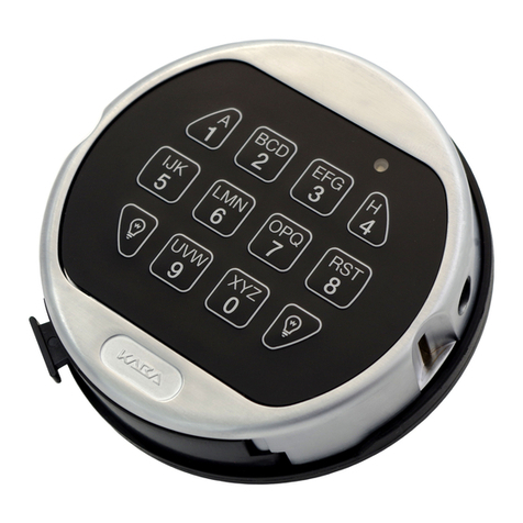
Kaba Mas High Security Pedestrian Exit Device with Electric Locking... User manual

INSTALLATION GUIDE
High Security Pedestrian Exit Device
with Electric Locking Trim

WARNING: Kaba Mas locks are well protected from Electrostatic Discharge (ESD) damage once
they are installed, but can be damaged during the installation process if proper
precautions are not observed. Follow these precautions to avoid ESD damage when
installing the lock:
• Do not touch the end of the flex cable if the ESD protective cover has been
removed.
• Remove the X-09 lock cover assembly before touching the end of the flex cable.
• For the best protection, use an ESD wrist band grounded to the lock during
installation.
• The lock is protected to greater than 25,000 V when correctly installed.
TRADEMARKS
The following items are trademarks or registered trademarks of the Kaba Mas in the United States and/or
other countries.
• PowerStar
•X-09

Table of Contents
INTRODUCTION ........................................................................................................... 1
Installation Overview ............................................................................................................... 1
Basic Tools and Materials Needed .......................................................................................... 1
Door Handing .......................................................................................................................... 2
Templates ................................................................................................................................ 2
Rim Exit Device ....................................................................................................................... 2
CDX-09 Lock Assembly .......................................................................................................... 2
Dial Ring Mounting Template .................................................................................................. 2
PARTS CHECK .......................................................................................................... 3
Packaging................................................................................................................................ 3
Rim Exit Device Box ............................................................................................................... 4
CDX-09 Box ............................................................................................................................ 6
Lock Parts for Installation ....................................................................................................... 6
Installation Kit Contents .......................................................................................................... 6
ELECTRIC LOCKING TRIM SPECIFICATIONS ...................................................................... 7
RDS - Power Supply Control Module ...................................................................................... 7
DOOR PREPARATION................................................................................................... 8
Mark Rim Exit Device and Strike Locations ............................................................................ 8
Rim Exit Device Template .......................................................................................................9
Install CDX-09 Lock Strike ......................................................................................................9
CDX-09 Lock Assembly Template ........................................................................................ 10
Drill Holes for Rim Exit Device and Outside Lever Trim ........................................................ 10
Drill Holes for CDX-09 Lock Assembly ................................................................................. 10
CDX-09 Dial Ring Mounting Template ................................................................................... 10
RIM EXIT DEVICE / OUTSIDE LEVER TRIM ..................................................................... 11
Hardware Preparation ........................................................................................................... 11
Cut Lever Spindle and Rim Cylinder Tailpiece to Length ..................................................... 11
Determine Rim Exit Device Length, Cut to Length and Drill End Cap Mounting Hole ........ 11
Installation ............................................................................................................................. 13
Mount Rim Exit Device and Outside Lever Trim ................................................................... 13
Mount Strike .......................................................................................................................... 14
ELECTRIC LOCKING TRIM & RDS INSTALLATION ........................................................... 15
Installation Procedure ............................................................................................................ 15
System Schematic ................................................................................................................15
RDS-2 Specifications ............................................................................................................16
Operational Test for FSE (Fail Secure) Devices.................................................................... 16

HIGH SECURITY PEDESTRIAN DOOR LOCK INSTALLATION ................................................ 17
Preliminary Lock Installation..................................................................................................17
Cutting the Tubes ................................................................................................................... 18
Installation of the Lock ........................................................................................................... 19
Installation of the Dial Ring .................................................................................................... 20
Installation of the Cables ....................................................................................................... 20
Installation of Generator Cable and Cable Guides ................................................................ 21
Installation of the Dial Ring Cover ......................................................................................... 21
Cutting and Installing the Spindle .......................................................................................... 21
Installation of the Dial Hub and Dial ....................................................................................... 22
Attach Back Cover Assembly for Testing.............................................................................. 24
Final Installation of the Back Cover Assembly ...................................................................... 25
INTERFACE HARDWARE, COVERS ................................................................................ 25
Cable Assemblies ................................................................................................................. 25
Install Lock Cable Assembly ................................................................................................. 25
Install Bellcrank Cable Assembly .......................................................................................... 26
Connect Cable Assemblies ................................................................................................... 27
Adjust Cable Length .............................................................................................................. 28
Covers .................................................................................................................................. 29
Install Chassis Cover ............................................................................................................ 29
Install Lock Cover.................................................................................................................. 29

1
INTRODUCTION
Installation Overview
The High Security Pedestrian Exit Device - Electric Trim Version consists of:
1. A Rim Exit Device with Electric Locking Trim and Outside Lever Trim with Rim Cylinder
2. A High Security Pedestrian Door Lock (CDX-09)
3. Interface Hardware, Covers and Cover Brackets
4. A Relatching Delay System (RDS) with power supply and control module
The Installation Guide will describe the steps required to install each of these components of the High
Security Pedestrian Exit Device.
Basic Tools and Materials Needed
Before beginning installation, be certain that you have the following tools readily available:
• Measuring tape
• Level
• Combination square
• Tape
• Hammer
• Center punch
• Electric hand drill
• 1/4” drill bit
• 9/32” drill bit
• 5/16” drill bit
• 3/8” drill bit
• 1/2” drill bit
• No. 25 drill bit
• 2” hole saw with 1/4” pilot
• 1 1/4” hole saw with 1/4” pilot
• Long nose pliers
• Pliers
• 3/4” end wrench
• 1/4” end wrench
• Hacksaw
• File
• 1/4” or smaller slotted head screwdriver
• #1 Phillips head screwdriver
• #3 Phillips head screwdriver
• #1 Phillips head stubby screwdriver
• Safety glasses
Other tools that may be required:
• #10-24 Screw cutter
• External snap ring pliers
For a metal door installation, the following tools are needed:
• Tap handle
• #10-24 tap
• #10-32 tap

2
Figure 1 - Door Handing
Door Handing
Determine whether the door is left hand reverse (LHR) or right hand reverse (RHR) by referring to Figure 1.
Note: Installer must insure that the door meets all building, fire and security code requirements prior to
installing the High Security Pedestrian Exit Device.
Ensure that the Exit Device you are installing is compatible with the handing (LHR or RHR) of the door.
Templates
Rim Exit Device
A template is provided for the appropriate door installation (LHR or RHR) to assist in (1) laying out hole
locations for mounting the Rim Exit Device, (2) locating the lock horizontal centerline, and (3) locating the
lock strike top and bottom mounting hole centerlines. Ensure that the template is the correct one for the
handing of the door.
CDX-09 Lock Assembly
A separate template is included to assist in laying out the hole locations for the CDX-09 lock assembly. This
template is positioned on the inside of the door as described in the “CDX-09 Lock Assembly Template”
section.
Dial Ring Mounting Template
An additional template is provided as an aid for locating, drilling, and tapping the dial ring mounting screw
holes relative to the spindle hole. This template is positioned on the outside of the door as described in the
“CDX-09 Dial Ring Mounting Template” section.

3
PARTS CHECK
Packaging
The High Security Pedestrian Exit Device - Electric Trim Version is packaged in three boxes:
1. The Rim Exit Device Box contains:
• Rim Exit Device with associated parts and mounting hardware
•Outside Lever Trim with Rim Cylinder Lock and mounting hardware
•Interface Hardware, Covers and Cover Brackets with mounting hardware
2. The CDX-09 Box contains:
•High Security Pedestrian Door Lock (CDX-09)
3. The RDS Box contains:
•RDS-2 Power Supply Control Module
See the following sections for detailed part contents of the Rim Exit Device and CDX-09 boxes. The RDS-2
is the only item contained in the third box

4
RIM CYLINDER
MOUNTING BRACKET
F-490 STRIKE
(1 QTY.)
Rim Exit Device Box

5
OR
OR
Rim Exit Device Box (continued)

6
CDX-09 Box
Lock Parts for Installation
1. CDX-09 Dead bolt lock assembly
2. CDX-09 base hardplate
3. Dial hub assembly
4. Strike kit (type 2)
5. Spindle
3. Dial assembly
7. Dial ring assembly
Installation Kit Contents
1. Blade, saw (52 teeth/inch)
2. Handle, saw
3. Tube, outer
4. Tube, inner
5. CDX-09 to door mounting screws, pan
head #10 x 1.25, Type AB (6)
5. Dial ring attaching locknuts, #8-32 (2).
(Packaged with and used with exterior
mounting plate)
6. Rubber vise clamp
7. Lubricant.
8. Gage, dial hub locating
9. Zebra Connector and Retainer
10. Cable Tie Clips (3)
11. Dial ring to door mounting screws, pan head #8 -32 X 1.0 Type AB (2).
12. Cover Lock Pin Clip
13. Cover Lock Spring
14. Cover Lock Pin
15. Stone, deburring
16. Hexkey (5/64")

7
ELECTRIC LOCKING TRIM SPECIFICATIONS
The Electric Locking Trim (ELT) feature is available from Kaba Mas as a Special Engineering request (SER)
based on the Model 1000 High Security Pedestrian Exit Device. This feature includes a Relatching Delayed
System (RDS) with power supply and control module.
The ELT feature provides control capabilities of trim lock/unlock by a guard or security system while allowing
free egress at all times. The ELT system can be activated to hold the trim unlocked momentarily or for
extended periods of time.
The ELT feature can be interfaced with automatic doors, card readers, automatic fire alarm systems, etc.
The ELT application requires the use of the RDS control module. For details on the RDS, see the section
below. Closing the normally open dry contact retracts the latch. Opening the normally open switch returns the
latch to the locked position.
RDS - Power Supply Control Module
The RDS, when energized by pressing the dry contact switch, will activate the first ELT device and one
second later, will activate a second ELT device. Please note that for each RDS, two ELT devices can be
controlled by one switch.
Notes:
1. Each RDS comes in a 6” x 6” x 4” NEMA rated box.
2. RDS weight is 8 lbs.
3. The RDS-2 specifications and wiring schematic can be found in the Electric Locking Trim & RDS
Installation section of the manual.

8
DOOR PREPARATION
Mark Rim Exit Device and Strike Locations
Note: Door must be fitted and hung properly before proceeding.
1. With the door closed, establish the Rim Exit Device horizontal reference centerline by measuring 40-1/4”
from the finished floor surface.
Note: The 40-1/4” distance from the finished floor surface to the Rim Exit Device horizontal reference
centerline is a suggested distance, and may be varied to meet application requirements. However,
in no case should this distance be greater than 48” due to National Fire Protection Association code
requirements.
2. Using a level, draw a horizontal line on the door
as shown in Figure 2. Transfer the Rim Exit
Device horizontal reference centerline to the
door jamb stop face.
3. Establish the Rim Exit Device vertical reference
centerline by measuring 2-1/4” from the face of
the door jamb stop along the Rim Exit Device
horizontal reference centerline as shown in
Figure 3. Using a level, mark the Rim Exit
Device vertical reference centerline on the door
approximately 13½ inches above and 9½
inches below the Rim Exit Device horizontal
reference centerline as shown in Figure 4.
Figure 3 - Establish Rim Exit Device Vertical Refer-
ence Centerline
LHR SHOWN
Figure 2 - Establish Rim Exit Device Horizontal Reference Centerline

9
Rim Exit Device Template
1. Position the Rim Exit Device
drilling template on the inside of
the door using the Rim Exit
Device horizontal and vertical
reference centerlines previ-
ously established and shown in
Figure 4. Tape the template to
the door.
2. Center punch all hole positions
onto the door.
Note: It is very important to
accurately center punch all
holes since hole locations
establish the distance be-
tween the Rim Exit Device
and the CDX-09 lock assem-
bly.
3. Transfer the lock horizontal reference centerline from the Rim Exit Device template to the door and door
jamb. This centerline will be used to position the CDX-09 lock assembly drilling template on the door, and
locate the center mounting hole for the strike.
4. Transfer the lock strike mounting hole centerlines from the Rim Exit Device template to the door jamb. These
centerlines will be used to position the CDX-09 strike in the correct vertical location on the door jamb.
Install CDX-09 Lock Strike
1. Horizontal positioning of the CDX-09 lock
assembly drilling template is referenced to the
CDX-09 lock strike, so this strike must be
installed before the CDX-09 lock assembly
template can be positioned on the door. #10-32
machine screws are recommended for a metal
door jam and #10 thread forming screws are
recommended for a wood jamb.
2. Position the CDX-09 lock strike on the door
jamb face as shown in Figure 5. Align the strike
vertically so that the top and bottom strike
mounting counterbored holes are centered
over the lock strike mounting hole centerlines.
Align the strike horizontally so that the strike
edge adjacent to the open tang is 3/32” from
the door jamb stop.
3. Center punch the two slotted strike hole
locations (mid-slot) onto the door jamb face.
4. Drill and tap the two (2) slotted hole locations
for attaching screws. (No. 25 drill, 0.149 inch diameter for #10 thread forming screw. No. 21 drill, 0.159 inch
diameter for #10-32 machine screw).
5. Mount the strike to the door jamb face using two (2) #10-32 pan head machine screws for the two slotted
holes.
6. Install the remaining 3 flat head (machine or thread forming) screws after mounting the CDX-09 lock
assembly and the rim exit device.
Figure 4 - Door Layout for Rim Exit Device
Figure 5 - CDX-09 Strike Installation

10
CDX-09 Lock Assembly Template
1. Fit the CDX-09 strike tang opening of the CDX-09 lock assembly cardboard drilling template over the strike
tang mounted on the door jamb face. Center the strike tang opening of the template horizontally over the
strike tang as shown in Figure 6.
2. Position the lock template on the inside of the door
and align the lock horizontal reference centerline on
the lock template with the lock horizontal reference
centerline on the door. Tape the template to the door.
Note: The door must be ajar and free to swing while
positioning the template to the strike tang and
door.
3. Center punch all hole positions onto the inside door
surface.
Note: It is very important to accurately center punch all
holes since hole locations establish the distance
between the Rim Exit Device and the CDX-09
lock assembly.
4. Remove CDX-09 Lock Assembly Template and the Rim Exit Device Template.
Door Preparation for Rim Exit Device and Outside Lever Trim
1. Using information on the Rim Exit Device template, drill holes and cut rectangular opening as directed.
Drill Holes for CDX-09 Lock Assembly
1. Drill the 0.5 inch diameter spindle hole 1.25 inches deep. DO NOT drill through the door.
2. Drill all six CDX-09 attaching screw holes (No. 25 drill, 0.149 inch diameter). Drill the holes 1.25 inches deep.
DO NOT drill through the door.
CDX-09 Dial Ring Mounting Template
1. Using a square or level, transfer the lock horizontal reference centerline from the inside door surface to the
outside door surface.
2. Establish the center of the spindle hole on the outside door surface as follows:
A. On the inside door surface measure the horizontal distance from the edge of the door to the center of
the 0.5- inch spindle hole.
B. Establish the spindle hole center on the outside door surface by measuring this distance from the
edge of the door (compensating for the door edge bevel, if necessary) along the lock horizontal
reference centerline and mark vertical centerline for 1 inch in each direction.
C. Mark horizontal line so as not to extend beyond dial ring.
3. Center punch the hole position onto the outside of the door and drill the 0.5-inch spindle hole through the
door.
4. Align the CDX-09 dial ring mounting template on the outside door surface with the lock horizontal reference
centerline and the 0.5-inch spindle hole. Tape the template to the door.
5. Center punch the dial ring mounting hole positions (either the horizontal or vertical set of holes) onto the
outside of the door, and remove the template.
6. Drill two (2) attaching screw holes (No. 29 drill, 0.136 inch diameter) 1.25 inches deep. DO NOT drill through
the door.
7. Tap two (2) #8-32 holes, if required.
Figure 6 - CD-X09 Lock Assembly Template
Placement

11
RIM EXIT DEVICE / OUTSIDE LEVER TRIM
Hardware Preparation
Before installing the Rim Exit Device and Outside Lever Trim, it is necessary to:
1. Cut Lever Spindle and Rim Cylinder Tailpiece to length.
2. Determine Rim Exit Device length required and cut device to length and drill.
Note: The electric locking trim fail secure rim device cannot be re-handed.
Details on each of these items follow.
Cut Lever Spindle and Rim Cylinder Tailpiece to Length
1. Position the outside lever trim on the door and measure the Lever Spindle and Cylinder Tailpiece as they
extend through the door.
2. If necessary, cut the Lever Spindle to extend beyond inside face of door by 5/8”.
3. If necessary, cut the cylinder tailpiece to extend beyond inside face of door by 5/16” - 3/8”.
Determine Rim Exit Device Length, Cut to Length and Drill End Cap Mounting Hole
1. Determine the Rim Exit Device length.
A. Locate the Rim Exit Device vertical reference centerline on the door.
B. Measure the distance “Y” from the Rim Exit Device vertical reference centerline to the door jamb stop
surface on the hinge side.
C. Subtract 1” for recommended clearance.
D. Length of Rim Exit Device from vertical reference centerline “X”.
Figure 7 - Rim Exit Device Length Calculation

12
2. If the Rim Exit Device is longer than “X”, cut the device.
A. Remove the device channel cover, ro-
tate 180 degrees, and then re-insert it.
(U-shaped slot towards touchbar.)
B. Mark the device channel and channel
cover to length “X”.
Note: Be sure channel cover is pushed snug to
touchbar prior to marking or cutting to
size.
C. Cut both device channel and channel cover to
marked dimension and remove burrs.
Note: Factory recommends sawing rather than grind cut
to size. Grinding can damage the finish of the
device and sawing results in less damage to the
device finish.
3. Drill end cap mounting hole in device
channel.
A. Remove the device channel cover
and drill a 5/16” diameter hole on the
device reference centerline 5/16”
from the end of the channel as shown
in Figure 10.
Figure 8 - Mark Device Channel and Cover Length
Figure 9 - Cut Device Channel and Cover
Figure 10 - Drill End Cap Mounting Hole in Device Chan-
nel

13
Figure 11 - Rim Cylinder Mounting
Figure 12 - Mount Rim Exit Device
Through Door to Outside Lever Trim
Installation
Mount Rim Exit Device and Outside Lever Trim
1. Insert Rim Cylinder into trim plate and secure on opposite
side of trim with mounting bracket and two screws as
shown in Figure 11. Tighten screws securely.
Note: The Rim Cylinder Mounting Screws may need to be
shortened. You may discard the mounting plate that
was included with the Rim Cylinder as it is not needed
for this installation.
2. Place Outside Lever Trim on door using holes previously
drilled.
3. Throughbolt the Rim Exit Device to the Outside
Lever Trim using four (4) #10-24 x 1” PPHMS
as shown in Figure 12. Do not tighten screws.
4. Locate, mark and drill end cap mounting hole
following these steps:
A. Level the Rim Exit Device
B. Mark the center of the 5/16” diameter hole
at the end of the channel.
C. Drill a 9/32” diameter hole through the door.
D. Drill a 3/8” diameter hole on the trim side
of the door using the 9/32” diameter hole
as a guide.
6. Insert the device channel cover as shown in
Figure 13, with the U-shaped slot toward the
open end.
7. Install the end cap mounting bracket using the
sexbolt and the 1/4”-20 x 3/4” TPHMS mount-
ing screw as shown in Figure 13. Make sure
the Rim Exit Device is level.
Tighten the mounting screw.
8. Tighten all mounting screws and
check for smooth operation.
Mounting
Bracket
Rim
Cylinder
Tailpiece
Figure 13 - Install End Cap Mounting Bracket
MOUNTING
BRACKET
SEX
BOLT
1/4”-20 X 3/4” TPHMS
MOUNTING SCREW
CHANNEL
COVER

14
Figure 14 - Install Channel End Cap
9. Attach the channel end cap using two #8-32 x 3/
8” UFPHMS with nylon patch as shown in Figure
14.
Mount Strike
1. Ensure that the Rim Exit Device centerline has been transferred to the door jamb stop.
2. Refer to Figure 15. Center strike on door jamb
stop across Rim Exit Device reference
centerline and flush to door surface.
3. Mark top and bottom screw locations, then
center punch and drill (and tap if required) for
mounting screws.
4. Apply strike to door jamb stop using two #10-24
x 3/4” FPHMS screws.
5. Check Rim Exit Device for smooth operation
and secure latchbolt engagement. Adjust strike
if required.
6. For third (center) mounting screw on strike,
mark location, center punch, drill (and tap if
required) hole. Use a #10-24 x 3/4” FPHMS
screw to mount.
Figure 15 - Mount Rim Exit Device Strike

15
ELECTRIC LOCKING TRIM & RDS INSTALLATION
Installation Procedure
1. Install ELT devices per device installation instructions.
2. Install power supply (RDS-2). See Wire Guage Chart below.
3. Complete wiring as indicated on System Schematic.
Caution: Ensure that cover is secured on RDS-2 box before applying 115 VAC power.
4. Test operation of ELT devices. (Refer to RDS-2 Specifications on next page.)
System Schematic

16
RDS-2 Specifications
• Solenoid rated for continuous duty (with RDS).
• Input voltage required: 115 VAC, 60 Hz, 5 amps to transformer.
• Output voltages:
- First Device: Terminal #1 and #2; 24V DC impulse; 5V DC continuously after impulse.
- Second Device: One second delay after first device; Terminal #3 and #4; 24V DC impulse; 5V DC
continuously after impulse.
•Dip switch (when on) will hold device(s) retracted for set time period as indicated below:
DIP # 123 456
Hold Time (seconds) 248163264
•DIP switches moved to the ON position have a hold time of all ON settings added together. Example:
DIP #1 and #2 = 6 seconds hold time. A hold time of less than 4 seconds (DIP #1 only) is not
recommended.
•For continuous ELR retraction, turn all DIP switches to OFF position and apply a jumper or other
source switch to terminal #7 and #8.
•A green flashing LED indicates that power is applied to the board. A solid green LED indicates that
the device(s) are being retracted. An orange LED indicates that the devices are being held in the
retracted position. A flashing red LED indicates a short in the wiring between the board and device.
Operational Test for FSE (Fail Secure) Devices
1. With power engaged, the trim will be unlocked.
2. Function the control device or disconnect main power from the RDS-2, the trim will lock.
3. With power disengaged, the trim will be locked. Check to ensure that the key-override feature functions
properly by unlocking the trim.
Table of contents
Other Kaba Mas Door Lock manuals
Popular Door Lock manuals by other brands

PERCo
PERCo LB-85.2 Certificate and Operation Manual

FUHR
FUHR autotronic 834 quick start guide

Assa Abloy
Assa Abloy Lockwood Cavity Lock quick start guide

SINGGATE
SINGGATE FR058 user manual

SDC
SDC E75 Series installation instructions

Mul-t-lock
Mul-t-lock HaspLock Diamond Installation and service instructions