Kasco 1812AF User manual

Aerator
Model 1812AF Owners Manual
Contents
Safety Instructions . . . . . .2
Unit Specs . . . . . .2
Battery Information: . . . . . .2
General Owner’s Instructions . . . . . .2
Float Assembly Parts Included . . . . . .3
Customer Supplied Parts /Equipment . . . . . .3
Suggested Assembly Tools . . . . . .3
Included Parts . . . . . .4
Safety Guard & Prop Install . . . . . .5
Assembly to Float . . . . . .6
Installation & Operating Instructions . . . . . .6
Replacement Parts . . . . . .8
Warranty Policy . . . . . .9
Maintenance Recommendations . . . . . .10
Troubleshooting Tips . . . . . .10
Customer Repair Form . . . . . .11
Registration Information . . . . . .12
Rev. 03/08/13
Kasco Marine, Inc.
800 Deere Rd.
Prescott, WI 54021
U.S.A.
Phone 715-262-4488
Fax 715-262-4487
www.kascomarine.com
884814
Congratulations on your
purchase of Kasco’s 12 Volt
DC powered Aerator. We’d
love to hear your stories from
this season on our Facebook
page. Thank you for choosing
our aerator.

2
STOP: For any questions, issues, or
problems with your Aerator, please contact
Kasco at:
715-262-4488
Safety Instructions
CAUTION
• Danger: When connecting or disconnecting to a
battery or switching power on and off, a small
spark may result. Do not use in any application
that may have combustible vapors or fumes.
• Under NO circumstances should anyone
enter the water with the electrical equipment
connected and/or in operation. It is NEVER
recommended to enter the water with the
equipment in operation.
• Caution should be used when dealing with any
electrical equipment with moving parts.
• NEVER run the unit out of water. It will
damage the seals and create a dangerous
situation for the operator.
• Extreme caution should be used around water,
especially cold water.
• NEVER lift or drag the unit by the power cord.
If you need to pull the unit to the side of the
pond, use the anchoring ropes tied to the units
propeller guard.
• Do not use waders in deep areas of ponds/lakes
or areas with drop-offs, drastic slopes, or soft
bottom material.
• Do not use boats that tip easily for unit
installation, such as a canoe, and follow all
boating safety rules and regulations, including
wearing a PFD. (Personal Flotation Device)
• Do not go near the unit when it is running as
you may be injured by the propeller.
Unit Specs
Model Voltage Operating
amps
lock rotor
amps
1812A 12 VDC 22 32
Battery Information:
This Aerator will operate with any deep cycle marine 12
volt battery. For best results use with a battery of at least a
100 ampere hour rating. As a general operating estimate a
100 ampere hour rated battery will provide you with over
4.5 hours of full performance use. If additional run time is
required you can select a battery with a higher ampere hour
rating, or have an additional battery charged and ready for
use.
For best results maintain your battery at full charge. Proper
care will ensure having battery power when you need it,
and will signicantly improve the battery life. Failure
to recharge lead acid batteries within 12-24 hours is the
leading cause of premature battery failure. Be certain to
read all warnings supplied by your battery and charger
manufacturers and adhere to all safety requirements.
General Owner’s Instructions
INSPECT THE AERATOR
Immediately inspect your Kasco Aerator for any visible
damages. Also cross reference the parts supplied with the
Parts Included sheet to check for shortages. Shortages
should be reported immediately to Kasco Marine at 715-
262-4488, and damages reported to your carrier and Kasco
Marine.
CAUTION
WARNING: Under NO circumstances should anyone enter
the water with the unit in operation. Always operate the
unit in the water and keep people, dogs, and objects clear
of the propeller. Do not lift or pull the unit by the electrical
cord. Always use extreme caution around electrical
equipment and water situations.
ASSEMBLY & INSTALLATION
Please see the Assembly and Installation Instructions
enclosed in this manual, it is specic for your product.
WARRANTY
Kasco products are the result of over 40 years of design
and engineering. Kasco products are built to withstand the
toughest conditions. Kasco Marine backs your product
with a 1 Year Warranty. This warranty covers any and
all manufacturers defects within 1 year from the date of
purchase (See Warranty Policy).
UNIT STORAGE
When storing units during the off season, it is important to
check for any damage to your unit, or corrosion of painted
metal parts. If corrosion does exist, simply clean the area
and repaint with a good quality epoxy paint. This will help
ensure your unit gives you trouble free service.

3
12 Volt DC Deep Cycle Battery
Recommended 100 AMP
Hour or Greater Capacity.
Safety Gloves
Safety Glasses
Anti-Seize
5/32 Allen Wrench
CUSTOMER SUPPLIED PARTS / EQUIPMENT
SUGGESTED ASSEMBLY TOOLS
OPTIONAL EQUIPMENT
NOTE: Optional Equipment is suggested in applications
where the motor unit will be run horizontally or in a
downward facing direction. This is not considered normal use.
Universal Dock Mount Kit
Customer Supplied Parts /Equipment
Suggested Assembly Tools
1
2
3
4
5
7
8
6
9
10
11
12
REV.
ECO#
DESCRIPTION
DR'N BY
DATE
DES ENG
CH'K BY
1
INITIAL RELEASE
XXXX-XXXX-XX
DO NOT SCALE DRAWING
C.A.D. GENERATED DRAWING
800 DEERE ROAD
PRESCOTT, WI 54021-1241
X
FX FLOAT ASSEMBLY W/SCREEN
X
X
X
X
THIS DRAWING CONTAINS PROPRIETARY
INFORMATION AND SHALL NOT BE USED,
REPRODUCED OR DISTRIBUTED WITHOUT
THE PRIOR WRITTEN CONSENT OF
KASCO MARINE, INCORPORATED
.X
.02 [.508] .XX
.010 [.254]
.XXX
.005 [.127] ANGULAR
0.5
UNLESS OTHERWISE SPECIFIED
DIMENSIONS ARE IN INCHES.
DIMENSIONS IN [ ] ARE MILLIMETERS.
TOLERANCES ON:
THIS DOCUMENT HAS BEEN ISSUED
FOR ENGINEERING INFORMATIONAL
PURPOSES ONLY. ANY REVISIONS
TO THE CONTENT OF THIS DOCUMENT
MUST BE INCORPORATED INTO THE
ORIGINAL CAD FILE.
THIRD ANGLE PROJECTION
TITLE:
XXXX-XXXX-XX
SHEET 1 OF 1
FINISH:
MATERIAL:
SCALE: 1:24
DWG. NO.
1
2
3
4
5
7
8
6
9
10
11
12
REV.
ECO#
DESCRIPTION
DR'N BY
DATE
DES ENG
CH'K BY
1
INITIAL RELEASE
XXXX-XXXX-XX
DO NOT SCALE DRAWING
C.A.D. GENERATED DRAWING
800 DEERE ROAD
PRESCOTT, WI 54021-1241
X
FX FLOAT ASSEMBLY W/SCREEN
X
X
X
X
THIS DRAWING CONTAINS PROPRIETARY
INFORMATION AND SHALL NOT BE USED,
REPRODUCED OR DISTRIBUTED WITHOUT
THE PRIOR WRITTEN CONSENT OF
KASCO MARINE, INCORPORATED
.X
.02 [.508] .XX
.010 [.254]
.XXX
.005 [.127] ANGULAR
0.5
UNLESS OTHERWISE SPECIFIED
DIMENSIONS ARE IN INCHES.
DIMENSIONS IN [ ] ARE MILLIMETERS.
TOLERANCES ON:
THIS DOCUMENT HAS BEEN ISSUED
FOR ENGINEERING INFORMATIONAL
PURPOSES ONLY. ANY REVISIONS
TO THE CONTENT OF THIS DOCUMENT
MUST BE INCORPORATED INTO THE
ORIGINAL CAD FILE.
THIRD ANGLE PROJECTION
TITLE:
XXXX-XXXX-XX
SHEET 1 OF 1
FINISH:
MATERIAL:
SCALE: 1:24
DWG. NO.
5
1
4
3
2
Float Assembly Parts Included
Item
No.
Description Qty.
F1 Float (with three 50’ mooring ropes
attached)
1
F2 1/4-20 x 3 1/2” Phillips Pan Head
Screw
4
F3 1/4” split washers 4
F4 1/4” (3/4” outer diameter) Flat
Washer
4
F5 Float Retaining Clips 4

4
1
2
3
4
5
6
INCLUDED PARTS
ITEM NO.
DESCRIPTION
QTY.
1
SCREW, 10-32 X 5/8 LONG
4
2
WASHER, #10 SPLIT LOCK
4
3
FUSE, 25 AMP
1
4
MOTOR ASSEMBLY
1
5
PROPELLER GUARD
1
6
PROPELLER
1
Included Parts

5
18 6 7
1) Align guard (20) onto motor body.
2) Insert screws (6) through lock washers (7)
3) Insert screw\washer assemblies through guard
and tighten into motor body to 25 inch lbs.
4) Thread propeller (18) onto motor shaft in a
clockwise rotation and hand tighten. Flats are
provided on the threaded shaft to keep it from
turning during propeller install if needed.
CAUTION: Use of gloves is recommended for
installing propeller to avoid injury.
NOTE: Use of anti-seize compound on screw
threads is recommended.
20
Completed
SAFETY GUARD AND PROPELLER INSTALL
Safety Guard & Prop Install

6
Assembly to Float
It may be best to work on the edge of a table for the
assembly with the oat turned upside down.
Bolt holes
Set the unit upside down on the oat with the prop
guard resting near the oat bolt holes. Place the 4
retaining clips (Part F5) over the ring of the prop
guard so the threaded hole is lined up with the oat
bolt holes. There is a U-shaped indent in the clip that
will t snug against the top ring of the cage.
Letting one edge of the oat overhang the edge of
a table so you have access to one of the oat bolt
holes on the top side, use one of the 1/4”-20 x 3-1/2”
Phillips Pan Head Screws (Part F2), one 1/4” split
washer (Part F3), and a 1/4” Flat Washer (Part F4)
to secure the oat. Make sure the split washer goes
between the bolt head and the at washer. Insert
screw with washer through bolt hole in oat and
thread into the oat retaining clip on the other side.
oat retaining clip
Tighten until snug with a Phillips Head screw driver
and repeat for 3 remaining screws.
Installation & Operating Instructions
Use the ropes to position the Aerator in the desired
location in the pond/lake. Anchor the ropes or secure
them to the shoreline so the ropes are free of slack, but
not tight. To prevent twisting of the unit due to torque,
you should place the anchor at least 3 feet from the
oat for each foot of depth (Ex. A 6 foot deep pond
would require an anchor 18 feet horizontally from the
oat.)
For ease of removal, you may choose to keep at least
one anchor within reach from shore, just below the
water’s surface.
Correct Anchoring
Incorrect Anchoring

7
STEP TWO (ALTERNATE INSTALLATION)
In ponds where the water level uctuates signicantly, you
may need to suspend a small weight (12” of 1” galvanize
pipe works well) at the mid-point of the rope to take up any
slack as the water level drops. The weight should be light
enough so the Aerator can rise as the water level rises. This
can also help hide ropes by sinking them further below the
surface.
Normal Water level
Power Cord
Anchor Rope
Secondary Weight
Low Water Level
High Water Level
STEP THREE
At this time the Aerator is ready for operation.
Once your Aerator is properly installed and secured, you
can now connect the unit to a 12 Volt DC battery.
Warning! Spark \ Explosion hazard, make sure switch
is in the off position before connecting or disconnecting
clamps to battery or replacing fuse.
ON OFF
The Red clamp connects to the Positive (+) side of the bat-
tery, and the Black clamp connects to the Negative (-) side
of the battery. It is recommended to momentarily connect
to verify the unit is stable in operation before letting the
unit run unattended.
ENJOY YOUR NEW KASCO EQUIPMENT!

8
1
2
3
REPLACEMENT PARTS
5
4
6
ITEM NO.
PART NO.
DESCRIPTION
QTY.
1 150595
PROP, TRIMMED, PORTABLE DE-ICER
1
2 150557
SCREW, 10-32 X 5/8 LONG
4
3 771037
WASHER, #10 SPLIT LOCK
4
4 150512
PROP GUARD, VINYL COATED
1
5 150101
MOTOR ASSEMBLY, 12VDC
1
6 150565
FUSE, 25 AMP
1
Replacement Parts

9
must be returned with the motor as originally assembled.
Any missing parts will be replaced at the customer’s
expense and, if determined to have caused the failure, could
void the entire warranty.
Please include the Repair Form received from Kasco
Marine or your local distributor with the shipment. If
no Repair Form is available, include your name and
physical address for return delivery of the repaired unit
and a daytime phone number and/or e-mail address for
correspondence regarding the warranty claim.
Any expedited shipping method for the return of the unit is
at the customer’s expense. Kasco Marine will return units
repaired under warranty at our expense via ground freight
within the continental United States.
Other Repairs:
Most failed equipment can be repaired at substantially
lower costs than replacement with new. Please ship
according to the instructions in the previous section.
Again, it is best to call ahead for updated information and/
or Repair Form.
Kasco Marine does estimates on repairs at the request of
the customer. The request for estimate should be included
in the letter that accompanies the returned unit and must
include a daytime phone number and/or e-mail address.
Estimate options are as follows:
We will contact the customer with a total after the unit has
been evaluated, but before the work is performed. We will
repair the unit only if repair costs are under a stated dollar
amount. Example: “Please repair if total is under $150.00
before shipping charges.”
All estimates that are rejected for repair will be destroyed
unless otherwise directed by the customer. If the customer
would like the unit returned, the unit will be restored as
closely as possible to the condition in which it was received
and shipped at the customer’s expense for shipping and
handling charges.
Billing:
All non-warranty repairs will be returned to the customer
and billed C.O.D. unless otherwise directed. Kasco Marine
also accepts Visa and MasterCard credit card payments.
Kasco Marine will call for credit card information upon
completion of the estimate at the customer’s request.
All other warranty and repair inquiries should be directed
to Kasco Marine, Inc. at 715-262-4488 or
Warranty Policy
Warranty Period:
Model 1812AF 1 year
Kasco® Marine, Inc. warrants this Aerator to be free from
defects in material or workmanship (except for the power
cord and propeller) under normal use and service. The
Kasco Marine, Inc. obligation under this warranty is limited
to replacing or repairing free of charge any defective part
within the warranty period. Customer shall pay shipping
charges for returning the unit to Kasco or an Authorized
Repair Center.
THIS WARRANTY IS IN LIEU OF ANY OTHER
WARRANTIES, EXPRESSED OR IMPLIED, AND ANY
OTHER OBLIGATION OR LIABILITY WHATEVER
ON THE PART OF KASCO MARINE, INC. AND
IN NO EVENT SHALL KASCO MARINE, INC. BE
LIABLE FOR ANY SPECIAL OR CONSEQUENTIAL
DAMAGES.
Warranty is void if:
The Aerator is not maintained properly according to the
Maintenance Recommendations supplied in this Owner’s
Manual.
The Aerator is returned for repair without the power cord
or if the unit, or power cord are altered in any way from
original shipment. Cuts in the power cord are not covered
under warranty.
The Aerator is damaged by unauthorized tampering.
Warranty Claim Procedure:
The best method for establishing warranty period is by the
original receipt. Also, register the Aerator online at:
www.kascomarine.com
Once the warranty coverage has been established, the
unit may be sent to any Kasco Authorized Repair Center
for evaluation and repair. Please call Kasco Marine at
715-262-4488 prior to shipping to receive any updated
information and/or Repair Form, then ship to:
Kasco Marine, Inc.
800 Deere Rd.
Prescott, WI 54021
Attn: Repairs
Or call Kasco Marine at 715-262-4488 to locate your
nearest Authorized Repair Center. You can also email
Note: Only complete motor assemblies will be accepted for
warranty repair. The power cord and all other components

10
Maintenance Recommendations
Under No Circumstances should anyone enter
the water while an aerator is operating. Turn Off and
Disconnect electrical power prior to any Maintenance or
Servicing
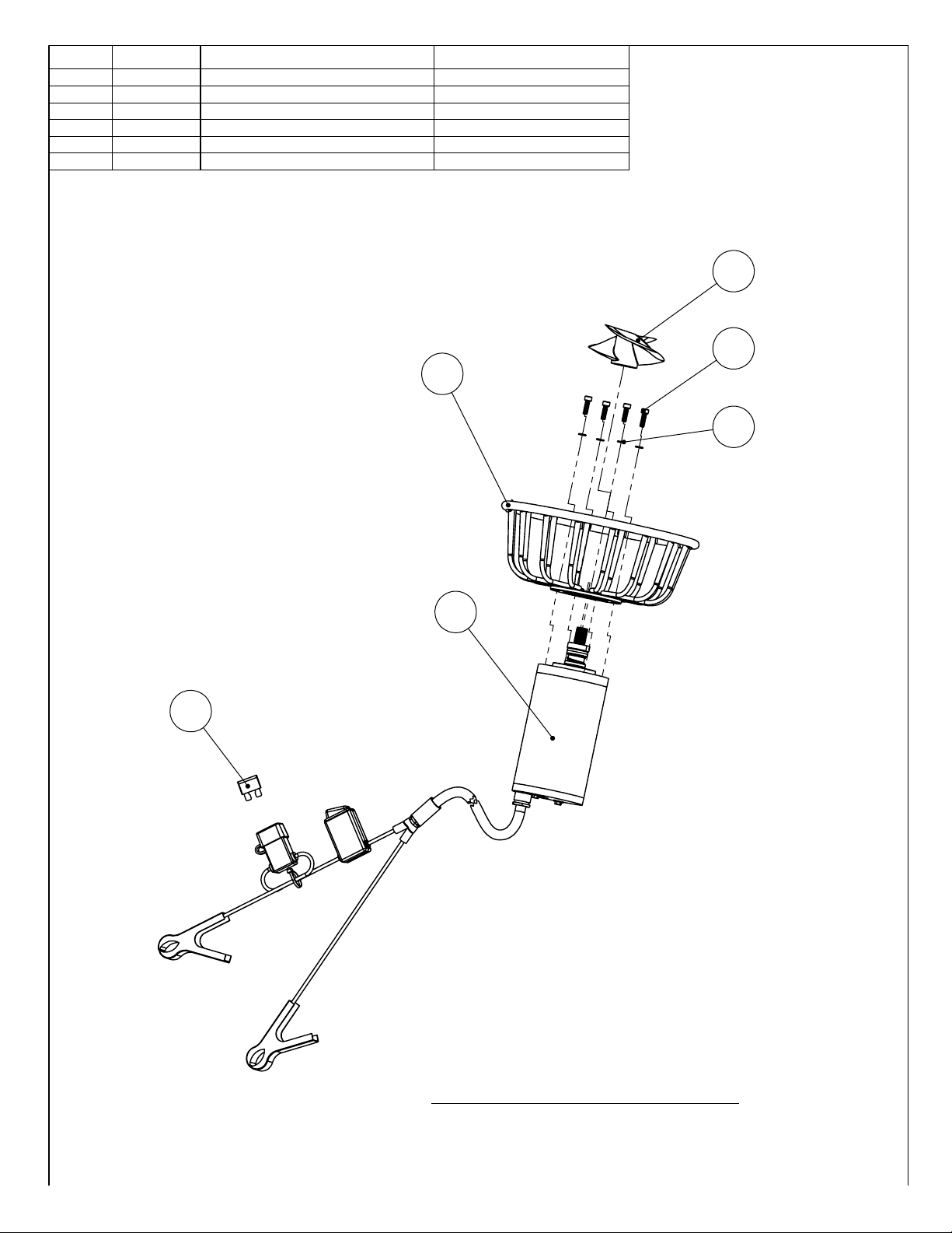
Your product is protected with a 25 Amp replaceable
fuse. If you have repeat, consistent trips of your fuse,
the equipment should be disconnected and removed
from the water. The power cord should be inspected for
damage and you should call a Kasco Marine distributor or
representative for further instructions.
OBSERVATION: Operating equipment should be observed
on a regular basis (daily, if possible) for any reduction
or variation in performance. If a change in performance
is observed, the equipment should be disconnected from
power and inspected for any material that may have
clogged the system or wrapped around the shaft of the
motor, especially plastic bags and shing line. Even
though Kasco Aerators are among the most clog-resistant
on the market, it is impossible to protect against all items
that can clog equipment and still maintain a ow of water.
These materials can be very damaging to the equipment
under continued operation and must be removed as soon
as possible. ALWAYS DISCONNECT POWER TO THE
UNIT BEFORE ATTEMPTING TO REMOVE CLOGS.
CLEANING: Equipment should be removed from the
water at least once per month to clean the exterior of the
system, especially the painted steel motor housing. The
motor housing is the surface that dissipates heat into the
water and any algae, calcium, etc. build-up will become an
insulator that blocks heat transfer. In most cases a power
washer will be sufcient if the unit and algae are still wet.
If corrosion of the painted surfaces exists, clean and repaint
with a good quality epoxy paint.
SEAL REPLACEMENT: This is a sealed motor assembly
and the seal will wear out over time (similar to brake pads
on a car). Replacement of the seal after three years may
add longevity to the operation of the motor, saving you the
cost of more expensive repairs.
Seal replacement and all other repair services should be
performed by Kasco Marine or a Kasco trained Authorized
Repair Center. Please contact your Kasco Marine, Inc.
distributor or representative for your nearest Authorized
Repair Center.
UNIT STORAGE: When storing units during the offseason,
it is important to check for any damage to your unit, or
corrosion of painted metal parts. If corrosion does exist,
simply clean the area and repaint with a good quality epoxy
paint. This will help ensure your unit gives you trouble free
service.
Troubleshooting Tips
Below are some helpful troubleshooting tips. If a problem
occurs, please double check the assembly and installation
instructions and required power to drive your unit. More
troubleshooting tips can be found at
www.kascomarine.com (Under the Helpful Info tab)
“My Aerator seems to run slowly.”
This can also be a symptom of several possible
problems. There could be an electrical problem where
the unit is not getting the proper voltage. This could also
indicate a problem with the motor of the unit, which needs
to be looked at by an Authorized Repair Center. Check that
the unit is receiving the proper voltage, and, if so, contact
Kasco for further steps.
Note: If the Aerator has been stored or exposed to cold for
an extended period without running, it may take a minute
for the prop to get to full speed once power is supplied.
“My Aerator ow seems to uctuate and/or be less than
usual.”
This can occur because of a few different reasons.
Most of the time, this symptom is caused from unit being
clogged with debris. A mat of weeds, many leaves, plastic
bags, etc. can clog up the unit and cause it to be starved of
water. If the unit does not have the proper amount of water,
the ow or pattern will uctuate up and down and look
sporadic. If you are seeing these symptoms, disconnect the
unit from power and clean away the debris that is clogging
up the prop guard. Another possibility if these symptoms
are noticed, is a chipped or damaged prop that is causing
the unit to wobble and not pump properly. When the unit is
disconnected from power, check the prop for damages and
replace if damage is found.
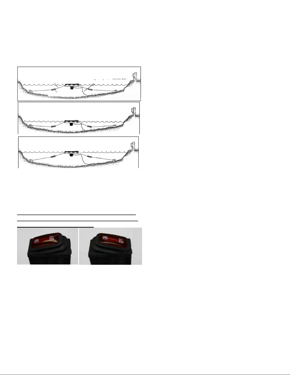
“My Aerator does not run”
This can occur because the user replaceable fuse
has blown. Check and replace if necessary.

11
800 Deere Rd.
Prescott, WI 54021
Phone: 715-262-4488 - Fax: 715-262-4487
www.KascoMarine.com [email protected]
Customer Repair Form
* Important Reminders *
• All repairs sent in MUST be accompanied by a copy of this completed sheet!
• Routine maintenance consists of keeping the unit clean and having the seals replaced every 3 years
depending on use.
• Address your Repair to Kasco Marine, Attn: Repairs (or to your Authorized Repair Center).
• Shipping to Kasco or an Authorized Repair Center is paid for by the customer.
• You must include the power cord and cage assembly with each unit sent in for repair to be considered for
warranty and for proper repair and shipping protection!
Today’s Date:___________________
Customer Information
Name: _________________ Phone Number: _____________________
Address: __________________________ Alternate Number: ___________________
City: ____________________ Email Address: ______________________
State: _____________________
Zip Code: ______________________
Unit Information:
Model # (Ex. 1812AF): ____________________
Serial # (Ex. 2101A181025): ____________________
Date Purchased: ________________________
Purchased From: _________________________
Earliest Date of Problem: _______________________
Description of Problem:
Comments:

12
Registration Information
Please register your fountain online at:
www.kascomarine.com
Also ll in the information below and keep for your records.
Model # (Ex. 1812AF)_______________________________
Serial # (Ex. 2101A181725)______________________________
Purchase Date:_____________________
Purchased From:___________________________________
Registration Date: ___________________________
Kasco Marine, Inc.
800 Deere Rd.
Prescott, WI 54021
Phone (715) 262-4488 • Fax (715) 262-4487
www.kascomarine.com • [email protected]
884814
Table of contents
Other Kasco Lawn And Garden Equipment manuals
Popular Lawn And Garden Equipment manuals by other brands

Land Pride
Land Pride RCR1860 Series Specifications & Capacities

Conrad
Conrad 621705 operating instructions

Blueprint Controllers
Blueprint Controllers EZGrow Timer quick guide

Zenport INDUSTRIES
Zenport INDUSTRIES LEP-858 user manual

Pond Pro
Pond Pro CAN-AIR KOI 1 owner's manual

FRAME IT ALL
FRAME IT ALL Topolski quick start guide

Toro
Toro 125-5180 installation instructions

Bosch
Bosch AHS 52 LI Original instructions

Agri-Fab
Agri-Fab Lawn Care Made Easy 45-03297 manual

Makita
Makita DUM166 instruction manual

Barko Hydraulics
Barko Hydraulics 640 Operator's manual

SAMSGAZEBOS
SAMSGAZEBOS 6' French Country Wood Garden Bridge Assembly instructions