Kasco VFX Series User manual

Owners Manual
VFX Series Aerators
2400VFX, 3400VFX, 4400VFX
3400HVFX, 4400HVFX
3020379
ANSI/UL 778: 2016
Ed.6+R:22Feb2017
CSA C22.2 #108: 2014 Ed.5
Kasco Marine, Inc.
800 Deere Rd.
Prescott, WI 54021
PH (715) 262-4488
www.kascomarine.com
Manual Number
884170
Rev. 7-2020

2
Important Safety Instructions. . . .
pg2
General Owner’s Instructions. . . .
pg2
Unit Specs. . . .
pg4
VX Pattern Sizes. . . .
pg4
2400VFX, 3400(H)VFX, 4400(H)VFX Parts Included. . . .
pg5
2400VFX, 3400(H)VFX, 4400(H)VFX Assembly. . . .
pg6
VFX Installation Instructions. . . .
pg8
Control Panel Installation. . . .
pg9
C-25 Timer Control Instructions. . . .
pg10
C85 / C95 non-metallic Control Panel Timer. . . .
pg11
2400, 3400, 4400 Parts Diagram. . . .
pg12
Maintenance Recommendations. . . .
pg13
Warranty Policy. . . .
pg14
Troubleshooting Tips. . . .
pg15
Customer Repair Form. . . .
pg17
Registration Information. . . .
pg18
THANKS
We at Kasco Marine, Inc. would like to both thank and congratulate you on your purchase of the VFX model aerator. We appreciate
you choosing Kasco and for your purchase. Your decision to purchase Kasco’s VFX model Aerator will not disappoint you. The VFX
model Aerator will be a great addition to your body of water. It will help improve the water quality by adding much needed oxygen and
circulation. It will also enhance the aesthetics of the pond or lake with a beautiful pattern. The lighting package (if purchased) will
illuminate your aerator for beauty at night. We thank you for choosing Kasco for your aerator needs and want you to be completely
satisfied with your purchase.
Important Safety Instructions
Please read and follow these extremely important safety and handling instructions for your Kasco equipment. Following these
instructions will help ensure your safety and the quality performance of your equipment.
•Under NO circumstances should anyone enter the water with the electrical equipment plugged in and/ or in operation. Kasco
equipment is ETL approved to UL and CSA standards for safety in water. However, it is NEVER recommended to enter the water
with the equipment in operation.
•Caution should be used when dealing with any electrical equipment with moving parts.
•NEVER run the unit out of water. It will damage the seals and create a dangerous situation for the operator.
•Extreme caution should be used around water, especially cold water, such as in Spring, Fall, and Winter, which poses a hazard in
and of itself.
•NEVER lift or drag the aerator by the power or light cord. If you need to pull the unit to the side of the pond, use the anchoring
ropes.
•Do not use waders in deep ponds/lakes or ponds/lakes with drop-offs, drastic slopes, or soft bottom material.
•Do not use boats that tip easily for aerator installation, such as a canoe, and follow all boating safety rules and regulations, including
wearing a PFD. (Personal Flotation Device)

•Single phase aerators are supplied with an internal grounding conductor and/or a grounding-type attachment plug. To reduce the
risk of electrical shock, be certain the aerator is properly connected to the
Kasco supplied control panel. (refer to the C-25,
C-85 & C-95 Control instructions)
•3 phase aerators (2.3VFX, 5.3VFX) require a startup test after wiring to ensure proper rotation of the propeller. If the propeller is
rotating in the opposite direction, the unit will not perform properly and internal damage to the unit may occur. (See 3 phase startup
procedure)
•Control panels must be installed a minimum of 5ft(3m in Canada) from the inside wall of the pond, unless separated from the body of
water by a fence wall, or other permanent barrier that will make the unit inaccessible to persons in the water.
•Control panels must be installed by a qualified electrician.
•Ground Fault Circuit Interrupters (GFCI) should be tested upon each installation and every month thereafter to ensure proper
operation.
General Owner’s Instructions
INSPECT THE SHIPMENT
Immediately inspect your Kasco Aerator shipment for any visible damages. Also cross reference the parts supplied with the Parts
Included sheet to check for shortages. Shortages should be reported immediately to your Kasco Marine distributor or representative
and damages reported to your carrier and Kasco Marine.
CAUTION
WARNING: Under NO circumstances should anyone enter the water with the unit in operation. Always operate the unit in the water
and keep people and objects clear of the propeller. Do not lift or pull the unit by the electrical cord. Always use extreme caution
around electrical equipment and water situations.
ASSEMBLY & INSTALLATION
Please see the proper Assembly and Installation Instructions enclosed in this manual. Each is specific for your model and size of
aerator. Note: Use a nylon tie to help keep the power cords for the unit and lights free of the propeller by tying each cord to either side
of the float. If you have a light kit, make sure that the unit cord is tied to one side of the float and the light cord to the other for balance.
Note: It is extremely important to test the GFI breaker in the control panel upon each installation/reinstallation of the unit to ensure
proper functioning.
WARRANTY
Kasco aerators are the result of over 35 years of design and engineering. Kasco products are built to withstand the toughest
conditions. Kasco Marine backs each VFX model aerator with either a 2 Year or 3 Year Warranty depending on the model. This
warranty covers any and all manufacturers defects within the warranty period from the date of purchase (See Warranty Section).
USE AND OPERATION
Kasco aerators are designed and engineered for continuous duty, such as on fish farms or other aquaculture applications, or on-
demand use, as needed in a recreational water feature. During flotation operation, the water is pulled from 360 degrees around the unit
and from below the unit. The water is pulled upward and thrust through the flotation collar into the air. Your Kasco Marine aerator is
ready for immediate use (after installation). Make sure to keep the motor housing clean from hard water deposits and/or algae. (See
Maintenance Recommendations.) It is extremely important that proper and sufficient voltage is supplied to the aerator motor. Unit
should be protected by a GFCI. Control panels must be installed by a qualified electrician. (See Installation instructions).
UNIT STORAGE
When storing units during the offseason, it is important to store them upside down if they are going to be sitting for long periods of time.
Units that sit upright on a shelf for many months, or even years have a greater likelihood of seals drying out. Storing upside down will
ensure oil is lubricating the seals and prevent drying.

4
Unit Specs
Model
Voltage
Amps
Lock rotor
amps
Control box connection
Aerator connection
single phase aerators
2400VFX
110-120
5.6
12
C-25 plug in
Plug into C-25
3400VFX
110-120
7.3
18
C-25 plug in
Plug into C-25
3400HVFX
208-240
3.7
9
Hardwire C-85
plug into or hardwire
C85
4400VFX
110-120
11.3
40
C-25 plug in
Plug into C-25
4400HVFX
208-240
5.7
20
Hardwire C-85
plug into or hardwire
C85
VX Pattern Sizes
NOTE: Pattern sizes listed are approximate. Variations in voltage caused by regional electrical differences or voltage drop due to long
power cords may result in reduced pattern sizes.
Model
Height
Width
2400VFX
5’
15’
3400VFX
5.5’
21’
3400HVFX
5.5’
21’
4400VFX
8’
26’
4400HVFX
8’
26’

Also Included:
•Cord in separate box (1) (depending on size of cord)
•Control Box (C-25 for 120V units in Float box or C-85 for 240V units in separate box) (1) (Not
Pictured)
TOOLS & SUPPLIES NEEDED
•Anchors or stakes for installing unit (2)
•# 2 Phillips head screw driver
•120V or 240V Electrical Supply near pond on a post with room for mounting the C-25 or C-85
•Two 12” pieces of 1” galvanized pipe for weighting ropes (optional)
•#10 x 1” long or longer screw(s) for mounting the C-25 (3) or C-85 (4)
•7/16” Socket and Ratchet
•7/16” Wrench
•11/32” wrench (for #8 fasteners)
#
Item
Part#
Qty
1
Aerator
1
2
Float
242001
1
3
1/4-20 x 3 1/2”
Phillips Pan
Head Screw
251210
4
4
1/4” split washers
840537
7
5
1/4” (3/4” OD) Flat
Washer
251300
10
6
1/4 -20 x 1-3/4” Hex
Head Bolt
475630
3
7
Bottom Screen
Section
361540
3
8
1/4”-20 Nut
840536
3
9
#8 nut
771034
6
10
#8 flat washer
361543
12
11
#8 lock washer
771033
6
12
#8 x 3/4” screw
361545
6
Not pictured
Mooring ropes
990700
2
cable ties
415038
9
2400VFX, 3400(H)VFX and 4400(H)VFX
Parts Included

6
5
3
4
5
9
10
10
11
12
6
5
5
4
8
2400VFX, 3400(H)VFX, 4400(H)VFX Assembly
1
.
Rest the float on
the 4 legs of the
housing.
Align power
cord with notch
Align bolt holes
with legs
. Lock washer goes
2
between bolt and
flat washer. Tighten
down in 4 places
3
. Turn over. Bring
bottom screen
sections together
4
. Tighten down in 6
places to hold the
screen together.
For quicker assembly:
Use cable tie instead
. Secure the bottom screen
5
to the float in 3 places.
Make sure cord is
sticking out of notch

7. If ready to install in the pond, go to Installation instructions. Light Kits can also be installed at
this time, go to Light kit instructions.
6
. Turn upright. Secure
power cord to rope hole
OR
With Strain Relief
Without Strain Relief

8
Use the ropes to position the aerator in the desired location
in the pond/lake. Anchor the ropes or secure them to the
shoreline so the ropes are free of slack, but not tight. To
prevent twisting of the unit due to torque, you should place
the anchor at least 3 feet from the float for each foot of depth
(Ex. A 6 foot deep pond would require an anchor 18 feet
horizontally from the float.)
VFX Installation Instructions
Alternate Installation Instructions:
In ponds where the water level fluctuates significantly, you
may need to suspend a small weight (12” of 1” galvanize
pipe works well) at the mid-point of the rope to take up
any slack as the water level drops. The weight should be
light enough so the aerator can rise as the water level
rises. This can also help hide ropes by sinking them
further below the surface.

9
1. Inspect the panel for any damage and any components that may have loosened during shipping. Control panel must be
installed a minimum of 5ft (3m in Canada) from the inside wall of the pond, unless separated from the body of water by a
fence wall, or other permanent barrier that will make the unit inaccessible to persons in the water. Install the control panel
to a post structure, side of a building, or other reliable means. This structure must support the panel and prevent
movement/flexing of the panel. Use #10 x 1” or longer screws in the mounting points of the control panel to secure to the
post structure. NOTE: The control panel must be hung upright to be waterproof. It is also advised to mount the panel out of
direct sunlight if possible by mounting the panel in a North direction. Also, mount the panel above the potential flood plain
to prevent water entry during a possible flood event.
2. Set Timer in the control panel to desired ON and OFF times per the Instructions for each specific timer.
3. Follow all local and national electrical codes for this installation and Consult a qualified electrician or service
person if needed.
a. (For 120V Installations) Plug the aerator cord into the C-25 outlet labeled “UNIT”. If lights are included, plug the
Transformer cord into the C-25 outlet labeled “LIGHT”. Now you are ready to plug the C-25 into the 120V power
supply on the post and ENJOY YOUR NEW KASCO AERATOR!
b. (For 240V Installations –3400H, 4400H) All electrical connections to this panel must be made with proper strain
relief cord grip fittings or with conduit connections as required by local and national electric codes. The bottom of
the enclosure is reserved for field installation of these connections.
i. C85 / C95 non-metallic control panel: Incoming power connection: (Power feed) This control panel
requires a 240V or 208V - 4 wire service (L1, L2, N, & G) and must be fed with a power circuit protected
by a circuit breaker or a fused disconnect switch to provide circuit protection and a disconnection
means. C-85 panel requires at least a 30amp protected circuit feeding the panel. C-95 panel requires at
least a 40amp protected circuit feeding the panel. Connect your power feed as detailed in the wiring
diagram provided with this panel. L1 connects to Terminal #1 L2 connects to Terminal #2 N connects to
Terminal N G connects to Terminal GROUND - located on chassis plate Be sure to provide adequately
sized power conductors to prevent excessive voltage drop. Consult with your electrician to properly size
power feed conductors. Use copper conductors only. Aerator power cord connection: Your aerator
(pump) will be provided with a flexible power cord for connection to this control panel. If the power cord
has a plug, you will need to cut it off. The power cord conductors (black, white, green) will need to be
stripped back 1/2”. The outer black jacket should be stripped back at least 3inches. Follow the
connection diagram for terminating these three wires to the terminal blocks in the control panel. Black
connects to Terminal #4, White connects to Terminal #5, Green connects to Terminal G.
1. This control panel requires a hardwire connection for the light kit(s). To connect the light kit(s)
you will need to cut off the power cord plug that is molded to the light kit power cord. Strip back
the black outer jacket of the light kit power cord at least 3 inches to reveal the three internal
wires of the power cord. (black, white, and green conductors). These three wires will need to be
stripped back 1/2”. Follow the connection diagram for terminating these three wires to the
terminal blocks in the control panel. Light kit connections: Black connects to Terminal #6, White
connects to Terminal #7, Green connects to Terminal G.
4. Test the GFCB with the test button now and every 30 days. If lights are installed, they can now be installed per
Instructions included with the lights. Once completed, power can be restored to the panel. Record the following data while
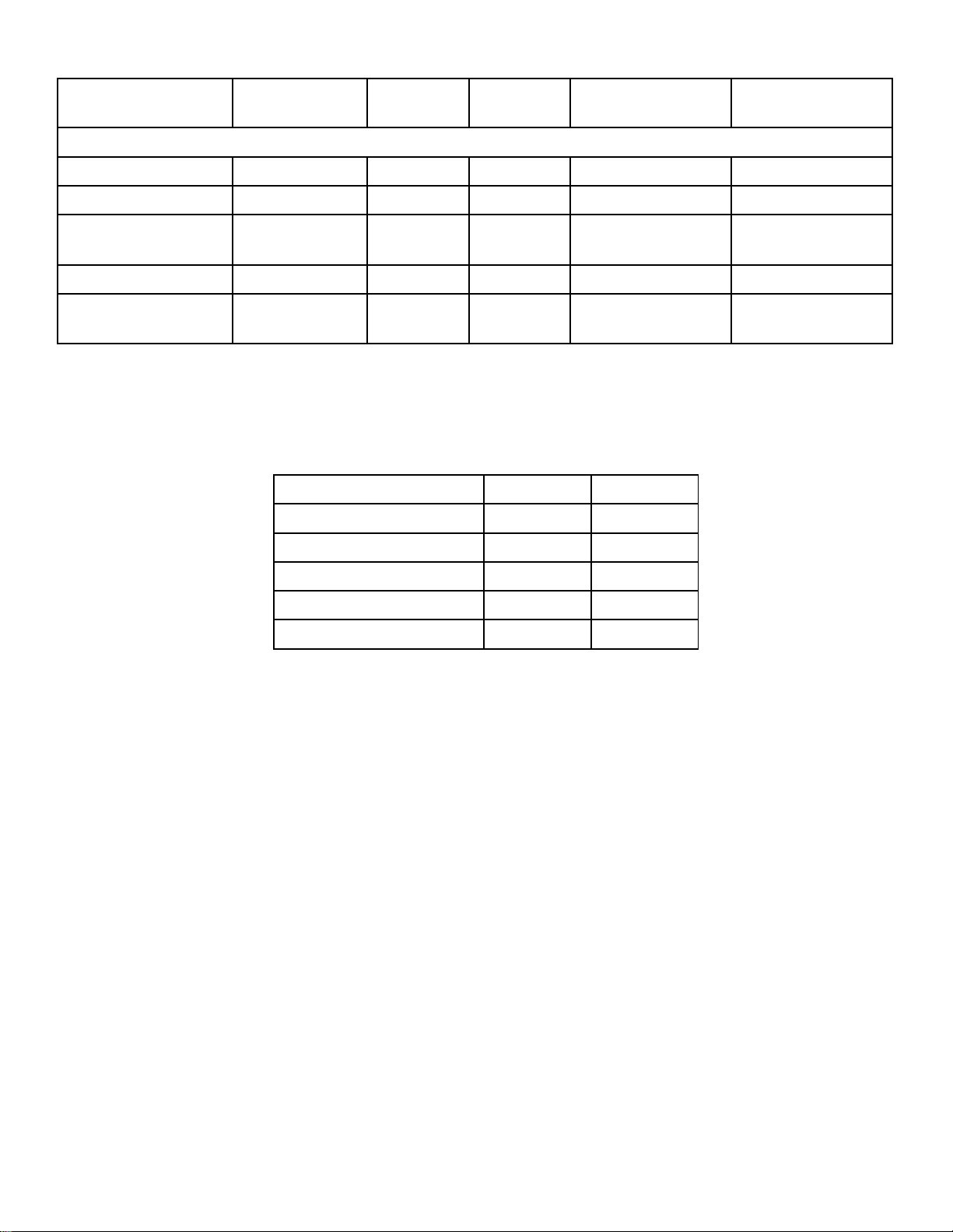
the Aerator is operating in the water under load:
Voltage:
L1-L2 ________
L1-N _________
L2-N _________
Amperage:
L1 __________
L2 __________
Date installed _____/_____/_____
Any unauthorized modifications to this control panel will void the UL listing and the Kasco warranty.
Control Panel Installation

10
C-25 Timer Control Instructions
Portable Timer with Ground Fault Interrupter
IMPORTANT
This portable timer is designed for CONTROLLING the connected equipment only. Unplug timer before
servicing the unit or the equipment it controls. For maximum protection against electrical shock hazard,
perform test procedure on G.F.C.I. at least once a month. Mount at least 5 ft. from open water.
G.F.C.I. TEST PROCEDURE
The G.F.C.I. should be checked every month to make sure that it is operating properly. Just follow the
simple instructions below. It is recommended to maintain a maintenance diary of your monthly safety
check.
1. Push TEST button, RESET button should pop out from inner surface. This should result in power being OFF at the
outlet protected by the G.F.C.I. Verify by plugging a test lamp into the outlet. Be sure the timer is in the ON position.
2. If the G.F.C.I. tests okay, restore power by pushing the RESET button back in. THE RESET BUTTON MUST BE
PUSHED FIRMLY AND FULLY INTO PLACE UNTIL IT LOCKS AND RE-MAINS DEPRESSED AFTER
PRESSURE HAS BEEN REMOVED.
DANGER: IF RESET BUTTON DOES NOT POP OUT, IF TEST LAMP REMAINS LIT WHEN RESET BUTTON DOES POP OUT, OR IF
THE G.F.C.I. FAILS TO RESET PROPERLY, DO NOT USE TIMER! CONTACT A QUALIFIED SERVICE TECHNICIAN!
Failure to use the C-25 with Kasco Fountains will void the warranty and cause the Fountain to not be listed to UL and CSA standards via
ETL.
UNDER NO CIRCUMSTANCES SHOULD ANYONE ENTER THE WATER WHEN A UNIT IS IN OPERATION!
TIMER-OPERATION INSTRUCTIONS
C-25 Control Box will turn the aerator/fountain ON & OFF with the TIMER. Kasco lights will turn ON with the PHOTO EYE and OFF
with TIMER. C-25 Control Box is to be used with Kasco Approved Lights ONLY!
•See Control panel label for instructions to set the timer
•Plug aerator/fountain cord into the RIGHT hand outlet (labeled UNIT).
•Plug transformer light cord into LEFT hand outlet (labeled LIGHT).

11
C85 / C95 non-metallic Control Panel Timer
TIME CLOCK SETTING
To set the current time, turn the inner dial clockwise. Do not set the time by rotating “outer” dial. Turn the minute hand or small
plastic inner dial clockwise until the time of day on the outer dial is aligned with the triangle marker on the inner dial (two o’clock
position). Example for 10:00 AM: Turn the minute hand clockwise until 10:00 AM is aligned with the triangle on the inner dial. The
hour and the minute dial will show exactly 10:00.
PROGRAMMING
The 24-hour dial has quarter-hour divisions and AM/PM indications. The time switch is programmed by pushing the captive
trippers to the outer ring position for the entire period that the aerator is to be turned “ON,” i.e. 15min for each tripper on the 24-
hour dial. When the tripper is pushed to the inside, the switch is in the “OFF” position.
PROGRAMMING WITH MANUAL OVERRIDE SWITCH
Your Timer may have a 3-way manual switch or a 2-way manual switch.
AUTOMATIC MODE In order to operate the time clock in the automatic mode, the manual switch must be in the
automatic postion- see diagram.
MANUAL MODE For the 3-way switch, with the manual override switch in the lower position, marked “O”, the time clock
output will remain Permanently OFF. In the upper position, marked “I”, the time clock output will remain permanently ON. For the
2-way switch, with the manual override switch in the lower position, marked “ON” the time clock output will remain permanently
ON.
Triangle marker
Captive trippers (in
the on position)

12

13
Maintenance Recommendations
** Under No Circumstances should anyone enter the water while
a aerator is operating. ** ** Please keep the original box for
maintenance shipping. **
The following maintenance procedures can be utilized to ensure
many years of quality performance from your Kasco aerator and
reduce the need for more costly repair work.
PROPER INSTALLATION: Proper installation of Kasco
equipment will include a power source with ground fault
interruption (GFI). For aerator models, the C-25 control (120V)
or C-85 (240/208V) included with the unit have built-in ground
fault interruption that is sufficient. Ground fault interrupters are a
safety feature that can also alert you to electrical leaks in the
equipment. It is extremely important to test the GFI upon
installation, each reinstallation, and monthly thereafter to ensure
proper operation. If you have repeat, consistent trips on your
ground fault, the equipment should be disconnected and
removed from the water. The power cord should be inspected
for damage and you should call Kasco Marine at 715262-4488
for further instructions or email Kasco at
returns@kascomarine.com.
OBSERVATION: Operating equipment should be
observed on a regular basis (daily, if possible) for any reduction or
variation in performance. If a change in performance is observed,
the equipment should be disconnected from power and inspected
for any material that may have clogged the system or wrapped
around the shaft of the motor, especially plastic bags and fishing
line. Even though Kasco Aerators and aerators are among the
most clog-resistant on the market, it is impossible to protect
against all items that can clog equipment and still maintain a flow
of water. These materials can be very damaging to the
equipment under continued operation and must be removed as
soon as possible. ALWAYS UNPLUG THE UNIT BEFORE
ATTEMPTING TO REMOVE CLOGS.
WINTER STORAGE: In regions where there is significant
freezing in the wintertime, the aerators should be removed from
the water to protect them from the expansion pressure of the ice.
In many areas, aerators will keep some amount of ice open
through the winter.
However, when the water is thrust into the air, it is exposed to the
colder air temperatures longer and can actually make ice thicker
on the pond/lake. Storage over winter is best in a location that is
out of the sun and cool, but above 32OF. When storing units
during the offseason, it is important to store them upside down if
they are going to be sitting for long periods of time. Units that sit
upright on a shelf for many months, or even years have a greater
likelihood of seals drying out. Storing upside down will ensure oil
is lubricating the seals and prevent drying.
CLEANING: Aerators should be removed from the water at least
once per year (at the end of the season in cold climates) to clean
the exterior of the system, especially the stainless steel motor
housing (can). The motor housing is the surface that dissipates
heat into the water and any algae, calcium, etc. build-up will
become an insulator that blocks heat transfer. In warmer regions
it is recommended that the motor is removed and cleaned at least
two to three times per year depending on conditions. In most
cases a power washer will be sufficient if the unit and algae are
still wet.
SEAL AND OIL REPLACEMENT: This is a sealed motor
assembly and seals will wear out over time (similar to brake pads
on a car). Replacement of the seals and a change of oil after
three years may add longevity to the operation of the motor,
saving you the cost of more expensive repairs. In warmer
climates where the aerator runs most or all of the year, it is a
good idea to replace seals more regularly than you would need
to in colder climates where the unit is removed from the water for
several months.
ZINC ANODE: A Sacrificial Zinc Anode is supplied on the shaft of
all VFX Model aerators for protection of the equipment from
corrosion and electrolysis. The zinc anode should be updated
(replaced) if reduced to half the original size or if white in color.
Corrosion from electrolysis is more commonly associated with
saltwater or brackish water, but as a matter of precaution, it is
important to periodically check the zinc anode in all installations
(at least every two to three months).
Seal replacement and all other repair services should be
performed by Kasco Marine or a Kasco trained Authorized Repair
Center. Any alterations or changes made to Kasco units by an
unauthorized source will void the warranty. This includes
tampering with the unit, power cord, and/or control box. Please
contact Kasco Marine, Inc. at 715-262-4488 for your nearest
Authorized Repair Center.

14
Warranty Policy
Warranty Period:
Models: 2400VFX, 3400(H)VFX, 4400(H)VFX
- 2 years
Models: 8400VFX, 2.3(H)VFX, 5.1VFX,
5.3(H)VFX - 3 years
Kasco® Marine, Inc. warrants this aerator to be free from defects
in material or workmanship (except for the ropes, power cord, and
propeller) under normal use and service. The Kasco Marine, Inc.
obligation under this warranty is limited to replacing or repairing
free of charge any defective part within the warranty period from
the date of shipment. Customer shall pay shipping charges for
returning the unit to Kasco or an Authorized Repair Center.
THIS WARRANTY IS IN LIEU OF ANY
OTHER WARRANTIES, EXPRESSED OR IMPLIED, AND ANY
OTHER OBLIGATION OR LIABILITY WHATEVER ON THE
PART OF KASCO
MARINE, INC. AND IN NO EVENT SHALL KASCO MARINE,
INC. BE LIABLE FOR ANY SPECIAL OR CONSEQUENTIAL
DAMAGES.
Warranty is void if:
•The aerator is not maintained properly according to the
Maintenance Recommendations supplied in this Owners
Manual.
•The aerator is returned for repair without the power cord or if
the unit, control box, or power cord are altered in any way
from original shipment. Cuts in the power cord are not
covered under warranty.
•The aerator is damaged by unauthorized tampering.
•The Sacrificial Zinc Anode around the propeller shaft shows
significant deterioration. (The Anode must be inspected
periodically and replaced if necessary.)
Warranty Claim Procedure:
The best method for establishing warranty period is by keeping
your original receipt. Also register the aerator online at:
www.kascomarine.com
Once the warranty coverage has been established, the unit may
be sent to any Kasco Authorized Repair Center for evaluation and
repair. Please call Kasco Marine at 715-262-4488 prior to
shipping.
Kasco Marine, Inc. 800
Deere Rd.
Prescott, WI 54021 Attn:
Repairs
Or call Kasco Marine at 715-262-4488 to locate your nearest
Authorized Repair Center. You can also email Kasco at
returns@kascomarine.com
Note: Only complete motor assemblies will be accepted for
warranty repair. The power cord and all other components must
be returned with the motor as originally assembled. Any missing
parts will be replaced at the customer’s expense and, if
determined to have caused the failure, could void the entire
warranty. Some parts are essential for structural support during
shipping and others, such as the power cord, are essential to
properly diagnose potential causes of failure. It is not necessary
to return the control box or float with the motor assembly.
Please include the Repair Form received from Kasco Marine or
your local distributor with the shipment. If no Repair Form is
available, include your name and physical address for return
delivery of the repaired unit and a daytime phone number and/or
e-mail address for correspondence regarding the warranty claim.
Any expedited shipping method for the return of the unit is at the
customer’s expense. Kasco Marine will return units repaired
under warranty at our expense via ground freight within the
continental United States.
Other Repairs:
Most failed equipment can be repaired at substantially lower costs
than replacement with new. Please ship according to the
instructions in the previous section. Again, it is best to call ahead
for a Return Authorization Number and/or Repair Form so we
know the repair is coming.
Kasco Marine does estimates on repairs at the request of the
customer. The request for estimate should be included in the
letter that accompanies the returned unit and must include a
daytime phone number and/or e-mail address. Estimate options
are as follows:
We will contact the customer with a total after the unit has been
evaluated, but before the work is performed. We will repair the
unit only if repair costs are under a stated dollar amount.
Example: “Please repair if total is under $150.00 before shipping
charges.”
All estimates that are rejected for repair will be destroyed unless
otherwise directed by the customer. If the customer would like the
unit returned, the unit will be restored as closely as possible to the
condition in which it was received and shipped at the customer’s
expense for shipping and handling charges.

15
Billing:
All non-warranty repairs will be returned to the customer prepaid
with Visa or Mastercard or shipped C.O.D. with C.O.D. charges
unless otherwise directed. Kasco Marine will contact for credit
card information upon completion of the estimate at the
customer’s request.
All other warranty and repair inquiries should be directed to Kasco
Marine, Inc. at 715-262-4488 or returns@kascomarine.com
Troubleshooting Tips
Below are some helpful troubleshooting tips. If a problem occurs,
please double check the assembly and installation instructions as
well as the instructions for the proper control panel. More
troubleshooting tips can be found at www.kascomarine.com
(under the technical tab)
“My Aerator trips the ground fault interrupter in the
C-25, C-85, or C-95.”
This is the most common symptom of several
possible problems. To correctly diagnose the problem, you will
need to collect more information. A Ground Fault Interrupter
(GFI) breaker that trips can in- dicate an electrical service
problem, water contamination in the unit and/or cord, bad breaker,
control box problems, motor problems, etc. Try to find out the
answers to these questions before you contact Kasco to narrow
down the problem.
•How long does it take to trip the breaker?
•Does it always take the same amount of time to trip?
•How many times has it tripped?
•Has there been any electrical problems in the area recently?
“My Aerator seems to run slowly.”
This can also be a symptom of several possible
problems. There could be an electrical problem where the unit is
not getting the proper voltage. This could also indicate a problem
with the motor of the unit, which needs to be looked at by an
Authorized Repair Center. Check that the unit is receiving the
proper voltage, and, if so, contact Kasco for further steps.
“My Aerator hums, but will not start. When I spin the prop with a
stick, it starts up.” (single phase units
only)
This indicated a problem with the Starting
Capacitor. Each Kasco aerator is equipped with a Starting
Capacitor to get the unit going when it is first plugged in. If it is
operating, but not spinning and can be started by spinning the
prop with a stick, the Starting capacitor needs to be replaced by
an Authorized Repair Center.
“My Aerator turns itself off and back on without the timer and
without tripping the GFI breaker.” (single phase units only)
Each Kasco aerator has a Thermal Overload built in that
will turn the unit off when it overheats. Once the unit has cooled
down, it will start back up. If you are noticing these symptoms,
the unit should be unplugged immediately because the Thermal
Overload will continue to turn on and off until it burns out and
damages the motor. The unit should be unplugged and taken out
of the water to find the cause of the problem. The problem could
be one of many, such as, low water levels, build-up on the unit to
prevent heat dissipation, something inhibiting the free rotation of
the shaft, etc. If something is caught in the unit or there is a build-
up of algae, calcium or organic matter on the unit, remove the
debris and, if caught early enough, the unit should be fine.
Contact a Kasco representative before restarting the unit.
“My Aerator flow seems to fluctuate and/or be less than usual.”
This can occur because of a few different reasons. Most
of the time, this symptom is caused from unit being clogged with
debris. A mat of weeds, many leaves, plastic bags, etc. can clog
up the unit and cause it to be starved of water. If the unit does not
have the proper amount of water, the flow or pattern will fluctuate
up and down and look sporadic. If you are seeing these
symptoms, unplug the unit and clean away the debris that is
clogging up the screen. Another possibility if these symptoms are
noticed, is a chipped or damaged prop that is causing the unit to
wobble and not pump properly. When the unit is unplugged,
check the prop for damages and replace if damage is found.
“The GFI breaker trips randomly and sporadically. Sometimes it
is a few hours of operation, other times it
can be days or weeks.”
This is referred to as a Nuisance Trip. This usually
occurs where the unit is installed a great distance from the initial
electric service on the property where the ground stake is placed.
It is caused by either induced current in the ground wire or a base
voltage difference due to soil pH levels. To resolve the problem,
contact an electrician and install a local grounding stake. This
may eliminate the induced current and any base voltage
differences. This problem can also be caused by a bad breaker
or receptacle or having unbalanced incoming voltage lines.

16

17
800 Deere Rd
Prescott, WI 54021
Phone: 715‐262‐4488 Fax: 715‐262‐4487
www.Kascomarine.com Sales@kascomarine.com
Repair Contact Form
❖Kasco requires all Repairs sent in MUST be accompanied by this form and marked to Repairs attention. (ex. Attn:
Repairs)
❖Repairs returned should include upper pump housing or wire basket for Aerators and De‐Icers. These parts
protect the motor during shipping.
❖Kasco is NOT responsible for shipping damage accrued in return shipment.
❖It is the responsibility of customer to ship and pay freight to Kasco.
❖Do not ship float or control panel with unit, unless otherwise instructed
❖A fee of $60 per hour will be assessed for cleaning excessively dirty units and float disassembly
❖Refer to the Owner’s manual for easy‐to‐follow troubleshooting rule out site issue.
Note: Contact Information Should be that of the person or company to contact for repair.
Company
First Name
Last Name
Address
City
State
Zip code
Phone #
Alternate Phone #
Email Address
Preferred method of contact (Circle)
Phone Email
Purchase order #
Additional notes for technician.
Submersible Pump Information (Complete if
sending unit)
Parts Included (For office use)
Light kit Information (complete if sending lights)
Model #
Model #
Unit
Serial #
Serial #
Cord
Cord Length:
Cord Length:
Light Kit
Purchased from:
Purchased From
Float
Purchase Date:
Purchase Date:
Control Panel

18
Registration Information
Fill in the information below and keep for your records.
Model # (Ex. 5.1VX)_______________________________
Serial # (Ex. 5101VX511725)______________________________
Purchase Date:_____________________
Purchased From:___________________________________
Registration Date: ___________________________
Other manuals for VFX Series
1
This manual suits for next models
5
Table of contents
Other Kasco Lawn And Garden Equipment manuals

Kasco
Kasco Robust-Aire Diffuser User manual

Kasco
Kasco Robust-Aire RA1-PM User manual

Kasco
Kasco 1812AF User manual

Kasco
Kasco 2400EVFX Manual

Kasco
Kasco 3.1EVFX Manual

Kasco
Kasco Robust-Aire User manual

Kasco
Kasco 2400EAF Manual

Kasco
Kasco VFX Series User manual

Kasco
Kasco 8400A Manual

Kasco
Kasco 8400EA Manual