Kasda KT101 User manual

KT101
Broadband IP Phone User Manual

IP Phone User Manual
2/ 42
Content
1Product Overview..................................................................................................................................................4
1.1 Introduction to IP Telephony....................................................................................................................4
1.2 Features .....................................................................................................................................................4
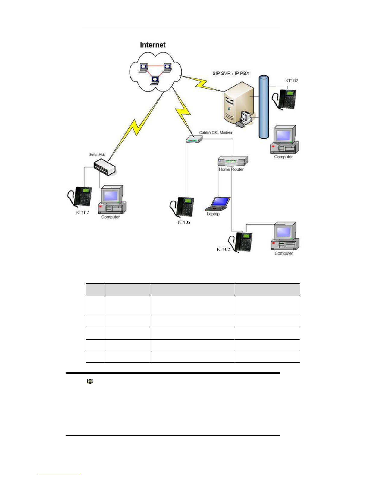
1.3 Intended Users and Situations..................................................................................................................5
1.4 Top View and Button Description..............................................................................................................6
2Installation................................................................................................................................................................8
2.1 Packing List..................................................................................................................................................8
2.2 Interfaces of Your KT101 ...........................................................................................................................8
2.3 Installation and Connection.......................................................................................................................8
3Configuration .........................................................................................................................................................10
3.1 Introduction ................................................................................................................................................10
3.2 LCD-based Configuration........................................................................................................................10
3.2.1 Configuring Network Parameters...........................................................................................11
3.2.2 Configuring Protocol Parameters.......................................................................................... 14
3.3 Web-based Configuration........................................................................................................................14
3.3.1 Logging into the Web Configuration Interface.................................................................... 15
3.3.2 Configuring Network Parameters.......................................................................................... 16
3.3.3 Configuring Protocol Parameters.......................................................................................... 22
3.3.4 Administering Your KT101..................................................................................................... 23
4Configuration Example.........................................................................................................................................25
4.1 Accessing Networks through PPPoE.....................................................................................................25
4.1.1 Scenario.................................................................................................................................... 25
4.1.2 Installing Hardware................................................................................................................. 25
4.1.3 Configuring Software.............................................................................................................. 25
4.2 Accessing Networks Using DHCP..........................................................................................................26
4.2.1 Scenario.................................................................................................................................... 26
4.2.2 Installing Hardware................................................................................................................. 26
4.2.3 Configuring Software.............................................................................................................. 26
5Operation................................................................................................................................................................26
5.1 Basic Operation.........................................................................................................................................26
5.1.1 Placing/Answering a Call....................................................................................................... 26
5.1.2 Redialing................................................................................................................................... 27
5.1.3 Holding On ............................................................................................................................... 27
5.1.4 Speed dialing........................................................................................................................... 27
5.2 Phone Book................................................................................................................................................27
5.2.1 Operating with Phone Book................................................................................................... 28
5.2.2 Operation Examples............................................................................................................... 29
5.3 Recent Calls...............................................................................................................................................29
5.4 Recorder.....................................................................................................................................................30
5.5 Voice Settings............................................................................................................................................31
5.5.1 Voice Setting—LCD-based Configuration........................................................................... 32
5.5.2 Voice Setting —Web-based Configuration.......................................................................... 33
5.6 Alarm Clock................................................................................................................................................34

IP Phone User Manual
3/ 42
5.7 Supplementary Service............................................................................................................................35
5.7.1 Call Hold on Music.................................................................................................................. 35
5.7.2 Call Wait ................................................................................................................................... 35
5.7.3 Unattended/Attended Call Transfer...................................................................................... 36
5.7.4 Call Forward............................................................................................................................. 36
5.7.5 Prefix Number.......................................................................................................................... 37
5.7.6 Hotline Calling.......................................................................................................................... 37
5.7.7 3-Way Conference.................................................................................................................. 37
5.7.8 Do Not Disturb......................................................................................................................... 37
5.7.9 Call Mute .................................................................................................................................. 38
5.8 Others.........................................................................................................................................................38
6Appendix A - Troubleshooting .............................................................................................................................40
7Appendix B - Technical Specifications...............................................................................................................41
7.1 Software Specifications............................................................................................................................41
7.2 Hardware Specifications ..........................................................................................................................41

IP Phone User Manual
4/ 42
1 Product Overview
1.1 Introduction to IP Telephony
Internet Protocol (IP) has its implementations in voice field. An example of this is the IP
phone system, which carries voice via IP packets and can be implemented in IP
networks, such as Intranets, WANs, and the Internet. Because the voice data is
transmitted over the IP network, IP telephony features lower cost and respectable
quality, especially for long distance calls. The KT101 is a SIP-based phone newly
launched by Technologies. Each KT101 has two Ethernet interfaces: the LAN interface
for access to a LAN or the Internet and the PC interface for connection to a PC. The
built-in network address translation (NAT) and dynamic host configuration protocol
(DHCP) functions enable a KT101 and the PCs connect to it to share the same
connection to a LAN or the Internet.
The comprehensive software features and superior voice coding performance enable
KT101 to provide you with cost-effective voice communication solutions. The LCD-and
Web-based configuration allows you to configure KT101 easily and conveniently.
1.2 Features
Dual-Mode Phones (Optional)
IP phone mode and PSTN phone mode
Working mode can be switched
Select default calling mode
Networks
Multiple ways to access the Internet, such as asymmetric digital subscriber line
(ADSL), digital data network (DDN), cable Modem, LAN, and WAN
Two Ethernet interfaces (RJ-45), which are 10/100 Mbps autosensing and support
MDI/MDIX
NAT and Bridge route forwarding
DHCP client/ server
DMZ and static port mapping
Supports QoS via 802.1p/Q ensuring the reliable VoIP service in multi-service
environment
VoIP Services
Compatible with domestic and foreign common softswitch platforms, including ZTE,
Huawei, SONUS, Cisco, Lucent, Nortel, Siemens, UT Starcom, etc.
Multi-Users registration with SIP,MGCP or H.323

IP Phone User Manual
5/ 42
Supplementary Services-Call transfer(Blind transfer andAttended transfer), Call
forward (Unconditional, When busy, When no answer),Call wait, Call hold, Call
pickup, Multi-way conference, DnD, Call block, etc
Primary and backup server connection switching
Firmware upgrading automatically
Basic Functions
functions such as redial, and mute
Automatic vocal answering
Caller ID
Hands-free mode, adjustable volume, and multiple ringing tones
Simple and flexible configuration through LCD, web and ManageCenter
Plug and play (PnP), identical to legacy phones on placing and answering a call
Voice quality almost the same as that of a legacy phone
Ring files select and upload
Phone book
Call history
1.3 Intended Users and Situations
IP telephony is an idea choice for enterprises and individuals that place lots of long
distance calls. It has wide varieties of users, such as:
•Carriers and Internet telephony service providers (ITSP)
•Large companies, for placing long distance calls and interior communications
•Small-and medium-sized enterprises involved in international businesses, such as
travel agencies
•Foreign/joint ventures, foreign offices, and agents
•Hotels (in guest rooms, business centers, or for renting)
•Governmental agencies that deal with foreign affairs, international trade and
exchanges
•Colleges and science research organizations that have international collaborations.
•IP phone supermarkets, bars
•Individuals and households that need to keep close contact with friends or family
members that are traveling or living in other cities or abroad
•Businessmen that travel a lot
•Other broadband subscribers

IP Phone User Manual
6/ 42
1.4 Top View and Button Description
Figure 1-1 Top view of KT101
Table 1-1 and Table 1-2 describe the buttons of KT101.
Table 1-1 Button Description —function buttons
Press…
To…
Enter the main menu for the LCD-based configuration in
standby mode.
Enter the submenu of the current selected menu item. Confirm
and save the changes when editing parameters.
Increase the volume of the speaker (or the ring) in standby
mode. Increase the output volume of your KT101 during a call.
Move one line up when in LCD-based configuration. Move the
cursor left one character when editing a parameter.
Decrease the volume of the speaker (or the ring) in standby
mode Decrease the output volume of your KT101 during a call.
Move one line down when in LCD-based configuration. Move
the cursor right one character when editing a parameter.
Return to the upper level menu. Cancel changes just made
when editing a parameter.
Delete a character when editing a parameter.

IP Phone User Manual
7/ 42
Enter the phone book menu when the handset is on-hook,
where you can view and set contact entries.
Do not Disturb button in standby mode. The coming call will be
refused after enable the DND.
Mute the call during the call conversation.
The conference button, operation detail refer to ―5.7.7 3-Way
Conference‖
Enable microphone connection (Please refer to the real phone
specification).
Switch to make a PSTN call when pickup the phone.(only used
for dual-mode phone ,please refer to the real phone
specification)
FLASH
Enable line toggling during call waiting between 2 concurrent
calls or other service.
HOLD
Toggle Hold mode when during a call.
REDIAL
Call a dialed number. Call the last dialed number after picking
up the handset.
HANDFREE
Toggle between hands-free and normal modes.
Standby mode means that the telephone is ready for use and no call is active.
Table 1-2 Button Description —character buttons
Button
Corresponding
character
Button
Corresponding character
1 . , [ ] <>? and space
6 m n o M N O
2 a b c A B C
7 p q r s P Q R S
3 d e f D E F
8 t u v T U V
4 g h i G H I
9 w x y z W X Y Z
5 j k l J K L
0 @ /_ -+ $ %
*
#
Note:
Pressing a character button repeatedly can display its corresponding characters
one after another at the cursor. For example, by pressing <5> twice, you can
display the character j at the cursor, which will be selected after two seconds of
pause.
The function of IP/PSTN and Message button is not available.

IP Phone User Manual
8/ 42
2 Installation
2.1 Packing List
•Unpack the package carefully and check the following items:
•One IP phone set kit (a phone base, a handset, and a handset cord)
•One dedicated power adapter
•One Ethernet cable
•One CD containing the user manual
•If anything is broken or missing, contact your agent for help.
2.2 Interfaces of Your KT101
Your KT101 uses standard autosensing 10/100 Mbps Ethernet
interfaces (RJ-45) for connecting PCs through LANs, broadband
Ethernet, ADSL or cable Modem.
2.3 Installation and Connection
Follow these steps to connect your KT101:
1) Connect the handset to the base: Plug one end of the handset
cord to the port on the left side (top view) of the base and the
other end to the corresponding port on the handset.
2) Connect your KT101 to a network device: Connect one end of an
Ethernet cable to the LAN interface on the rear of the base, and
the other end to an Ethernet switch or other Ethernet access
device.
3) Connect your KT101 to a PC: Connect one end of another
network cable to the network adapter on the PC, the other end
to the PC interface on the rear of the base.
4) Power your KT101 on: Insert the output end of the power
adapter to the power socket on the rear of the base, and the
other end to the wall jack.

IP Phone User Manual
9/ 42
Figure 2-1 Connect your KT101
The following table describes the connections in the figure. Table 2-1
Description of the connections
No.
Connect…
To…
With…
1
LAN interface
The Ethernet interface of an
ADSL Modem or a switch
Straight-through cable
2
PC interface
The network interface on a
PC
Straight-through cable
3
Power socket
Wall jack
Power adapter
4
LINE interface
PSTN PBX or PABX
PSTN line
5
Microphone
Microphone handset
Microphone line
Note:
When powered on, your KT101 initializes the settings automatically and displays
information such as ―Decompressing…‖, ―Init Network…‖, and ―Current version‖.
After installing your KT101, you must perform network and protocol configurations to
make it register with the carrier’s server. Otherwise, the LCD displays
―Connecting…‖ and no dial tone can be heard when you pick up the handset.

IP Phone User Manual
10 / 42
LINE interface is used only for the phone which has PSTN function.
Microphone is used only the phone which has microphone connection port.
Caution:
Make sure that you plug the connectors of the handset cord in their ports completely
and securely.
3 Configuration
3.1 Introduction
Before you can use your KT101, you must configure its network connection type and
protocol parameters. To do so, you can use one of the following two ways: LCD-based
configuration and Web-based configuration.
LCD-based configuration: Configure parameters at prompts on the LCD by using the
buttons on your KT101. Web-based configuration: Configure on Web pages after logging
into the Web server built in your KT101 through a Web browser running on the PC
connected to your KT101.
You can select the one that best suits you.
Note:
Unless otherwise noted, the following configurations are only for demonstration purpose, other
than recommended settings. You can configure your KT101 by using the settings provided by
your carrier or administrator to suit your actual requirements.
3.2 LCD-based Configuration
The parameters of your KT101 are grouped by type in hierarchical menus displayed in the
LCD. You can use the buttons on your KT101 to perform menu operations and input
characters.
This section describes how to set by the LCD the network and protocol parameters
required for your KT101 to operate properly. Table 3-1 lists the basic button operations for
accomplishing all kinds of configurations.
Table 3-1 Basic button operations for LCD-based configuration

IP Phone User Manual
11 / 42
To…
Do the following…
Enter the main menu
Press <MENU>
Select an item from
the menu
Press <UP> or <DOWN> to move the prompting
arrow to the desired item Press the button for the
digit corresponding to the item
Enter a submenu
Press <OK>
Confirm your
selection or input
Press <OK>
Change a setting
Do the following to change the value of a
parameter:
1) Press <OK> to enter the editing mode of the
currently selected parameter.
2) Press buttons as needed to enter a new
value for the parameter, or press
<UP>/<DOWN> to select one from the
available values.
3) Press <OK> to confirm your changes, or
press <C> to discard them.
Note that:
1) For some parameters with optional values,
you can simply press <OK> to select one
without entering the editing mode.
2) When editing the value of a parameter, you
can move the cursor by pressing
<UP>/<DOWN>, or delete a character by
pressing <DEL>.
Return to the upper
level menu
Press <C>
Exit the configuration
interface
Press <C> repeatedly until the LCD displays ‖IP
Phone…‖
3.2.1Configuring Network Parameters
From the [Networks] menu, you can configure the network connection type, the forwarding
mode, DMZ, static port mapping, and so on. This section describes the hierarchy of the
[Networks] menu and the procedures for you to set the network connection type and
forwarding mode in different scenarios. These configurations are required for your KT101
and the PC to access the LAN or Internet. ADSL network mode means PPPoE here.
I. Hierarchy of the network configuration menu
Table 3-2 Hierarchy of the network configuration menu
Menu/item/value
Description
External
NIC
IP Mode
User
Specify
Static address
mode
Use the [IP Mode] menu to specify
the way for your KT101 to obtain the
IP address of the LAN interface.
DHCP
DHCP mode
PPPoE
PPPoE mode
IPAddress:
IP address of
the LAN
interface
These items are available only when
you set the IP Mode argument to
User Specify.

IP Phone User Manual
12 / 42
Subnet Mask:
Subnet mask of
the LAN
interface
Gateway
Default
gateway
PPPoE Name
PPPoE user
name
These items are available only when
you set the IP Mode argument to
PPPoE.
PPPoE Password
PPPoE
password
MAC Address
MAC address burned into the LAN interface, which you
cannot change.
Forward
Mode
Disable
Use the [Forward Mode] menu to set the forwarding
mode.
NAT
Bridge
Internal
NIC
IPAddress
IP address of the PC interface, which defaults to
192.168.254.1.
Subnet Mask
Subnet mask of the PC interface, which defaults to
255.255.255.0.
MAC Address
MAC address burned into the PC interface, which you
cannot change.
Default DNS
Use this item to set the IP address of the default DNS
server.
VLAN
VLAN ID
Use the [VLAN] menu to enable or disable the VLAN
tagging function. Refer to Table 3-1 for instructions of
basic button operations and section 3.3.2.III.
―Configuring VLAN‖ or the meanings of the settings.
Priority
Tag
Enable
Yes
No
Access PWD
Use this item to set a password for your KT101.
DMZ
Use the [DMZ] and [Static Portmap] menus to set DMZ
and static port mapping. Refer to Table 3-1 for
instructions of basic button operations and section
3.3.2.IV. ―Configuring DMZ and static port mapping‖for
the meanings of the settings.
Static Portmap
II. Configuring the network connection type
Your KT101 supports three network connection types: DHCP, PPPoE, and static address,
which correspond to the DHCP, PPPoE, and User Specify settings in the [IP Mode] menu
respectively. The IP Mode argument defaults to DHCP, which means that your KT101
obtains an IP address from a DHCP server by default.
Before configuring the network connection type, consult your carrier or administrator for
related information such as:
•The PPPoE user name and password (for the PPPoE mode)
•The IP address, subnet mask of your KT101, and the IP address of the default
gateway (for the User Specify mode)
•As DHCP is the default network connection type for your KT101, no configuration is

IP Phone User Manual
13 / 42
needed for your KT101 to operate in DHCP mode.
Follow these steps to configure the network connection type (refer to Table 3-1 for basic
button operations):
1) Enter the main menu.
2) Select [Networks] and confirm to enter its submenu.
3) At the prompt of ―Type Password:‖, enter the password ―285#”and confirm it.
4) Select [External NIC] and confirm, and then navigate to the IP Mode argument.
5) Set the IP Mode argument to PPPoE or User Specify.
6) Set other related parameters:
•For static address mode: navigate to IP Address, Subnet Mask, and Gateway to
specify the IP address and subnet mask of the LAN interface and the IP address of the
default gateway.
•For PPPoE mode: navigate to PPPoE Name and PPPoE Password to specify the
PPPoE user name and password.
7) Exit the configuration interface. When you exit the configuration interface, your KT101 will
restart to have the new settings take effect.
III. Configuring the forwarding mode
For a PC to access the LAN or Internet through your KT101, you must also configure the
forwarding mode of your KT101.The forwarding mode dictates how data is forwarded
between the LAN interface and the PC interface of your KT101, that is, the way for the PC
connected to your KT101 to obtain its IP address.
As shown in Table 3-2, the value of the Forward Mode argument can be Bridge (the
default), NAT, and Disable, which are described as follows:
•Bridge: Transparent bridge mode. In this mode, the PC interface of your KT101
functions as a Layer 2 switching port, and the LAN interface functions as a upstream
port. The PC connected to your KT101 accesses the LAN or the Internet in the same
way as your KT101. This mode is recommended for users who employ DHCP to
access a network.
•NAT: Network address translation (NAT) mode: In this mode, NAT and the built-in
DHCP server are enabled on your KT101. Your KT101 functions as a gateway with the
PC interface connected to the local network and the LAN interface connected to the
external network. For the PC connected to your KT101 to share the same connection
as your KT101 to access the LAN or the Internet, you only need to specify the PC to
obtain an IP address automatically. This mode is recommended for users who employ
PPPoE to access a network.
•Disable: In this mode, the PC interface of your KT101 is disabled, and the PC cannot
access the LAN or the Internet through your KT101, neither can it access the built-in
Web configuration pages of your KT101.
Follow these steps to configure the forwarding mode (refer to Table 3-1 for basic button
operations):
1) Enter the main menu.
2) Select [Networks] and confirm to enter its submenu.
3) When the LCD displays ―Type Password:‖, enter the password ―285#‖.

IP Phone User Manual
14 / 42
4) Navigate to the [Forward Mode] item.
5) Set the Forward Mode argument to NAT, Bridge, or Disable, and confirm the
setting.
6) Exit the configuration interface.
3.2.2Configuring Protocol Parameters
Protocol configuration refers to settings of VoIP, which enable your KT101 to register with
the servers of your carrier. Before performing protocol configuration, consult your carrier for
the required protocol parameters.
Follow these steps to perform protocol configuration (Refer to Table 3-1 for basic button
operations.)
1) Enter the main menu.
2) Enter **# by pressing the corresponding buttons. At the prompt of ―Type Password:‖,
enter the password ―582#‖and confirm it.
3) Scroll up or down, you can see the items described in Table 3-3.
Table 3-3 Protocol configuration menu
Item
Description
User ID
Phone number of your KT101
Auth ID
Authentication ID
Password
Authentication Password
Domain
Name
Domain name or IP address of the SIP
server
Default
Proxy
Proxy Server Address for SIP register
4) Set these parameters by using the settings provided by your carrier.
5) Exit the configuration interface. After you exit the configuration interface, your
KT101 initiates again for the new settings to take effect. The initiating process
finishes when ―IP Phone…‖appears in the LCD. If your KT101 succeeds in
registering with the server, the signal tone can be heard when you pick up the
handset.
Now, you have completed the network and protocol configurations and can use your
KT101 as you do with a legacy phone set.
3.3 Web-based Configuration
In addition to LCD-based configuration, you can also perform Web-based configuration
through the Web server built in your KT101. This section describes how to set network
and protocol parameters, and upgrade the software via Web pages.
•Note:
You can log into the Web configuration interface through the PC interface or the LAN
interface of your KT101. The former applies to any network connection type, and the latter

IP Phone User Manual
15 / 42
applies to the DHCP and static address modes. It is recommended that you use the PC
interface to log into the Web configuration interface.
To perform Web-based configuration, you need a PC with a browser (IE 6.0 or later
recommended) and TCP/IP installed. You also need to do the following to log into the
Web configuration interface via the PC.
•Connect the PC to your KT101 (refer to section 2.3 ―Installation and Connection‖ for
details).
•Set the forwarding mode of your KT101 to NAT (refer to section 3.2.1 III. .―Configuring
the forwarding mode‖ for details).
•Specify the PC to obtain an IP address automatically (refer to the online help
documentation of the operating system running on the PC) and restart the PC.
3.3.1 Logging into the Web Configuration Interface
Launch the browser on the PC and enter the IP address of the PC interface of your
KT101 (192.168.23.188 by default) in the address bar. The login page appears, as
shown in Figure 3-1.
Figure 3-1 Web configuration –the login page
Enter the password ―admin‖ of your KT101 in the [Password] text box and click
<Enter>. Click Networks, the main Web configuration page appears, as shown in
Figure 3-2.
Figure 3-2 Web configuration –the main page

IP Phone User Manual
16 / 42
The left part of the main page is the navigation list, where links to configuration pages
are located. Clicking on a link in the navigation list can have the corresponding
configuration page appear on the right part of the main page.
3.3.2 Configuring Network Parameters
On the [Networks] page, you can configure the network related parameters for your
KT101.Click <Networks> in the navigation list to bring up the network configuration
page, as shown in Figure 3-3. You can select the [LAN], [PC], [VLAN], or [DMZ] tab to
perform the corresponding configurations, which are described as follows:
I. Configuring the LAN interface
When you click <Networks> in the navigation list, the [LAN] tab (as shown in Figure
3-3) is brought up by default. The items in this tab are used to specify the way for your
KT101 to obtain an IP address for the LAN interface.
Figure 3-3 Web configuration –LAN setting
•Connection Type: Network connection type of your KT101. The three options in the
drop-down list, Static, DHCP, and PPPoE, stand for the following three network
connection type respectively: static address mode, DHCP mode, and PPPoE mode.
DHCP is selected by default. You can select an option as needed.
•Primary DNS: IP address of the default DNS server in the network where your KT101
resides.
•Secondary DNS: IP address of the secondary DNS server in the network where your
KT101 resides. If you select the Static option from the [Connection Type] drop-down
list, the items corresponding to the static address mode appear, as shown in Figure
3-4.

IP Phone User Manual
17 / 42
Figure 3-4 Web configuration –LAN setting - Static
For this mode, you must specify the IP address and subnet mask of the LAN interface,
and the default gateway manually.
•IP Address: IP address of the LAN interface on your KT101.
•Subnet Mask: Subnet mask of the LAN interface on your KT101.
•Gateway: IP address of the default gateway.
If you select the PPPoE option from the [Connection Type] drop-down list, the items
corresponding to the PPPoE mode appear, as shown in Figure 3-5.
Figure 3-5 Web configuration –LAN setting - PPPoE
For this mode, you must specify the PPPoE user name and password.
•PPPoE Name: PPPoE user name.
•PPPoE Password: PPPoE password.
Auto Down Time: Idle period of the LAN interface (the period during which no data
passes through the LAN interface), after which the PPPoE connection is terminated.
Figure 3-5 shows the available options, among which the disable option is selected by
default, which means the PPPoE connection will never be terminated regardless of the
period for which the LAN interface is idle. Other three settings, 1 minute, 4 minutes,

IP Phone User Manual
18 / 42
and 10 minutes, mean the PPPoE connection will be terminated after the LAN
interface is idle for 1, 4, or 10 minutes respectively.
Remember to click <OK> to save your changes upon completion. You can also click
<Cancel> to discard your changes.
After the changes are successfully saved, the [Result] page appears, as shown in
Figure 3-6.
Figure 3-6 Web configuration –Result
Click <here> to bring up the login page (as shown in Figure 3-1) again. You can
proceed with other configurations after logging in.
Note:
If the login page does not appear after you click <here>, click <Refresh> in the browser to
login to the Web server.
II. Configuring the PC interface
Click the [PC] tab. The [PC Setting] page appears (as shown in Figure 3-7), displaying
the items for specifying the parameters of the PC interface.
Figure 3-7 Web configuration –PC Setting
•Forward Mode: Forwarding mode of your KT101. For details about the forwarding
modes, refer to section 3.2.1 III. .―Configuring the forwarding mode‖. Available options
include NAT, Bridge, and Disable, among which Bridge is selected by default.
•IP Address: IP address of the PC interface, which defaults to 192.168.254.1.

IP Phone User Manual
19 / 42
•Subnet mask: Subnet mask of the PC interface, which defaults to 255.255.255.0.
•MAC Address: MAC address burned into the PC interface, which you cannot change.
Remember to click <OK> to save your changes upon completion. You can also click
<Cancel> to discard your changes.
Note:
Settings of IP address, subnet mask, and MAC address for the PC interface take effect
only when the forwarding mode is set to NAT.
III. Configuring VLAN
Click the [VLAN] tab. The [VLAN Setting] page appears (as shown in Figure 3-8),
displaying the items for specifying the VLAN parameters.
Figure 3-8 Web configuration –VLAN Setting
Your KT101 supports the use of VLAN tag, which can increase the transmission rate of
RTP voice packets. Supports from the network are required for this function to take
effect. Consult your carrier or administrator for related information.
Items in this page are described as follows:
•Enable Tag: Specifies whether to enable the VLAN tagging function. The default
setting is Disable, that is, the VLAN tagging function is disabled by default.
•VLAN ID: VLAN ID, which can be obtained from your carrier or administrator.
•Priority: Priority of the VLAN tags.
Remember to click <OK> to save your changes upon completion. You can also click
<Cancel> to discard your changes.
Caution:
Enable the VLAN tagging function only when you are sure that the network to which your

IP Phone User Manual
20 / 42
KT101 is connected supports this function. Otherwise, your KT101 may be unable to obtain
a network address, or you cannot place calls.
IV. Configuring DMZ and static port mapping
When operating in NAT mode, your KT101 denies requests initiated from external IP
networks. But some implementations require accessing the PC connected to the PC
interface of your KT101 from external networks to utilize the services provided by the
PC. In this case, you can satisfy the requirement by enabling static port mapping or
DMZ function.
Click the [DMZ] tab. The DMZ and static port map page appears (as shown in Figure
3-9), displaying items for setting the DMZ and static port mapping functions.
Note:
The configurations described below about DMZ and static port mapping are necessary only
when the forwarding mode is set to NAT.
Figure 3-9 Web configuration –DMZ and Static Port Map
1) Configuring DMZ
With the DMZ function enabled, you can specify a port number range. Packets
destined for the LAN interface of your KT101 with destination port numbers within
this range are forwarded to the corresponding ports of the host that is connected to
the PC interface of your KT101. (The host herein is referred to as a DMZ host.)
When you select Enable from the [DMZ Enable] drop-down list to enable the DMZ
function, the related configuration items appear, as shown in Figure 3-10.
Table of contents