manuals.online logo
Brands
  1. Home
  2. •
  3. Brands
  4. •
  5. KASTOR
  6. •
  7. Heater
  8. •
  9. KASTOR K-007 User manual

KASTOR K-007 User manual

8/07
SAUNA K-007_KL-16VEAUNA K-007_KL-16VE
Kastor OY. Tehtaankatu 5-7, 11710 RIIHIMÄKI, FINLAND
Phone +358 19 764360, Fax +358 19 721 883
E-mail: [email protected], Internet www.kastor.fi
Saunatec Inc.
Cokato, MN, USA
1-888-780-4427
[email protected]
Installation and operating instructions
We are grateful that you have chosen a KASTOR product for your fireplace. Fireplace hearts from
KASTOR are renowned for their high quality and long life. SAVE THESE INSTRUCTIONS!
After installation, these instructions must be given to the owner of the fireplace or to the person
responsible for the use of the fireplace.
Before installation read these instructions carefully, especially the sections ” SAFETY DISTANCES AND
FIRE SAFETY” and ”PREPARING THE FIREPLACE FOR INSTALLATION” on page 1.
Illustrations 9-13
4211-60 Kastor K-007, KL16VE 1 3/25/11
Rev. 1
8/07
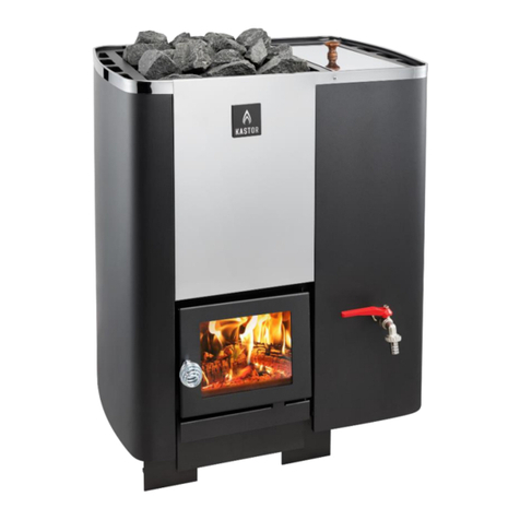
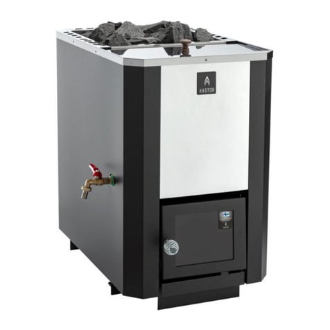
INSTRUCTIONS FOR WOOD-FUELLED KASTOR SAUNA HEATER
K-007, KL-16VE
1. IMPORTANT
Wood-fuelled sauna heaters are intended solely for heating saunas.
Keep this manual near the heater and consult it before taking any action.
Always comply with the instructions given in this manual and official building regulations
when installing and operating the heater. Non-compliance may result in injury and
damage!
The sauna heater may not be used for any other purpose, such as drying clothes, heating the
building during construction, curing meat, etc.
Never cover the heater with anything when it is being used or hot.
If the heater is exposed to moisture when not in use (e.g. in an unheated holiday home), always
check it for corrosion damage before use.
Before lighting the fire, make sure that the chimney has good draught and is intact.
A Kastor heater is a heating device that produces heat by means of heat storage, air circulation and
thermal radiation. Therefore its surfaces, lid and water tank knob and, in particular, stones
become very hot. Take care not you burn yourself.
A maritime climate may reduce the service life of the sauna heater. Never allow the heater to
come into contact with salt water which must not be used for producing steam. Please note that
water in wells near the sea may contain salts.
Sauna heater models with water tanks heat water to the boiling point. Boiling water and steam cause
burns when in contact with skin. Do not handle scalding hot water in the vicinity of other
persons. Great caution must also be exercised when running water out of the tap, since it
can overheat beyond the boiling point in certain circumstances. In such cases, a strong bump
with the cover or the scoop can cause the water to boil over abruptly.
2. INSTALLATION
2.1. PREPARATIONS
xPlace the sauna heater (without stones and water tank, or with the water tank filled with water, if
applicable) on a non-combustible base out of doors.
xRemove any labels, stickers and plastic sheeting from the heater before lighting the fire.
xA U.S. 6” Stove pipe adaptor has been supplied for ease of installation of chimney.
xInstall the exit flue pipe supplied with the heater in the rearmost flue pipe hole at the top of the heater
or in the hole in the heater’s back wall.
xCover the other holes with the lids supplied with the heater, including the opening in the back of the
heater.
xMake sure that the fire grate and the air deflector (section 3.2) are in position.
xLight a fire in the heater and burn a couple of fire boxfuls of logs to get rid of "manufacturing odors".
Keep the fire going until the heater stops smouldering.
xEnsure efficient ventilation of the steam room when heating the sauna for the first few times using a
new heater.
2.2. HEATER STONES AND THEIR PLACEMENT
Use peridotite or olivine stones or darkish natural stones that measure more than 10 cm (4”) in
diameter. (N.B. Flat stones should be placed in a vertical position!) Wash the stones before
use. Fill the stone chamber up to the brim. Do not pack the stones too tightly or in a pile –
they should be placed in an "irregular" pattern” - this will leave enough air gaps between
stones. Check a couple of times per year that the stones are not eroded.
By selecting the stones with care, using different quantities and mixing different types, it is possible to
"fine-tune" the properties of the steam and adapt it to individual tastes. No universally applicable
instructions can be given because these factors vary from sauna to sauna - experiment freely to
find the right solution.
4211-60 Kastor K-007, KL16VE 2 3/25/11
Rev. 1
8/07
2.3. SAFETY DISTANCES AND SAFEGUARDS
Failure to observe safety distances causes a risk of fire!
Sauna heaters are classified as hot units with a maximum surface temperature of 350oC (662°F). The
minimum distance from the rear and the sides of the heater to any combustible material or
surface is 500 mm (20”); from the front of the heater 1,000 mm (40”), and from the top of the
heater 1,200 mm (48”).
A 50% reduction in the safety distances is achieved with a single protective sheet and a 75% reduction
with a double sheet. Such a sheet may consist of 1 mm (3/64”) thick metal sheet or 7 mm (9/32”)
thick fiber-reinforced cement board (no paper-faced or similar gypsum board). A ventilation gap
of 30 mm (1 ¼”) must be left between the wall and the protective sheeting. Additionally, the
sheeting must be clear of the floor and ceiling. With heaters fitted with a hot water tank, the safety
distance to combustible material on the side of the tank is 150 mm (6”). If the floor of the sauna in
front of the heater is made of combustible material, the area to be protected should extend 100
mm to both sides of the fire door and to a minimum distance of 400 mm (16”) forward. The
protective sheeting must consist of a metal sheet with a minimum thickness of 1 mm. See also
section 2.4.
A 50 mm (2”) clearance to a brick wall is required on the sides and in the rear of the heater.
The safety distances of the connecting pipes between the heater and the chimney are 1,000 mm (40”)
in the lateral direction and 1,200 mm (48”) in the vertical direction. Safety distances can be
reduced using similar protective sheeting as with the heater itself. The minimum safety distance
of Kastor chimneys to combustible materials is 100 mm (4”), provided that the insulated part of
the chimney extends down to a height of 400 mm (16”) below the ceiling.
If you are uncertain, consult the local building authorities.
Heaters with an extended fire door section may only be installed through a wall made of
incombustible material (brick, concrete, etc.). Then, the incombustible material must enclose
the extended fire door as shown in Fig. 5. If the floor in front of the fire door is made of
combustible material, the area to be protected should extend 100 mm (4”) to both sides of the fire
door and to a minimum distance of 400 mm (16”) forward. The protective sheeting must consist
of a metal sheet with a minimum thickness of 1 mm (3/64”). See also section 2.4.
2.4. INSTALLATION BASE
Install the sauna heater on a level, firm and stable fire-insulated base, The front feet of the heater
include openings for adjusting screws that can be used to level the heater on a sloping floor. The
screws are found in the accessory bag inside the heater. Insert the screws and level the heater.
The best base is made of cast concrete. Installation on a tiled floor is not recommended
because damp proof courses and tile adhesives contain materials sensitive to heat. Please note
that light-coloured wooden floors are easily soiled by the ash and other impurities associated with
wood-fired heaters.
With proper fire insulation, the heater can also be installed on a wooden floor. Acceptable insulation is
usually provided by a 60 mm (2 7/16”) thick cast concrete slab with a smooth finish and slight
forward slope (ensure moisture removal). The fire insulation on the floor must extend a distance
of 400 mm (16”) beyond the front of the heater, 250 mm (10”) on both sides and 250 mm (10”) in
the rear, or up to an insulated wall on the side and in the rear.
– Heaters with an extended fire door section
The floor of the steam room and the room in which the fire door is located must be at the same level.
Alternatively, the floor of the room with the fire door may be lower that that of the steam room but
never higher!
The heater, the extended fire door section included, is installed on a level, firm and stable fire-
insulated base, preferably made of cast concrete. If the floor of the room in which the fire
door is located is made of a combustible material, there must be a layer of incombustible fire
insulation with a minimum thickness of 60 mm (2 7/16”) underneath the extended fire door
section (such as cast concrete or brickwork). As far as fire insulation on the fire door side is
concerned, also consider the instructions given in section 2.3.
With proper fire insulation, a heater with an extended fire door section can also be installed on
a wooden floor. However, the partitioning wall must then be made of incombustible material
(brickwork, concrete, etc.). Both for the steam room and the room where the fire door is located,
acceptable insulation is usually provided by a 60 mm (2 7/16”) thick cast concrete slab (ensure
4211-60 Kastor K-007, KL16VE 3 3/25/11
Rev. 1
8/07
moisture removal). The fire insulation on the steam room floor must extend a distance of 400 mm
(16”) beyond the front of the heater, 250 mm (10”) on both sides and 250 mm (10”) in the rear, or
up to an insulated wall on the sides and in the rear. As far as fire insulation on the fire door side
is concerned, also consider the instructions given in section 2.3.
If you are uncertain, consult the local building authorities.
2.5. INSTALLATION IN A BRICK CHIMNEY
The heater can be connected to a brick chimney from the rear or at the top. To do so, make a hole in
the chimney 2 to 3 cm (3/4 - 1 3/16”) wider than the connecting flue pipe. Seal the gap with an
elastic non-combustible material, such as fireproof wool. Cover the hole with the Kastor cover
plate available from your local hardware dealer. Use metal fixings to fasten the cover plate to the
brickwork.
When the connection is made in the rear, use a screwdriver to remove the plate covering the hole in
the rear mantle and use it to close the hole at the top of the heater. Install the connecting pipe
supplied to the heater and push the heater in position while ensuring that the connecting pipe fits
snugly in the hole made in the chimney. Seal the gaps as explained.
The connection to a brick chimney at the top of the heater is made using a 45° angle section that can
be turned to a suitable position in respect of the chimney (an extension pipe can be used if
necessary). First insert the heater’s exit flue pipe then place the angle section on top of it. If
necessary, the angle section and any extension pipe can be sawn to required length. Seal and
cover the gap between the pipe and chimney as explained.
Follow the safety instructions given in section 2.3 and the brick-laying instructions for chimneys.
2.6. INSTALLATION USING THE KASTOR MODULAR CHIMNEY (Not available in the U.S. market)
A Kastor heater can be connected to a prefabricated modular Kastor chimney. Be sure to select the
right size of chimney with due regard to heater model, chimney height, ambient conditions, etc.
To ensure optimum performance, always use a flue damper.
xFirst insert the heater’s exit flue pipe.
xOn top of that, place a non-insulated connecting pipe and extension pipe if required. The connecting
and extension pipes can be sawn to required length. The flue damper is installed at the lower end
of the chimney.
xThen continue with insulated chimney modules. The insulated part of the chimney must extend down
to a height of 400 mm (16”) below the ceiling. Follow the chimney instructions.
Follow the safety instructions.
Kastor Oy cannot guarantee the suitability and performance of chimneys from other manufacturers for
use with Kastor sauna heaters and naturally accepts no liability for their quality.
2.7. VENTILATION OF THE SAUNA
Gravity ventilation in the steam room:
Provide an air inlet opening of 70–140 cm2(27 5/16 – 54 5/8 in²) next to the heater near the floor level.
A 2 cm (13/16”) air gap between the steam room door and door frame is enough. An air outlet
pipe of the same size, preferably adjustable, can be provided under the upper bench opposite to
the heater, at least 1 m higher than the air inlet opening.
Mechanical ventilation in the steam room:
Provide an air inlet opening of 70–140 cm²(27 5/16 – 54 5/8 in²) next to the heater near the floor level
or above the heater at a height of about 50 cm (19.5”) from the stones. A 2 cm (13/16”) air gap
between the steam room door and door frame is enough. An air outlet pipe of the same size,
preferably adjustable, can be provided under the upper bench opposite to the heater. Please
note that the steam room air vents must made of metal!
2.8. FIRE DOOR
2.8.1 ADJUSTABLE LEFT OR RIGHT HAND SWING
To change the swing of the door, turn the fire door the other way round.
xOpen the fire door and push the hinge pin out through the bottom hole.
xPull the top pin downwards to detach the door. Do not forget the washers.
xTurn the door upside down so that the handle is on the side where you want to have it.
4211-60 Kastor K-007, KL16VE 4 3/25/11
Rev. 1
8/07
xFirst insert the hinge pin in the top hole in the collar and then put the washers on top of it (the
notches in the pine must be at the lower end).
xHang the door on the hinge pin above the collar.
xFinally, guide the hinge pin into the bottom holes of the collar and fire door.
The swing of the all-metal fire door is changed in the same way.
2.8.2 GLASS FIRE DOOR
Handle the glass fire door with care. Do not slam the door nor use it to push logs into the fire box. ¨
K-007, KL-16VE
To change a broken glass, do as follows:
xRemove the fire door as explained in section 2.8.1.
xOpen the fastenings and remove any glass splinters and the old seal.
xPut the new glass and seals in place.
xThen insert the lugs onto the threaded pins and the sealing pads between the glass and the hard tip.
xInsert the washers and nuts.
xTighten the nuts. Check that the glass, seals and lugs are firmly in position.
Do not tighten the nuts too much.
xReplace the fire door according to the instructions given in section 2.8.1.
2.9. HOT WATER TANK
2.9.1 WATER TANK LID
Remove the water tank lid (remove the protective plastic cover) and fix the knob to the outside of the
lid with a screw.
2.9.2 WATER TANK TAP
To avoid damage in transportation, the tap is fixed to the inside of the water tank. The kit includes a
tap, two seals and a nut. The tap is installed as follows: (Fig. 1)
xLift off the water tank.
xInsert seal 1 onto the threaded section of the tap.
xInsert the tap into the hole in the heater mantle.
xInsert seal 2 onto the threaded section of the tap inside the mantle.
xLift the water tank in position and fit its hole into the threaded section of the tap.
xPlace the edge of the water tank on top of the side bracket.
xInsert the nut onto the threaded section of the tap and tighten it with a suitable tool from inside the
tank.
2.9.3 KL-16VE: INSTALLATION OF THE HOT WATER TANK
Remove the water tank lid and fix the knob to the outside of the lid with a screw.
The water tank tap can be installed on either side of the heater. Do as follows:
xLift the water tank off.
xRemove the plate covering the tap hole on the side where you want to install the tap.
xFasten the water tank adjusting pin to the heater front frame as follows (Fig. 4).
xInsert the adjusting pin screw into the hole from under the frame so that the hook of the adjusting pin
on the side facing the tank points upwards.
xInsert the washer and nut onto the screw and tighten it so that adjusting pin moves with some
resistance. It must not be too loose. Then screw the knob in position.
xLift the hot water tank in position while making sure that it is the right way round. The lower end of
the tank must rest on the bracket and the hook of the adjusting pin must fit under the bend in the
front edge of the water tank. Test the adjusting pin to see that the adjusting pin and tank move.
xFasten the tap according to the instructions given in section 2.9.2.
3. USING THE HEATER
4211-60 Kastor K-007, KL16VE 5 3/25/11
Rev. 1
8/07
3.1. GENERAL
The Kastor sauna heater is ready for use once the stones are laid and the hot water tank, if any, filled.
However, pre-burn the stove when it is still outdoors. Make sure that the secondary air deflector
is in position as explained in section 3.2. Before laying the stones burn one or more fire boxfuls of
logs with the window open to remove any remaining protective agents and harden the coating.
To avoid damage to brickwork chimneys, do not instantly use the heater at full heat in cold
weather.
The service life of the heater is greatly reduced if exposed to salt water. Please note that water in
wells near the sea may contain salts.
The service life of the heater is affected by other factors as well, such as the steam room capacity,
frequency of use, type of fuel, operation in violation of the instructions, and general care. All
Kastor heaters have been carefully designed and tested. Experience shows that if the heater
is damaged in use prematurely (e.g. walls are torn or burnt through, the top is burnt, etc.),
the heater has been used contrary to instructions. Kastor accepts no liability for such
damage.
If the heater is continuously red hot, its service life is shortened.
Please note that the extended fire door section of a heater with a hot water tank is not intended as a fire box –
logs must be burnt in the rear inside the actual fire box. Failure to do so will damage the heater.
3.2. SECONDARY AIR DEFLECTOR
There is a detachable secondary air deflector in the rear of the fire box (Figs. 2A and 2 B). The
heater may not be used without the deflector! If the deflector is worn in use (warped or
otherwise damaged), it must be replaced. Install the deflector as shown in Figs. 2 A and 2 B in
the rear of the fire box so that its support rests on the fire grate bracket. After this, always replace
the fire grate. Check the deflector regularly.
3.3. FUELS
For fuel, always use natural untreated wood, preferably solid birch or alder cut to a length of one-
third of a meter (12”). Wet or rotten wood does not produce much heat. Never burn
impregnated wood, wood containing nails, particle boards, plastic, plastic-coated
cardboard or paper, or liquid flammable fuels – not even when starting the fire (to avoid
damage to the fire grate). Do not fill the fire box with finely chopped fuel, such as chips and
small splinters because of their instantaneous high thermal energy. Firewood may not be stored
in the immediate vicinity of the fire. (Observe safety distances!). Bring inside only the amount of
wood that can be used immediately.
3.4. INSTRUCTIONS FOR HOT WATER TANK
The heater may be provided with a hot water tank depending on the model. The tank may not be
used for any other purpose than heating water. Please note the following:
xThe water tank must always be at least half-full when there is a fire in the heater.
xMake sure that the tap is properly closed.
xFreezing of the water may break the tank. Empty the water tank after use.
xThe tap gets hot when there is a fire in the heater.
3.5. ADJUSTMENT OF DRAFT AND HEATING POWER
The sauna heater is designed to operate at a chimney negative pressure of about 10–20 Pa. This level
is often exceeded, if the chimney is very high. Typical indications of excessive height include the
following:
xCombustion cannot be regulated with the ash pit (flames extend into the connecting pipe, possibly
even into the chimney).
xThe noise made by burning is strong and the flames viewed through the glass door appear to extend
upwards with great intensity.
xThe sauna and/or stones fail to get hot in less than 1 hour (even if the heater is of the right size).
Pull the flue damper and ash pit out before lighting the fire. Once the fire is burning well, adjust
the inlet air supply by opening it by 0.5 to 2 cm (1/4-7/8”) according to draft. Basic draft can also
be adjusted with the damper. Never close the flue damper when the fire is going – beware of
carbon monoxide poisoning!
4211-60 Kastor K-007, KL16VE 6 3/25/11
Rev. 1
8/07
When the basic draft is strong, it can be adjusted by placing a stone, fireproof brick or a draft adjuster
plate (accessory) inside the upper part of the heater on top of the arched flame plate. If it does
not help, adjust the basic draft using the damper. The basic draft is correctly adjusted when
the rate of combustion can be adjusted with the ash pit and the flames appear regular.
The heating capacity is also affected by the type and amount of fuel used.
Do not use too long logs. The long infeed section is not designed to be used as a fire box.
Do not operate the heater at red-hot temperatures on a regular basis.
3.6. TAKING SAUNA WITH ONE FIRE BOXFUL OF LOGS
Place two smallish sticks of wood in the fire box aligned with the grate bars with some kindling in
between. Then place a couple of logs on top at an angle. Close the fire door and pull the ash pit
out about 3 cm (1 3/16”).
When the starting sticks have burnt for about 5 minutes, realign them with the fire grate bar and fill the
fire box with solid logs placed in the direction of the grate bars. Close the door and leave the ash
pit about 3 cm (1 3/16”) open for a moment. After this, you can control the fire by closing the ash
pit to within 0.5 cm - 2 cm (1/4-7/8”). During this heating period, the walls of the fire box should
glow red hot for a while at the top. Normally you can start sauna in about 40 to 50 minutes
without having to add any firewood.
3.7. ADDING ANOTHER LOAD OF LOGS INTO THE FIREBOX
Depending on the number of bathers, cold weather etc., another load of firewood may be required.
When the first load of logs has burnt up (40 to 60 min at correct draft), add logs aligned with the
fire grate bars. If you do not go to the sauna straight away, you can leave the ash pit open a
couple of millimetres. With a full fire box, the fire will be sustained at the right level for a long time.
When going to the sauna, you can add a couple of logs if necessary.
3.8. CLEANING THE HEATER, REMOVAL OF ASH AND CHIMNEY-SWEEPING
To wash the exterior of the heater, use a mild detergent and a damp, soft cloth.
Excessive ash shortens the service life of the fire grate and reduces combustion. Empty the ash
pit when cold before lighting the fire next time. Use a metal bucket or similar to prevent the
risk of fire.
The lids at the top of the heater are for sweeping. Use the openings to sweep the inside of the heater
2 to 6 times per year. If the flue pipe is connected at the top of the heater, the soot drops into the
heater from where it is then removed.
4. PROBLEM-SOLVING
If you think that the heater is not working properly, check its operation against the following checklist.
Smoke inside the sauna, poor draft
1. Isthefluedamperout?
2. Istheexitfluepipefirmlyattachedto the heater and chimney (no air leaks)?
3. Isthealternativeflueopeningoftheheaterclosed with the lid supplied with the unit?
4. Aretheflameplatesatthetopoftheheater and the connecting pipe to the wall free from ash?
5. Isthechimneyfullyopen(swept,blocked by snow, winter cap, etc.).
6. Is the chimney intact (cracks, erosion)?
7. Is the chimney high enough relative to the surroundings (adjacent trees, steep cliffs, etc., require
a minimum chimney height of over 3.5 m (11 ½’) measured from the floor).
8. Is the chimney of the right size (minimum ½of brick size or a round flue with a diameter of
100 mm or 120 mm (4-4 13/16”) depending on the chimney)?
Stones do not get hot enough
9. Is the fire in the heater strong enough (at least one fire boxful of dry solid logs)?
10. Is the draft too strong with the fire burning in the exit flue pipe which is red hot even though the
lower end of the heater inside the mantle is not glowing red (see section 3.5. Adjustment of draft
and output)?
11. Is the draft too weak (see steps 2 to 8 and heating instructions).
4211-60 Kastor K-007, KL16VE 7 3/25/11
Rev. 1
8/07
12. Is the amount of stones correct (up to the brim of the stone chamber with only one half of a stone
size above it in the middle)?
13. Are the stones laid “too carefully”? (Stones should not be packed too tight but strewn “carelessly”
to leave enough air gaps).
14. Are the stones of good quality and right size (longer side 5 to 10 cm (2-4”), not too flat, peridotite
stones recommended)?
Sauna does not get hot enough
15. Is the sauna new or the wood structures wet (for example, a new log sauna will not heat up to
80o C (176°F) until about 12 months after completion)?
16. Is the heater being used correctly (see steps 9 to 11)?
17. Is the heater capacity correct (see the brochure for advice)?
18. Seesteps7,10,12,13and14.
The sauna gets hot fast but the stones do not
19. Too many stones (see steps 12 and 13).
20. Is the heater too efficient for steam room capacity (see selection guide)? Keep the vent open to
let excessive heat escape to allow the stones to heat up in the process. In this way, the time
required for heating is slightly longer.
21. Is the heating method correct (see instructions)?
Water does not get hot enough
22. See steps 10 and 17.
23. Black “dandruff” gathers under the heater
xStones may be eroded.
xThe material consists of metal flakes that have come off the heater. If so, the heater has been
heated red-hot too intensely – metal peels off and the heater is damaged prematurely.
25. Smell of sulphur in the sauna
The stones contain sulphur as a result of explosion or the rock material contains natural sulphur.
6. MANUFACTURER
KASTOR OY, Tehtaankatu 5-7, 11710 Riihimäki,
Tel. +358 19 764360, e-mail: [email protected]
7. TROUBLESHOOTING
For technical assistance or service questions call 1-888-780-4427 and to speack to Technical Support.
Prior to calling please have your model number available. You may also email us at:
[email protected]
4211-60 Kastor K-007, KL16VE 8 3/25/11
Rev. 1
8/07
4211-60 Kastor K-007, KL16VE 9 3/25/11
Rev. 1
8/07
4211-60 Kastor K-007, KL16VE 10 3/25/11
Rev. 1
8/07
4211-60 Kastor K-007, KL16VE 11 3/25/11
Rev. 1
8/07
4211-60 Kastor K-007, KL16VE 12 3/25/11
Rev. 1
8/07
4211-60 Kastor K-007, KL16VE 13 3/25/11
Rev. 1
1. Non-combustible material
2. Combustible material
3. Smoke flue
4. The stove’s non-combustible foundation’s minimum area on a combustible foundation
5. Combustible materials’ minimum distance to the stove
A = The un-insulated connecting pipe from above when connecting to combustible material from connecting
pipe surface to the side 1000mm (40”), upwards 1200mm (48”)
B = The stove’s distance from combustible material to the and backwards 500mm (20”)
C = The stove off the wall 50mm (2”)
D = Protective distance forward 1000mm (40”)
E = The stove’s non-combustible foundation’s minimum 250mm (10”) to the side from the stove
F = The stove’s non-combustible foundation’s minimum 400mm (16”) to the front
8/07
4211-60 Kastor K-007, KL16VE 14 3/25/11
Rev. 1

This manual suits for next models

1

Other KASTOR Heater manuals

KASTOR MEGA LINE Series User manual

KASTOR

KASTOR MEGA LINE Series User manual

KASTOR KARHU-22 T User manual

KASTOR

KASTOR KARHU-22 T User manual

KASTOR K Series User manual

KASTOR

KASTOR K Series User manual

KASTOR Karhu-22 VV User manual

KASTOR

KASTOR Karhu-22 VV User manual

KASTOR Karhu 20 User manual

KASTOR

KASTOR Karhu 20 User manual

Popular Heater manuals by other brands

Pinnacle Climate Technologies Remington REM-80V-LPC-O User's manual & operating instructions

Pinnacle Climate Technologies

Pinnacle Climate Technologies Remington REM-80V-LPC-O User's manual & operating instructions

KLARBACH JIB owner's manual

KLARBACH

KLARBACH JIB owner's manual

Zanussi ZTPTCH3001 manual

Zanussi

Zanussi ZTPTCH3001 manual

ORIGO CH-M2425 instruction manual

ORIGO

ORIGO CH-M2425 instruction manual

Toastmaster 9451-HP34CDNF Specifications

Toastmaster

Toastmaster 9451-HP34CDNF Specifications

Sawotec ARI3-45NB-CNR manual

Sawotec

Sawotec ARI3-45NB-CNR manual

Dimplex XMX706N Installation and operating instructions

Dimplex

Dimplex XMX706N Installation and operating instructions

CLIMASTAR SILICIUM HYBRID INVERTER user guide

CLIMASTAR

CLIMASTAR SILICIUM HYBRID INVERTER user guide

Protemp PT-40-GFA-A User's manual and operating instructions

Protemp

Protemp PT-40-GFA-A User's manual and operating instructions

Fandis TRT-10A230V-NO Assembly instructions

Fandis

Fandis TRT-10A230V-NO Assembly instructions

Frico Thermozone ADC A Series manual

Frico

Frico Thermozone ADC A Series manual

Dyna-Glo DELUX KFA50DGDR user manual

Dyna-Glo

Dyna-Glo DELUX KFA50DGDR user manual

dyras PH-2300WIFI manual

dyras

dyras PH-2300WIFI manual

EnergyLogic 75H Installation & operation manual

EnergyLogic

EnergyLogic 75H Installation & operation manual

Bellus 608135 manual

Bellus

Bellus 608135 manual

IKI Corner IKI 6 kW Instructions for installation and use

IKI

IKI Corner IKI 6 kW Instructions for installation and use

DeLonghi DRAGON 4 Instructions for use

DeLonghi

DeLonghi DRAGON 4 Instructions for use

Detroit Radiant Products REV Series installation manual

Detroit Radiant Products

Detroit Radiant Products REV Series installation manual

manuals.online logo
manuals.online logoBrands
  • About & Mission
  • Contact us
  • Privacy Policy
  • Terms and Conditions

Copyright 2025 Manuals.Online. All Rights Reserved.