KATEK TeleAlarm NurseCall NC8 User manual

NurseCall NC8 Relay UnitNC8_RU_UM_EN_V1.1_2021.12enUser Manual


NurseCall NC8 Relay Unit Table of Contents | en3TeleAlarmUser ManualNC8_RU_UM_EN | V1.1 | 2021.12Table of Contents1Safety instructions51.1Importance of safety instructions51.2Disregarding safety rules51.3Environmental conditions51.4General safety instructions51.4.1Observation and information62Description72.1General description72.1.1Top view72.1.2Bottom view82.1.3Front view92.1.4Relay Unit rear view92.1.5Relay Plus Unit rear view92.2Detailed description102.2.1Loudspeaker102.2.2Display102.2.3Keyboard102.2.4RS-485 interface122.2.5Antenna123Installation133.1Unpacking133.1.1List of contents133.2Installation143.2.1Generalities143.2.2Installation on a piece of furniture143.2.3Wall installation143.2.4Installing the antenna143.2.5Connecting to the mains153.2.6Setting the jumpers on the communication board on the Relay Plus Unit 163.2.7Connecting the RS-485173.2.8Connecting the RS-232 to the Relay Plus Unit183.2.9Setting the 100 Ohm termination jumper184Programming194.1Generalities194.1.1Using the keyboard194.1.2Exit and cancel entries194.1.3Key not allowed194.1.4Locking and unlocking the keyboard194.1.5Programming time-out194.2First use204.2.1List of original factory settings204.2.2Parameters set by the NurseCall Main Unit204.2.3Locating mode and identification number20

4en | Table of ContentsNurseCall NC8 Relay UnitNC8_RU_UM_EN | V1.1 | 2021.12User ManualTeleAlarm4.3Special settings214.3.1Displaying the firmware version214.3.2Resetting all the parameters and buffers214.3.3Assistance and fire priority214.3.4Assistance and fire non priority224.3.5Special texts in German224.3.6Standard texts in German224.4Printer/display setup on the Relay Plus Unit224.4.1Access to the printer/display setup menu224.4.2Selection "None"234.4.3Selection "Printer"234.4.4Selection "DISPLAY ZETTLER"234.4.5Selection "DISPLAY NORSK"245Operation265.1Adjusting the loudspeaker volume 265.2Consulting the alarm or event buffer265.2.1Switching between alarm and event buffers indication275.2.2Display indications275.2.3The green button does not work285.2.4Disconnecting a Relay Unit286Maintenance296.1Checking the system 296.2Monitoring the power supply 296.3Monitoring the backup battery 296.4Cleaning306.5Parts replacement306.5.1Disassembling the unit 306.5.2Backup battery replacing317Disposal337.1Disassembly337.2Returning to the manufacturer337.3Materials337.4Battery33AAppendix34A.1Electrical specifications34A.2Dimensions and weight34A.3Environmental conditions34A.4List of criteria35A.5Connectors36A.5.1LINE socket (unit bottom)36A.5.2Power socket (unit bottom)36A.5.3RS-232 socket (Relay Plus Unit rear)36A.5.4RS-485 socket (unit rear)36

NurseCall NC8 Relay Unit Safety instructions | en5TeleAlarmUser ManualNC8_RU_UM_EN | V1.1 | 2021.121Safety instructions1.1Importance of safety instructionsEach safety and protection instruction in this manual must be adhered to in order to avoid personnel injuries, property damages or environmental pollution.In a similar manner, the legal bylaws, the measures in prevention of accidents and for the protection of the environment, as well as the recognized technical rules aiming at appropriate and safe working conditions which as applied in the country and at the place of use of the NurseCall NC8 Relay Unit must be adhered to.1.2Disregarding safety rulesDisregarding the safety rules, as well as existing legal and technical regulations, may lead to accidents, to property damages or to environmental pollution.1.3Environmental conditionsInstall the NurseCall NC8 Relay Unit in a dry place, away from any source of heat.1.4General safety instructionsNOTICE! The user and installer should read and understand this chapter before any intervention on the NurseCall NC8 Relay Unit.NOTICE! The NurseCall NC8 Relay Unit must not be located near a water tap or any other source of water. The product must not be subjected to dripping water.The electrical safety of the unit is only guaranteed if the electrical installation is conform to the national regulation and if this installation works properly.The NurseCall NC8 Relay Unit may not be used in buildings prone to fire and explosion hazards.NOTICE! The NurseCall NC8 Relay Unit may not be used under exposure to the direct sunlight, to heat, to dust or to an excessive humidity (only use the equipment in a clean environment).CAUTION! InterferencesAvoid immediate proximity to other electric devices such as a television.CAUTION! Connect the power adapter in a power outlet near the unit.Make sure that it remains easily accessible.DANGER! ElectrocutionDuring maintenance operations, when the NurseCall NC8 Relay Unit is powered and its casing is removed, it may not be left unattended.

6en | Safety instructionsNurseCall NC8 Relay UnitNC8_RU_UM_EN | V1.1 | 2021.12User ManualTeleAlarm1.4.1Observation and informationIn case of defective operation or any other technical incident for which no remedy is described in this manual, please contact immediately your local representative.CAUTION! The NurseCall NC8 Relay Unit may only be connected to the electrical sources as described in
Section A.1 Electrical specifications, page 34
.CAUTION! Maintenance and repairs may only be performed in conformance with the instructions and by authorized technical personnel only.The sole possession of the user manual does not allow the personnel to perform any kind of repair on the NurseCall NC8 Relay Unit.Take into account all the warnings and follow all the instructions displayed on the NurseCall NC8 Relay Unit and those which are printed in the documentation.Never try to use replacement pieces other than those authorized by the manufacturer of the NurseCall NC8 Relay Unit.CAUTION! It is mandatory to use the products specified in the present user manual to clean the NurseCall NC8 Relay Unit. If you plan to use another product, only do so after having obtained the authorization of the manufacturer.DANGER! The NurseCall NC8 Relay Unit contains highly sensitive electronic components. It should be opened only in an ESD protected environment with respect to the following precautions:1.Discharge yourself from electrostatic loads by touching a grounded conductive surface before opening the unit.2.Avoid touching conductive parts inside the unit if not absolutely necessary. CAUTION! Never let any liquid enter the system. In case of liquid spill inside the NurseCall NC8 Relay Unit, act immediately as follows:1.Switch off the unit using the main switch under the casing.2.Unplug the power supply adapter.3.Dry up the unit.4.Clean the unit.5.Check that the unit switches on correctly.

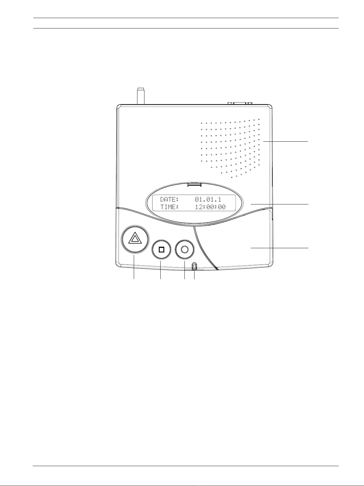
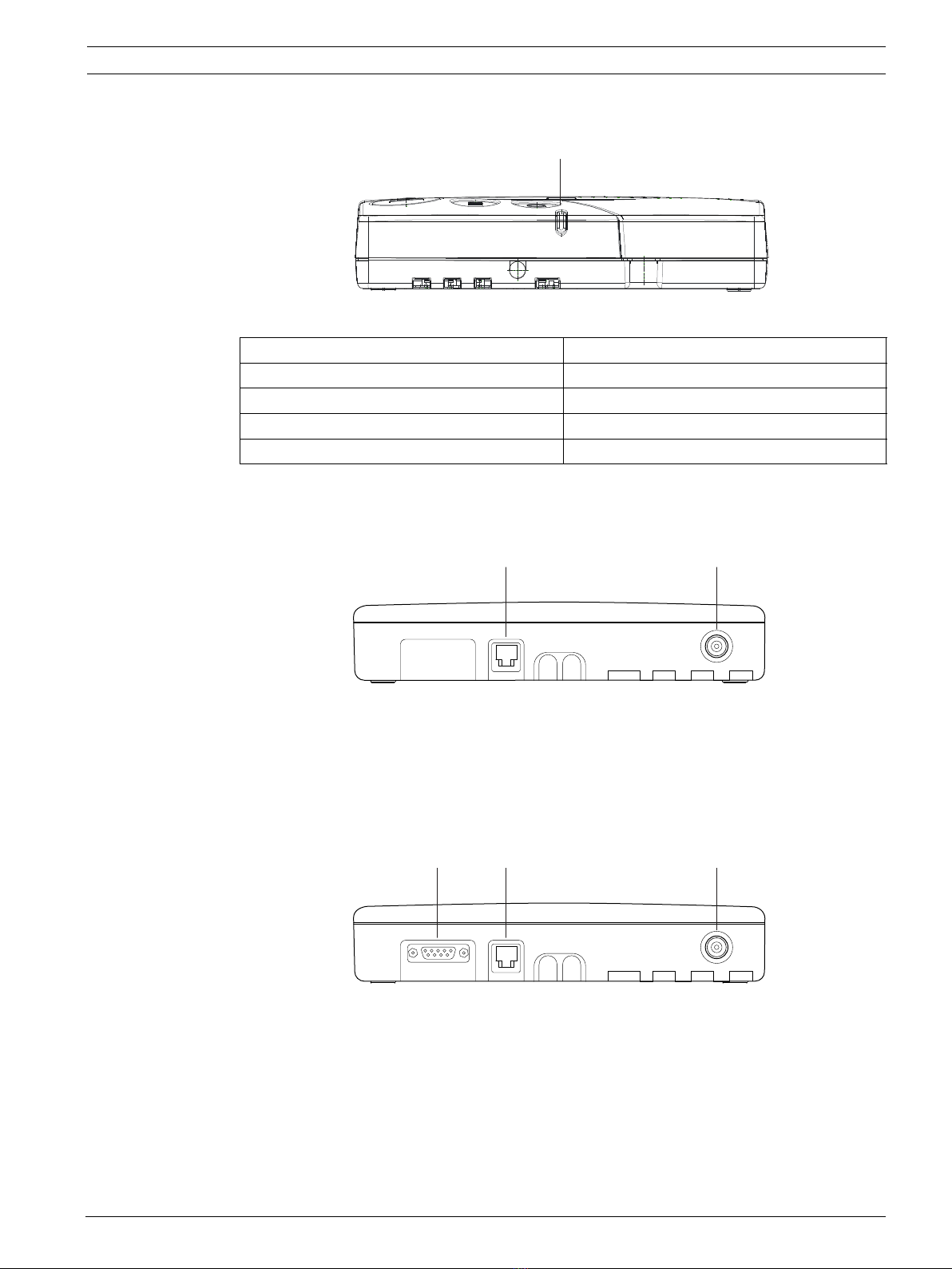
NurseCall NC8 Relay Unit Description | en7TeleAlarmUser ManualNC8_RU_UM_EN | V1.1 | 2021.122Description2.1General description2.1.1Top view1.Loudspeaker.See
Section 2.2.1 Loudspeaker, page 10
.2.Display.See
Section 2.2.2 Display, page 10
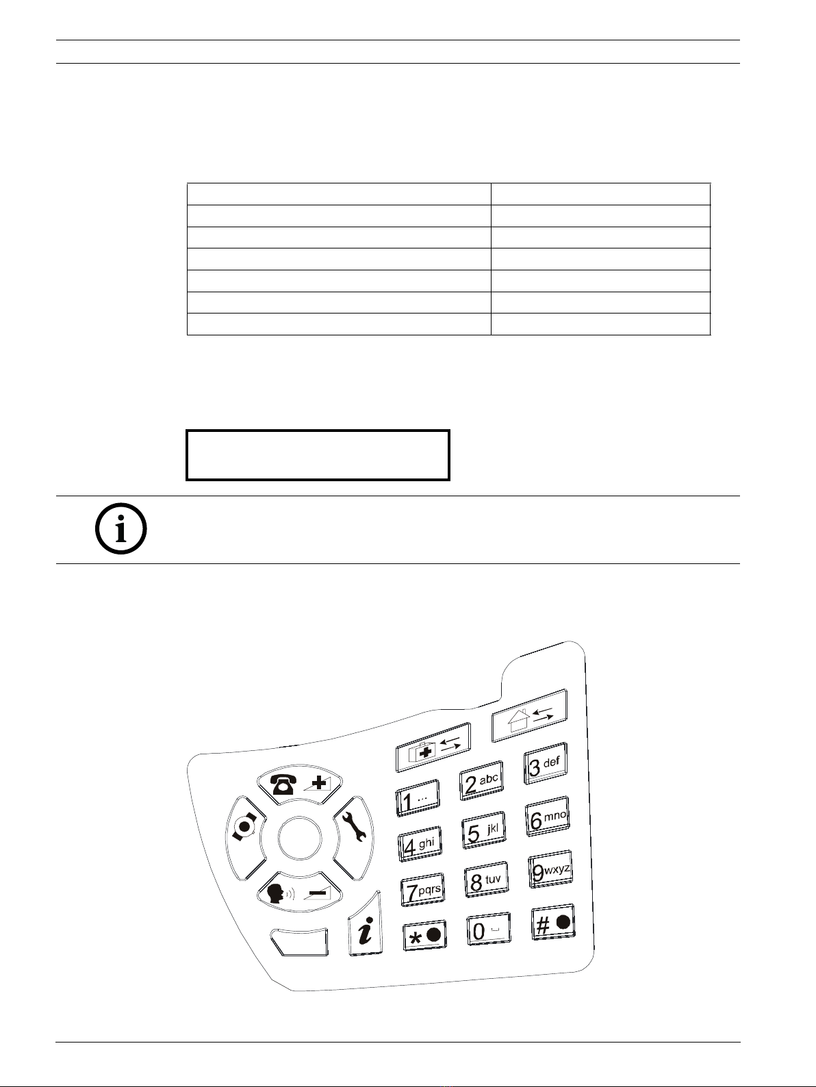
.3.Keyboard, under the cover. See
Section 2.2.3 Keyboard, page 10
.4.LED Indicator5.Yellow buttonUsed to view more details about the event or alarm currently displayed (date and time, position, etc...).6.Green buttonUsed to acknowledge an alarm locally, see
Section 5.2.3 The green button does not work, page 28
.7.Red button with lightThis button is not used. Pressing the button does not activate a function. The light blinks red during an alarm.
2
1
3
7654
5

8en | DescriptionNurseCall NC8 Relay UnitNC8_RU_UM_EN | V1.1 | 2021.12User ManualTeleAlarm2.1.2Bottom view1.Identification label.2.Cable channels.3.Wall mounting holes (distance between holes, 157 mm).See
Section 3.2.3 Wall installation, page 14
for a detailed description.4.ON/OFF switch.5.LINE socket, used for firmware update.See
Section A.5.1 LINE socket (unit bottom), page 36
for wiring.6.Socket for the Power supply adapter 230VAC/12VDC.See
Section A.5.2 Power socket (unit bottom), page 36
for wiring.
4
3
65
12
3

NurseCall NC8 Relay Unit Description | en9TeleAlarmUser ManualNC8_RU_UM_EN | V1.1 | 2021.122.1.3Front view1.LED Indicator2.1.4Relay Unit rear view1.RS-485 connector. See
Section A.5.4 RS-485 socket (unit rear), page 36
for wiring.2.Antenna connector2.1.5Relay Plus Unit rear view1.RS-232 connector, used for the printer/display interface of the Relay Plus Unit.See
Section A.5.3 RS-232 socket (Relay Plus Unit rear), page 36
for wiring.2.RS-485 connector. See
Section A.5.4 RS-485 socket (unit rear), page 36
for wiring.3.Antenna connectorStatusLEDStandby mode (normal operation)Green (permanent)Backup battery lowGreen (blinking)Power supply disconnectedGreen (flashing)Help, assistance or fireRed (blinking)
1
1 2
12 3

10en | DescriptionNurseCall NC8 Relay UnitNC8_RU_UM_EN | V1.1 | 2021.12User ManualTeleAlarm2.2Detailed description2.2.1LoudspeakerWhen one of the following alarms or messages is received by the NurseCall NC8 Relay Unit, the internal loudspeaker is activated until acknowledgement.2.2.2DisplayThe NurseCall NC8 Relay Unit is equipped with a 2 x 20 characters display that guides the operator during the programming. During normal operation, alarms and messages are displayed.2.2.3KeyboardThe keyboard has 21 alphanumeric keys. They are used to perform special commands or during normal operation.StatusLoudspeakerPower supply disconnectedDual-tone beep every minuteCall for help, reserve call, technical call4 second interval, one toneError message15 second interval, one toneDisconnection of a relay unit from RS485-bus1 minute interval, one toneCall for assistance / fire alarmContinuously dual-tone beepLocal acknowledgementShort beepNurseCall NC8 Relay Unit
V2.02 BN111.242.00A
NOTICE! This user manual is written for the unit language English USA. Certain displays may differ for the unit language English UK.
P
T
C
OK
OFF ON

NurseCall NC8 Relay Unit Description | en11TeleAlarmUser ManualNC8_RU_UM_EN | V1.1 | 2021.12KeysFunctionAccess to the printer/display setup (Relay Plus Unit only)See
Section 4.4 Printer/display setup on the Relay Plus Unit, Page22
.Increase the volume of the loudspeaker. See
Section 5.1 Adjusting the loudspeaker volume, page 26
.Decrease the volume of the loudspeaker. See
Section 5.1 Adjusting the loudspeaker volume, page 26
.Scroll down to the previous alarm/event.See
Section 5.2 Consulting the alarm or event buffer, Page 26
.Scroll up to the next alarm/event.See
Section 5.2 Consulting the alarm or event buffer, Page 26
.Confirm a value or a command.Cancel an entry or a command.Check the status of the backup battery. See
Section 6.3 Monitoring the backup battery, page 29
.Not used. to Enter a value, such as special codes.See
Section 4.3 Special settings, Page 21
.Not used.Not used.Enter a value or launch the event/alarm display mode.See
Section 5.2.1 Switching between alarm and event buffers indication, Page 27
. thenLock and unlock the keyboard.

12en | DescriptionNurseCall NC8 Relay UnitNC8_RU_UM_EN | V1.1 | 2021.12User ManualTeleAlarm2.2.4RS-485 interfaceOne NurseCall Main Unit and up to 32 NurseCall NC8 Relay Units can be connected by a RS-485 bus. The bus must be connected to pins 2 and 5 of the RS-485 socket.For connector wiring, see
Section A.5.4 RS-485 socket (unit rear), page36
.In this configuration, you always should connect the NurseCall Main Unit first. The NurseCall NC8 Relay Units must then be connected to the RS485-bus one by one, not at the same time.Relay outputIn the same connector, a potential free contact is available. It is a low current switching contact. The relay (potential free, switching power max. 48 V / 0.5 A) is activated at a call for help, call for assistance or fire alarm. This relay can be set as closing or switching contact (cycle of 10 seconds on / 10 seconds off). This feature can be used to drive a signal lamp for example.For connector wiring, see
Section A.5.4 RS-485 socket (unit rear), page36
.For relay setting, see the user manual of the NurseCall Main Unit.2.2.5AntennaThe antenna is connected to the NurseCall NC8 Relay Unit using the adapter supplied with the unit.See
Section 3.2.4 Installing the antenna, page 14
.NOTICE! Keep polarity equal when connecting further units to the RS485 bus!NOTICE! Maximum RS485-bus length: 1200 m.Use only one twisted pair cable for the interconnection.NOTICE! The receiver units located at the two ends of the bus must be terminated with a 100 Ohm resistor. See
Section 3.2.7 Connecting the RS-485, page 17
for more information about the jumper setting.

NurseCall NC8 Relay Unit Installation | en13TeleAlarmUser ManualNC8_RU_UM_EN | V1.1 | 2021.123Installation3.1UnpackingThe NurseCall NC8 Relay Unit is carefully packed for transportation.The components contained in the box are protected, but should be handled with care.Store the packaging material for further use (storage or transport).1.Take all components out of the box and place the NurseCall NC8 Relay Unit on the working space.2.Check each component in the box, in accordance with the list of contents below.3.Check that the NurseCall NC8 Relay Unit and its accessories have not been damaged during transportation.In case of defective or missing equipment, do not try to install the NurseCall NC8 Relay Unit.Contact immediately your local representative.3.1.1List of contentsDescriptionNurseCall NC8 Relay UnitPower supply adapter (Europe)230VAC/12VACAntenna 868MHz 1/2 L=17 cm FMEStraight adapter BFME-TNCRight angled bended adapter BFME-ETNC2 m Cable FCC 6/4

14en | InstallationNurseCall NC8 Relay UnitNC8_RU_UM_EN | V1.1 | 2021.12User ManualTeleAlarm3.2Installation3.2.1GeneralitiesInstall the NurseCall NC8 Relay Unit in a dry place, away from any source of heat.Tools required:–Torx T20 screwdriver.–Torx T10 screwdriver.3.2.2Installation on a piece of furnitureIt is recommended to place the NurseCall NC8 Relay Unit on a non-slippery surface. However, do not place anything (blanket or lace) on top of the unit.3.2.3Wall installationYou can fasten the NurseCall NC8 Relay Unit on a smooth wall surface using two screws. The distance between holes is 157 mm.The power line cord should be placed inside the cable channels on the bottom of the NurseCall NC8 Relay Unit.3.2.4Installing the antenna1.Use the straight adapter (4) for wall installation or the right angled bended adapter (3) for installation on a piece of furniture.2.Fasten the adapter (3) or (4) on the antenna connector (1).3.Fasten the antenna (2) on the adapter.
2
3
2
4
1

NurseCall NC8 Relay Unit Installation | en15TeleAlarmUser ManualNC8_RU_UM_EN | V1.1 | 2021.123.2.5Connecting to the mainsThe NurseCall NC8 Relay Unit is powered by an adapter (230/12 VAC).1.Plug the power adapter into a power outlet placed near the unit. It should be easily accessible at any time. 2.Connect the cable to the socket labeled 10V AC (1), under the unit.For connector wiring, see
Section A.5.2 Power socket (unit bottom), page 36
.CAUTION! In case of a different supply, the equipment must fulfill isolation requirements according to EN60950 standard (last edition).
1

16en | InstallationNurseCall NC8 Relay UnitNC8_RU_UM_EN | V1.1 | 2021.12User ManualTeleAlarm3.2.6Setting the jumpers on the communication board on the Relay Plus Unit 1.Disassemble the unit; see
Section 6.5.1 Disassembling the unit, page 30
.2.Remove the communication board; see
SectionRemoving the communication board, page 30
.3.Set the jumpers as required in your configuration. By default the jumpers are set for connection to a Display Zettler.Setting the jumpers for a Display Zettler:Setting the jumpers for a printer setup or a Display Norsk:4.Assemble the communication board and the unit. This is basically the reverse of the disassembling procedure, see
Section 6.5.1 Disassembling the unit, page 30
.

NurseCall NC8 Relay Unit Installation | en17TeleAlarmUser ManualNC8_RU_UM_EN | V1.1 | 2021.123.2.7Connecting the RS-485One NurseCall Main Unit and up to 32 NurseCall NC8 Relay Units can be connected to an RS-485 bus. Please contact a specialist for a correct installation.See
Section A.5.4 RS-485 socket (unit rear), page 36
for connector wiring.Incorrect connection:Correct connection:CAUTION! Do not use a star connection for the RS-485 network!Relay Unit n
Relay Unit 1
Relay Unit 2
Main Unit
RS-485 bus (1 twisted pair cable)
Relay Unit n Relay Unit 1
Relay Unit 2 Main Unit
100 Ω
100 Ω
NOTICE! The NurseCall NC8 Main or Relay Units located at the two ends of the bus must be terminated with a 100 Ohm resistor.

18en | InstallationNurseCall NC8 Relay UnitNC8_RU_UM_EN | V1.1 | 2021.12User ManualTeleAlarm3.2.8Connecting the RS-232 to the Relay Plus UnitConnect the printer or display device to the 9-pole SUB-D connector (1) at the rear part of the housing of the Relay Plus Unit.For connector wiring, see
Section A.5.3 RS-232 socket (Relay Plus Unit rear), page 36
.3.2.9Setting the 100 Ohm termination jumperWithin the NurseCall Main or Relay Units, the RS-485 interface can be configured with a jumper.1.Disassemble the unit as described in
Section 6.5.1 Disassembling the unit, page 30
.2.Remove the communication board as described in
SectionRemoving the communication board, page 30
.3.Put the 100 Ohm termination jumper J112 (1).4.Assemble the communication board and the unit. This is basically the reverse of the disassembling procedure, see
Section 6.5.1 Disassembling the unit, page 30
.
1
1
NOTICE! If you do not want to disassemble the NurseCall NC8 Relay Unit, you also can short-out pins 3 and 4 of the connector. This has the same effect as the jumper setting described above.See
Section A.5.4 RS-485 socket (unit rear), page 36
for connector wiring.

NurseCall NC8 Relay Unit Programming | en19TeleAlarmUser ManualNC8_RU_UM_EN | V1.1 | 2021.124Programming4.1Generalities4.1.1Using the keyboardOpen the cover carefully and use the keyboard.To access the special settings programming, press three times quickly.See
Section 4.3 Special settings, page 21
for more details.4.1.2Exit and cancel entriesPress once or several times.4.1.3Key not allowedIf you have pressed a key by mistake during the programming, a high-pitched beep is generated.4.1.4Locking and unlocking the keyboardPress then within one second to lock or unlock the keyboard.This function locks only the keyboard to prevent any false manipulation. The colored buttons on the left hand side are still available.When the keyboard is locked, a small lock appears at the bottom right of the display:4.1.5Programming time-outProgramming of the NurseCall NC8 Relay Unit terminates automatically if no entries are made on the keyboard for more than one minute.
C
OK
OFF
P
T
ON
DATE: 03.01.12 ¨
TIME: 12:12:31 ½A

20en | ProgrammingNurseCall NC8 Relay UnitNC8_RU_UM_EN | V1.1 | 2021.12User ManualTeleAlarm4.2First use4.2.1List of original factory settings* Locating mode and identification number are set at first use. To change a value, reset the unit. See
Section 4.3.2 Resetting all the parameters and buffers, page 21
.4.2.2Parameters set by the NurseCall Main UnitThe parameters listed below are programmed in the Main Unit and are applied to the Relay Unit. See the NurseCall Main Unit user manual.–Display mode–Unit language–Date and time–Local acknowledgement and the access code–Output relay function and mode4.2.3Locating mode and identification number1.Disconnect the NurseCall NC8 Relay Unit from the RS-485 bus.2.Switch the NurseCall NC8 Relay Unit on with the switch located at the bottom of the unit. Wait for the following display to appear:3.Enable (ON) or disable (OFF) the indication of the transmitter position (locating mode) on the NurseCall NC8 Relay Unit display. It must be the same as in the NurseCall Main Unit. Press to disable or to enable the locating mode.4.The identification number of the NurseCall NC8 Relay Unit must now be attributed.The identification number is attributed by the NurseCall Main Unit upon connecting the RS-485 bus corresponds to the order of connection. It can also be set manually. The range for this value is (A, B, C, ..., Y, Z, a, b, c, d, e, f) for a maximum of 32 Relay Units.Automatic attribution by the NurseCall Main Unit5.a. Press or the Red button to erase any previous selection. The black box remains.ParameterOriginal Factory SettingPage* Locating modeOn
20
* Identification numberNo value
20
Assistance and fire priorityNo
21
Special texts in GermanNo
22
Printer/display setup (Relay Plus Unit only)None
22
Speaker volumeMidrange
26
LOCATING ?
( OFF / ON )
RELAY UNIT ID: ·
( + / - )
Other manuals for TeleAlarm NurseCall NC8
1
Table of contents
Popular Relay manuals by other brands

C&S Electronics
C&S Electronics CSMPA22-2S manual

ZIEHL
ZIEHL TR111V operating manual

Littelfuse
Littelfuse 777 Series Wiring diagram

MITSUBISHI ELECTRIC ENGINEERING
MITSUBISHI ELECTRIC ENGINEERING DG2BK1TB Series user manual

Videx
Videx 2213 Technical manual

CD Automation
CD Automation REVO S 3Ph Series user manual