.......................................................................................................................................1
1 Introduction..................................................................................................................1
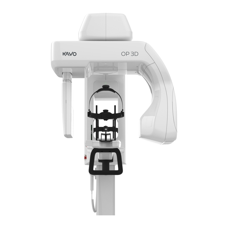
1.1 ORTHOPANTOMOGRAPH™ OP 3D Pro ............................................................ 1
1.2 Intended use ......................................................................................................... 2
1.3 Associated documentation .................................................................................... 2
1.4 References............................................................................................................ 2
1.5 Abbreviations used in this manual ........................................................................ 3
1.6 Warnings and precautions .................................................................................... 4
1.6.1 Warnings for cross infection....................................................................... 4
1.6.2 Warnings to be observed during installation and service........................... 4
1.6.3 Cautions for Electrostatic discharge........................................................... 6
1.6.4 General warnings ....................................................................................... 6
1.7 Disclaimer ............................................................................................................. 9
1.8 Disposal ................................................................................................................ 9
2 Unit description .........................................................................................................11
2.1 Main parts and controls....................................................................................... 11
2.2 Patient positioning lights ..................................................................................... 13
2.3 Patient positioning panel ..................................................................................... 17
2.3.1 Cephalometric unit positioning panel ....................................................... 17
2.4 Main control panel............................................................................................... 18
2.5 Unit identification labels ...................................................................................... 19
2.6 Unit movements .................................................................................................. 20
2.7 Finger guards ...................................................................................................... 21
2.8 Emergency stop switch ....................................................................................... 22
3 Electrical description ................................................................................................25
3.1 Circuit boards ...................................................................................................... 25
3.2 Electrical component location ............................................................................. 27
3.3 List of circuit boards and electric devices............................................................ 30
3.4 Schematic diagrams............................................................................................ 33
3.5 Circuit board descriptions.................................................................................... 47
3.5.1 R3220 CPU (Central Processing Unit)..................................................... 47
3.5.2 CEPH R3210............................................................................................ 48
3.5.3 R3300 IO1 (Input/Output 1)...................................................................... 49
3.5.4 R3400 NGEO IO2 (Input/Output 2 Board) ............................................... 50
3.5.5 R3710 X-Ray power supply ..................................................................... 52
3.5.6 R3810 X-Ray generator ........................................................................... 53
3.5.7 R5100 3-Phase stepper driver ................................................................. 55
3.5.8 R5300 Panel raw power supply ............................................................... 56
3.5.9 EA100 Power distribution board............................................................... 57
3.5.10 EA200 Connector board........................................................................... 59
3.5.11 EA300 Connector board........................................................................... 61
3.5.12 EB100 Rotator opto board ....................................................................... 61
3.5.13 EC100 Pan sensor connector board ........................................................ 62
3.5.14 ED100 Pan sensor connector board ........................................................ 63
3.5.15 ED200 Ceph sensor connector board...................................................... 64
3.5.16 EE100 Ceph encoder opto board............................................................. 65
3.5.17 EE200 Ceph sensor connector board ...................................................... 66
3.5.18 EG100 Dual opto board ........................................................................... 67
