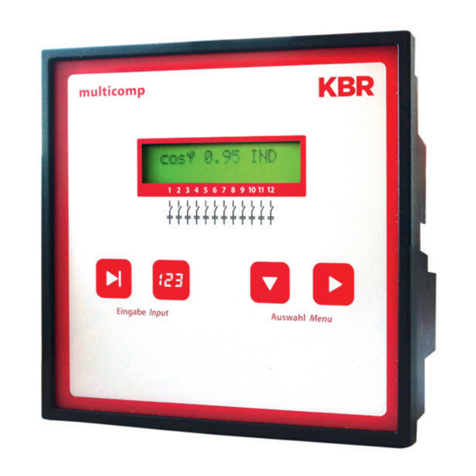
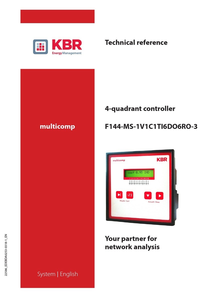
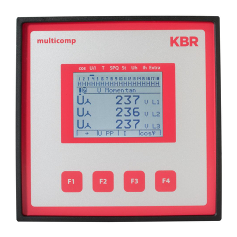
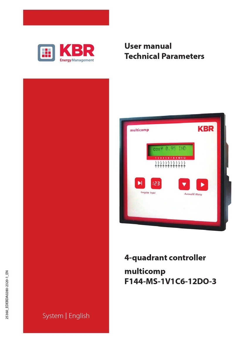
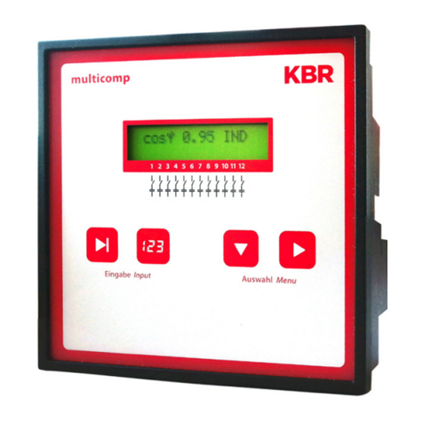
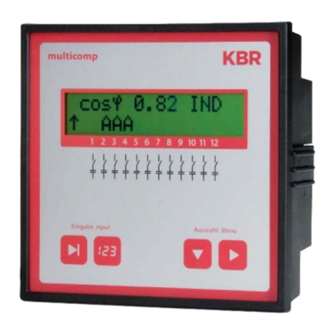
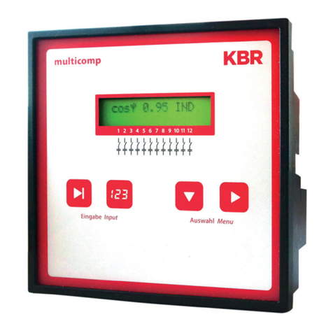
KBR Multicomp 2F144-NC-1V1C06RO Operating instructions

2F144-NC-1V1C06RO
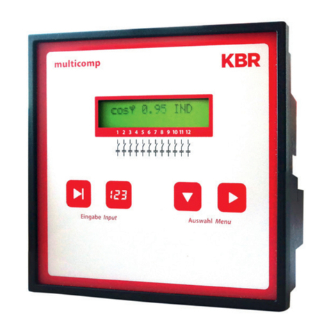
2F144-NC-1V1C12RO
multicomp
4-quadrant
controller
Operating instructions
Technical parameters
Yo u r n e t w o r k a n a l ys i s
specialist
Optimizing
Monitoring
Optimizing

KBR GmbH
Am Kiefernschlag 7
D-91126 Schwabach
T +49 (0) 9122 6373-0
F +49 (0) 9122 6373-83
E info@kbr,de
www.kbr.de

Page I von IV
3510-1 GB
Dear Customer
We would like to thank you for choosing a KBR GmbH quality product.
In order to familiarize yourself with the operation and programming of the device and always be able to use the
whole functionality of this high-quality product, we recommend that you read this manual thoroughly.
The individual chapters serve to explain the technical details of the device and show how to avoid damage by
means of proper installation and commissioning.
The manual is included in the scope of delivery of the device and must be accessible for the user at all times
(e.g. in the switchgear cabinet). Even when the device is resold to third parties, the manual remains part of the
device.
Although we used the utmost care in assembling this manual, we would like to thank you in advance for notify-
ing us about any errors or ambiguous descriptions that might be in it. You will find a form for corrections in the
appendix.
Sincerely,
KBR GmbH Schwabach
Preface

Page II von IV
3510-1 GB
Safety Precautions
This manual contains notes that must be observed for your personal safety and to avoid damage to equipment.
Notes are identified by a warning sign or an info symbol according to the degree of hazard they represent.
Disclaimer
The contents of this manual has been checked with the described hardware and software components. Cer-
tain deviations, however, cannot be excluded, so the manufacturer is not liable for complete conformity. The
specifications made in this manual are checked on a regular basis, necessary corrections are included in the
next revision.
We appreciate your corrections and comments.
© KBR-GmbH
Subject to change
aDanger
means that death, major injuries or damage will occur in case the
appropriate safety measures are not performed.
aWarning
means that death, major injuries or damage may occur in case the
appropriate safety measures are not performed.
aCaution
means that minor injuries or damage may occur in case the appropriate
safety measures are not performed.
bNote
is an important information on the product, product handling or the
respective part of the user manual to which special reference is made.
Safety Precautions

Page III von IV
3510-1 GB
General Safety Precautions
In order to prevent operating errors, handling of the device is kept as simple as possible. This way, you will be
able to use the device very soon.
In your own interest, however, you should read the following safety precautions carefully.
aWarning
During installation, the applicable DIN / VDE regulations must be obser-
ved!
Mains connection, setup and operation of the device must only be per-
formed by qualified personnel. Qualified personnel as understood in the
safety precautions of this manual are persons authorized to setup,
ground and mark equipment, systems and wiring systems in
accordance with applicable standards.
To avoid the hazard of fire and electrical shock, the device must not be
subjected to rain or other humidity!
Before the device is connected to the mains, you will have to check
whether the local mains conditions comply with the specifications on the
manufacturer's label. A wrong connection may destroy the device!
When connecting the device, the connection chart must be observed
(see chapter "Connection chart") and the connection lines must be pow-
erless. Only use proper line material and watch the correct polarity
when wiring!
In order to ensure proper and safe operation of the product, it must be
transported, stored, installed and mounted in accordance with the speci-
fications and operated and maintained carefully.
A device showing visible damage must by all means be considered as
unfit for operation and must be disconnected from the mains!
Error detection, repairs and maintenance work may only be carried out
in our facilities or after contacting our service team. Every warranty obli-
gation of the manufacturer expires if the device is opened without writ-
ten consent from our service team. Proper operation can no longer be
guaranteed!
Opening the device may expose parts under voltage. Capacitors in the
device may still be loaded even if the device was disconnected from all
voltage sources. It is generally not allowed to operate the open device!
In facilities subject to hazard of lightning, lightning protection must be
provided for all input and output lines (recommendations see chapter
"Protective measures")!
Safety Precautions

Page IV von IV
3510-1 GB
Product Liability
With these product, you have acquired a quality product.
In its manufacture, only components of the highest reliability and quality were used. Each device is subject to
long-term testing before it is delivered.
For information on product liability, please refer to our General Terms and Conditions for electronic devices.
The warranted properties of the device apply only if it is operated in accordance with its intended use!
Disposal
Please dispose of defective, outdated or no longer used devices properly.
At your request, we will be pleased to dispose of the devices for you.
Product Liability / Disposal

Operating instructions multicomp
Version 1.00 Page 1 of 29
EDEBDA0144 / 0511-1 GB
Table of Contents
1 Controller functional principle .............................................................2
2 Operating and display panel ................................................................3
3 Mounting and electrical connection of the device .............................5
3.1 General, very important! ....................................................................................5
3.2 Current transformer connection and measurement voltage ..........................5
3.3 Current transformer dimensions .......................................................................5
3.4 Standard connection chart measurement voltage Ph-N .................................6
3.5 Standard connection chart measurement voltage Ph-Ph ...............................7
4 Commissioning the facility ...................................................................8
4.1 General commissioning notes ...........................................................................8
4.2 Compensation facility with controller ...............................................................8
5 Navigation and device displays ...........................................................9
6 Main menu displays ............................................................................11
7 Description of the individual display windows .................................13
7.1 Initialization window .........................................................................................13
7.2 Commissioning window if no stage power is programmed .........................13
7.3 Start menu window ...........................................................................................16
7.4 Stage state window ...........................................................................................17
7.5 Service window .................................................................................................17
7.6 Commissioning window ...................................................................................18
7.7 Switching performance window ......................................................................20
7.8 Error message menu ........................................................................................21
7.9 Window Extras ..................................................................................................22
8 Notes on detecting errors ...................................................................23
9 Facility and safety devices maintenance ..........................................24
10 Setting range of the parameters configurable ..................................25
11 Technical Data .....................................................................................26
11.1 Measuring and display values .........................................................................26
11.2 Measuring accuracy .........................................................................................26
11.3 Measuring principle ..........................................................................................26
11.4 Device memory .................................................................................................27
11.5 Other limits: .......................................................................................................27
11.6 Power supply .....................................................................................................27
11.7 Hardware inputs and outputs ..........................................................................27
11.7.1 Hardware inputs .....................................................................................................27
11.7.2 Hardware outputs ..................................................................................................27
11.8 Electrical connection ........................................................................................27
11.9 Mechanical data ................................................................................................28
11.10 Standards and Miscellaneous .........................................................................28
11.11 Overvoltage category .......................................................................................28
12 Selection of lines and fuses ...............................................................29
Operating instructions multicomp
Page 2 of 29 Version 1.00
EDEBDA0144 / 0511-1 GB
1 Controller functional principle
The controller's micro processor acquires the supply voltage and the current consumption of the downstream
facility via measuring transformer inputs (A/D transformer) and calculates the active and reactive power ratios
of the network. The controller operates based on a 4 quadrant operation.
• Energy recovery in generator operation is recognized and displayed (the LCD shows a flashing
„G”). During this time, compensation to CosPhi 1.00 (recovery CosPhi) will be performed. To avoid
alternating switching operations when switching between recovery and consumption,
compensation to the recovery CosPhi is performed for 15 minutes when recovery is detected.
During this period of time, the set target-CosPhi is disabled.
The compensation power required for the target CosPhi is calculated continuously. If the power difference
corresponds to the set hysteresis (switch on and off hysteresis), the staged switching is performed in
accordance with the compensation power required. Manually switched stages, however, are not included in the
optimization. In case of identical stages with identical power, the stage disconnected for the longest time is
connected.
With only a few switching operations an optimal adjustment is obtained. Even for large facilities, sensitive
controls may be set up with only a few modules. No stage ratios need to be considered. After compensation,
switching operations are interrupted for a programmable time. In order to avoid alternating switching
operations, the stage switch off hysteresis can be increased to up to 150% of the lowest stage power.
For light load operation (secondary measurement current under the limit (< 20mA), the stages are switched off
after 1 hour.
The programmed values are saved on an EEPROM and will thus not be lost after a network failure.
The measuring cycle of the controller for recording the necessary network parameters takes approx. 20 ms.
In case of failure, the compensation stages are switched off and "overvoltage" is displayed.
bNote!
Limiting value for overvoltage switch-off = nominal voltage + 10%
(taking into account the measurement voltage transformer ratio).
The value of 10% is unchangeable and serves the safety of the
compensation facility
The reset hysteresis is 1% of the rated voltage.

Operating instructions multicomp
Version 1.00 Page 3 of 29
EDEBDA0144 / 0511-1 GB
2 Operating and display panel
multicomp 2F144-NC-1V1C6RO
1
2
34
multicomp 2F144-NC-1V1C12RO
1
2
34

Operating instructions multicomp
Page 4 of 29 Version 1.00
EDEBDA0144 / 0511-1 GB
Operating elements:
1 LCD displaying current status and user prompts
2 Number of controller output lines possible
3 Two sensor buttons for parameter programming
4 Two sensor buttons for menu selection
General notes on operating the sensor buttons:
Basic controller settings (default settings):
• Consumption target CosPhi: 0.95 inductive
• Recovery target CosPhi: 1.00
• Alarm CosPhi: 0.92 inductive
• Main transformer current: Primary current 1000 A
• Secondary current 5 A
• Measurement voltage: Primary voltage 400 V Ph-Ph (equivalent 230V Ph-N)
• Secondary voltage 400 V Ph-Ph (equivalent 230V Ph-N)
• Rot.field U: L1-N
• Rot.field I: L1
• Attenuation coefficient for current: 2
• Attenuation coefficient for voltage: 2
• Attenuation coefficient Qmiss: 2
• Alarm delay: 20 minutes (1200 seconds)
• Idle time: 30 seconds
• Switching interval: 8 seconds
• Hysteresis connection: 100% of smallest stage power
• Hysteresis disconnection: 100% of smallest stage power
• Limit switching cycles: 80000
• Switching cycle count: Activated by programmed limit
• Stage switching mode: Automatic
• Scanning frequency: Automatic
• Harmonics monitoring: Activated by programmed limit
• THD limit: 8%
• Stage power: not programmed
• Stage power monitoring: disabled
• Discharge time: 60 seconds
• Password No password (9999, meaning all functions are accessible)
• Contrast setting: 4
The controls in the assembled compensation units are preset.
The following needs to be checked or set:
• Target CosPhi according to energy supplier regulations
• (for kVA tariff CosPhi = 1)
• Primary current and secondary current in accordance with input current transformer.
• If required voltage transformer ratio
Button UStart input for configuration and reset.
Button VValue change during configuration
Button WNavigation through submenus
Button XNavigation through main menus and save button during configuration
Key combinations:
Buttons Xand VDeletion of cumulated values
Perform reset

Operating instructions multicomp
Version 1.00 Page 5 of 29
EDEBDA0144 / 0511-1 GB
3 Mounting and electrical connection of the device
3.1 General, very important!
• Tighten all screws and connections as otherwise warranty will be void!
• The device needs to be installed and operated in accordance with valid VDE regulations
(in particular VDE 0100) and energy supplier regulations.
Connection cross-sections and fuse protection table: see attachment
3.2 Current transformer connection and measurement voltage
If possible, mount the transformer in the phase that corresponds to L1 of the compensation facility
(determine by means of voltage measurement). All capacitor and consumer currents need to be
determined. In case of unbalanced phase load (small facilities), install the transformer in the phase with
the highest load.
- P1 (K) to energy supply (indicated on the transformer).
- P2 (L) to load
- S1 (k) with terminal k(controller terminal 20) and
- S2 (l) with terminal l(controller terminal 21) needs to be connected in the compensation facility
(use two-color cable!).
Line cross-section: up to 3 m = 1.5 mm², up to 6 m = 2.5 mm². For greater distances, we recommend
using a 1 A transformer. The controller is designed for the connection of 5 A and 1 A transformers,
switching is set in the configuration.
If using existing transformers, the current paths always need to be connected in series.
The secondary transformer current needs to be at least 12 mA. For smaller currents, no capacitors will
be connected (display shows “missing current“).
Measurement voltage connection according to connection chart.
3.3 Current transformer dimensions
The current transformer is dimensioned based on the current consumption of the consumers and not the
capacitor current. If other measuring devices are connected to a transformer in addition to the reactive power
controller, the transformer power needs to be dimensioned accordingly. Also, losses occur in the current
transformer line that need to be considered in case of large distances between the transformer and the
controller.

Operating instructions multicomp
Page 6 of 29 Version 1.00
EDEBDA0144 / 0511-1 GB
3.4 Standard connection chart measurement voltage Ph-N
For voltage supply, see nameplate.
only multicomp 2F144-NC-1V1C12RO

Operating instructions multicomp
Version 1.00 Page 7 of 29
EDEBDA0144 / 0511-1 GB
3.5 Standard connection chart measurement voltage Ph-Ph
For voltage supply, see nameplate.
only multicomp 2F144-NC-1V1C12RO

Operating instructions multicomp
Page 8 of 29 Version 1.00
EDEBDA0144 / 0511-1 GB
4 Commissioning the facility
4.1 General commissioning notes
• Switch on a sufficient number of inductive consumers (e.g. motors) prior to switching on the compensation
facility. A transformer current of at least 15 mA needs to flow in the secondary circuit for the controller to be
activated. Below this limit the display will show “missing transformer current”.
• The transformer connection needs to be checked (transformer ratio too high?).
• Before switching on the controller, measurement voltage must be available.
No error message is displayed, but the learning mode cannot be started.
• If stage power has been programmed, the power factor CosPhi should be displayed after initialization.
Normally, when no capacitors are connected, CosPhi is in the range of 0.6 to 09. inductive,
(e.g. CosPhi 0.80 ind).
• If a capacitive value is displayed, or if there is a flashing G symbol, the phase allocation of current and
voltage measurement is incorrect. In the Commissioning programming menu, the phase allocation can be
changed using the function Rot.field U and Rot.field I (provided that there is no generator operation at the
time).
• The first switching operation may take up to 60 seconds. The stages are switched in a set 1 second
interval until compensation. The CosPhi displayed has to converge target CosPhi.
4.2 Compensation facility with controller
The controller is preset as a component of a compensation facility (refer to connection diagram of
compensation facility). The following need to be programmed or checked:
• Target CosPhi according to energy supplier regulations.
• Primary and secondary current in the main circuit according to the mounted transformer.
• If required, set measurement voltage transformer data.
• If no stage power has been programmed, the controller will switch into the Commissioning menu.
Subsequently, stage power programming can be performed in the settings menu, or using the learning
process.
The programmed values are saved on an EEPROM and will thus not be lost after a network failure.
bNote!
The learning process is started in the Commissioning menu,
in the Activate learning mode submenu.

Operating instructions multicomp
Version 1.00 Page 9 of 29
EDEBDA0144 / 0511-1 GB
5 Navigation and device displays
Init
Initialization period
Start menu
Inst. CosPhi
Stage state
Start menu
Measurement voltage
Main current
Start menu
Apparent power
Active power
Start menu
Reactive power
Miss.comp.power
Start menu
Network frequency
Harm. U tot.
Start menu
Firmware Version
Start menu
Current CosPhi
Stage state
Stage state
next îD
Auto / off / on
Stage 01
Status
Auto / off / on
Stage 12
Status
Stage state
next îD
Service
next îD
Auto / off / on
Stage 06
Status
Service
Stage 01
Switching cycles
Commissioning
next îD
Service
Stage 06
Switching cycles
Service
Stage 12
Switching cycles
Service
Switching cycles
delete (all)
Service
Miss.comp.power
Maximum
(delete value)
Service
KF-U
Service
3rd Harm. U
Service
13th Harm. U
Commissioning
Enter password
Password status
Commissioning
Main current
primary
Commissioning
Main current
secondary
Commissioning
Target CosPhi
Commissioning
measurement voltage
primary
Commissioning
measurement voltage
secondary
Commissioning
Discharge time
Commissioning
Rot.field U
Commissioning
Rot.field I
Commissioning
Learning mode
activated
Commissioning
Stage 01
Stage power
Commissioning
Stage 06
Stage power
Commissioning
Stage 12
Stage power
Commissioning
next îD
Additional main
menus
Additionalstagesonly
for multicomp
2F144-NC-12RO
Additionalstages only
for multicomp
2F144-NC-12RO
Additionalstagesonly
for multicomp
2F144-NC-12RO

Operating instructions multicomp
Page 10 of 29 Version 1.00
EDEBDA0144 / 0511-1 GB
Switching
performance
next îD
Switching
performance
Hysteresis
Connection
Switching
performance
Hysteresis
Disconnection
Switching
performance
Alarm
delay
Switching
performance
Idle time
Switching
performance
Switching interval
Switching
performance
Alarm CosPhi
Switching
performance
Attenuation I
Error message menu
next îD
Switching
performance
next îD
Error message menu
No meas.
voltage
Extras
next îD
Error message menu
Stage power
insufficient
Error message menu
Facility too small
FTS
Error message menu
THD U high
Error message menu
Switching cycle limit
exceeded
Error message menu
Missing current
Error message menu
Light load operation
Error message menu
next îD
Extras
Display
language
Extras
Limit
THD
Extras
Limit
Switching cycles
Extras
Scanning frequency
Extras
Stage power
monitored
Extras
Reset
Extras
Contrast setting
Extras
next îD
Start menu
Switching
performance
Attenuation Qm
Switching
performance
Attenuation U

Operating instructions multicomp
Version 1.00 Page 11 of 29
EDEBDA0144 / 0511-1 GB
6 Main menu displays
For the current displays and the controller configuration, the following main menus with their submenus can be
used: see item 5 Navigation and device displays:
Initialization menu – no input possible
multicomp 2F144-NC-1V1C12RO only
Start menu window - display of current values
multicomp 2F144-NC-1V1C12RO only
Stage state window – stage state can be changed
bNote!
In the next chapter, the main menus and their submenus are described
in detail.
multicomp 06 eco
Initialisation
multicomp 12 eco
Initialisation
cos¢ 0.71 IND
BAAAA
cos¢ 0.71 IND
BAAAA
Stage state
next îD

Operating instructions multicomp
Page 12 of 29 Version 1.00
EDEBDA0144 / 0511-1 GB
Service window – display and deletion options
Commissioning window – entry of operating parameters
Switching behavior window – influencing switching behavior
Error message menu – editing the error message dialog
Extras window – setting special parameters
Service
next îD
Commissioning
next îD
Switch. perform.
next îD
Message menu
next îD
Extras
next îD

Operating instructions multicomp
Version 1.00 Page 13 of 29
EDEBDA0144 / 0511-1 GB
7 Description of the individual display windows
7.1 Initialization window
multicomp 2F144-NC-1V1C12RO only
This is displayed after connecting the supply voltage to the controller.
7.2 Commissioning window if no stage power is programmed:
If the multicomp 2F144-NC-1V1C6/12RO is being commissioned for the first time, after connecting the
supply voltage, the initializing window is displayed, followed by the Commissioning window.
This menu is used for the initial commissioning of the controller, where all the necessary settings can be
made.
If a controller already integrated into a KBR compensation facility by default should be used, only the
parameters of the current transformer have to be configured.
Selection of submenus with button W.
Password protection:
To protect a facility against unauthorized access of the configured parameters, a password can be entered
(4-digit number code, e.g. 4321).
In case the password gets lost somehow, the controller can be unlocked with the master password 1976.
When unlocking a password protected controller, it is possible to press a button within 300 seconds.
If no button is pressed during this period, the controller is locked again.
The password can be configured by pressing the button Uto start entering and changing the entry position,
Vto change or set the value and Xto save the entry.
multicomp 06 eco
Initialisation
multicomp 12 eco
Initialisation
aCaution!
During the initialization period, please do not press any sensor
buttons; they are adjusted automatically to ensure correct operation.
Commissioning
next îD

Operating instructions multicomp
Page 14 of 29 Version 1.00
EDEBDA0144 / 0511-1 GB
Configuring current transformer values:
For the compensation controller to function properly, all parameters concerning the current transformer have
to be set correctly. Primary and secondary current of the transformer have to be set (submenu Iprim. / Isec.).
These parameters can be read on the nameplate of the current transformer. In addition, the phase allocation
of the transformer has to be set correctly. In the controller, the phase (L1, L2, L3) in which the current
transformer is integrated has to be set (submenu Rot.field I). If the transformer connections are mixed up
(k and l interchanged), this can be corrected with the setting -L1, -L2 and -L3.
Setting target CosPhi:
You can ask your energy supply company for the target CosPhi, which should be set up at this point.
The target CosPhi is by default set to 0.95 inductive (see chapter Default settings).
Setting the voltage transformer parameters:
Specify the primary voltage in the U primary submenu, the secondary voltage under U secondary and the
phase allocation of the measurement voltage under Rot.field U. These settings apply to a standard network
(voltage Ph-Ph: 400V primary, 400V secondary). With measurement voltages of over 500V, the parameters
specified on the voltage transformer have to be configured, e.g. 690V / 100V, as well as the measuring mode,
e.g. L12 for the measurement voltage connection between the phases L1 and L2.
Setting the discharge time:
Checking or, if required, changing the discharge time of the capacitor stages is a very important menu item.
Possible discharge times are 0, 3, 30, 60, 300, 600, 900 sec. Please make sure that the correct value is set,
otherwise the capacitors could be damaged.
Configuring the capacitor stages:
There are two ways of configuring the capacitor stages: The stages can be configured manually or using the
learning mode.
It is important to set the stage power correctly. The stage power can be looked up on the nameplate of the
stage or the circuit diagram and then programmed manually. In thiscase, skip the menu itemActivate learning
mode and individually enter the power value vor each stage.
If you want to Activate the learning mode, you have to make sure thatall previous submenu parameters have
been set correctly.
The learning mode is activated by pressing the button U. Change to Yes with the button Vand confirm with
button X.
The learning mode automatically sets the stage power. However, this value has to be checked after each time
the learning process is performed.
aCaution!
If there is no measurement voltage, the learning mode menu does not
appear.
This manual suits for next models
1
Table of contents
Other KBR Controllers manuals

KBR
KBR F144-3PH User manual

KBR
KBR multicomp 4D6-ESBSDS-1V1C6RO Operating instructions

KBR
KBR multicomp F144-MS-1V1C1TI6RO-3 User manual

KBR
KBR multimax 3D6 User manual

KBR
KBR F144-3PH User manual

KBR
KBR F144-MS-1V1C6-12DO-3 User manual

KBR
KBR multimax D6-5 Series User manual

KBR
KBR multicomp F144-MS-1V1C1TI6RO6DO-3 User manual

KBR
KBR multicomp F144-NC-1V1C6DO6RO-2 Use and care manual

KBR
KBR F144-MS-1V1C6-6RO-6DO-3 User manual