KBR multimax 3D6 User manual

EDEBDA0210-3313-1_EN
User manual
Technical parameters
Your partner for
network analysis
Load management system
3D6
multimax
System IEnglish

© KBR Kompensationsanlagenbau GmbH
Subject to typesetting and printing errors
or technical changes.
2
EDEBDA0210-3313-1_EN

V3.00 3
EDEBDA0210-3313-1_EN
KBR multimax 3D6
Table of contents
1 Introduction......................................... 5
1.1 User manual .......................................... 5
1.2 Intended use......................................... 5
1.3 Explanation of
safety relevant symbols .................... 6
1.4 Safety notes........................................... 7
1.5 Product liability.................................... 8
1.6 Disposal .................................................. 8
2 Range of functions ............................. 9
2.1 Monitoring of the energy
consumption ........................................ 9
2.2 Energy optimization system with
trend calculation ................................. 9
2.3 Switching the consumers using
compensation power ........................ 9
2.4 Switch-o of consumers via relay
outputs..................................................10
2.5 Decentralization
through substations.........................10
2.6 Status recording via message
modules................................................10
2.7 Maximum prewarning contact ....10
2.8 Power measurement
by means of energy pulses
of the energy supplier.....................11
2.9 Counter pulse monitoring .............11
2.10 Measuring period synchronization
by energy supplier pulse................11
2.11 3 target values for consumption
limits ......................................................11
2.12 Error message functions.................12
2.13 Long term memory ..........................12
3 Device overview ................................13
4 Installation...........................................14
4.1 Device memory,
battery-buered................................14
4.1.1 Inserting or replacing backup
battery:..................................................14
4.2 Device installation ............................15
4.3 Connections........................................15
5 Control and display panel..............17
5.0 Description of buttons and
displays, factory settings, setting
ranges....................................................17
6 Overview of system parameters..24
7 Description of parameters.............25
7.0.1 General parameters..........................25
8 Line parameters.................................31
8.1 Counter inputs ...................................38
8.2 Module management......................39
8.3 I/O parameters ...................................39
8.4 Clock time / date ...............................40
8.5 Bus parameters ..................................41
8.6 Display parameters...........................41
8.7 Alarm parameters .............................43
8.8 Password / reset.................................43
9 Description of the display..............45
9.1 Pactual...................................................45
9.2 Potential ...............................................46
9.3 Line data...............................................46
9.4 I/O status ..............................................47
9.5 Ptarg trackes .......................................47
9.6 Counter values ...................................48
9.7 Current error messages...................48
10 Technical data multimax 3D6 .......49
10.1 General technical data
of additional modules .....................49
10.2 Technical data of the multimax 3D6
basic module ......................................50
KBR multimax 3D6
V3.00
EDEBDA0210-3313-1_EN
4
Table of contents
10.2.1 Operating and display elements 50
10.2.2 Device memory..................................50
10.2.3 Power supply ......................................51
10.2.4 Hardware inputs...............................51
10.2.5 Electrical connection .......................51
10.2.6 Hardware outputs.............................52
10.2.7 Mechanical data and dimensioned
drawing of the basic module........52
10.2.8 Environmental conditions /
electrical safety ..................................53
10.2.9 Mechanical data and
dimensioned drawing of the
multimax 3F96-DS display.............54
10.2.10 Serial interface ...................................55
10.2.11 Protective measures - overvoltage
and lightning protection................55
11 Connection of
additional modules ..........................56
11.1
Functional description relay output
module multisio 1D4-4RO ISO ......... 56
11.2 Relay output module
connection chart...............................56
11.3 Relay output module LED display57
11.4 Function of scan button .................57
11.5 Function of the DIP switches ........58
11.6 DIP switch settings ...........................59
11.7 Functional description digital
input module multisio 2D2-4DI...59
11.8 Digital input connection chart.....60
11.9 Digital input module LED display60
11.10 Function of scan button .................61
11.11 Function of the DIP switches ........61
11.11 DIP switch settings ...........................62
Settings ................................................................64
Output lines energy control system..........70
Output lines energy control system..........71

V3.00
KBR multimax 3D6
EDEBDA0210-3313-1_EN
5
Introduction
1 Introduction
Thank you for choosing this KBR quality product.
In order to familiarize yourself with the operation and conguration of the
device, we recommend that you read this manual thoroughly, so that you are
able to make use of the entire range of functions of this high-quality product.
The individual chapters serve to explain the technical details of the device and
show how to avoid damage by means of proper installation and start-up.
1.1 User manual
This user manual is included in the scope of delivery of the device and must be
accessible for the user at all times (e.g. in the switchgear cabinet). Even when
the device is resold to third parties, the manual remains part of the device.
Although we used the utmost care in assembling this user manual, we would
like to thank you in advance for notifying us about any errors or ambiguous
descriptions you might notice.
1.2 Intended use
This device is intended for the optimization of energy consumption and to
avoid expensive load peaks.
The system assists you in monitoring the energy consumption of your devices,
helps you to make optimum use of your tari and permanently lower your
energy costs.
However, its use cannot replace the careful planning of your system.
Furthermore, it is absolutely necessary that you take the time to carefully
congure your system in the device and plan how you want to switch-o your
consumers before you put it into operation.

KBR multimax 3D6
V3.00
EDEBDA0210-3313-1_EN
6
1.3 Explanation of safety relevant symbols
This user manual contains notes that must be observed for your personal safety
and to avoid damage to equipment. These notes are identied by a warning
sign or information symbol, depending on the degree of hazard they represent.
"Warning" means that death, major injuries or damage may occur in case the
appropriate safety measures are not taken.
"Caution" means that minor injuries or damage may occur in case the
appropriate safety measures are not taken.
"Note" is an important information on the product, operation or the respective
part of the user manual to which special reference is made.
Disclaimer
The content of this user manual has been carefully reviewed in terms of
the hardware and software described. Certain deviations, however, cannot
be excluded, and the manufacturer is not liable for complete conformity.
The specications made in this user manual are checked on a regular basis,
necessary corrections will be included in the next revision.
Introduction
Warning
Caution
Note

V3.00
KBR multimax 3D6
EDEBDA0210-3313-1_EN
7
Introduction
1.4 Safety notes
In order to prevent operating errors, operation of this device is kept as simple as
possible. This way, you will be able to quickly start working with the device.
In your own interest, however, you should read the following safety notes
carefully. During assembly, the applicable DIN / VDE regulations must be
observed!
Power supply connection, setup and operation of the device must only be
performed by qualied personnel. Qualied personnel in accordance with the
safety notes in this user manual are persons authorized to setup, ground and
mark devices, systems and circuits in accordance with all applicable standards
and regulations.
To avoid the hazard of re and electrical shock, the device must not be subject
to rain or other humidity!
Before the device is connected to its power supply, you will have to check
whether the local power supply conditions comply with the specications on
the manufacturer’s label.
A wrong connection may destroy the device!
When connecting the device, observe the connection chart (see chapter
“Connection chart”) and make sure that no voltage is applied to the connection
lines. Only use proper wiring material and watch the correct polarity when
wiring!
In order to ensure proper and safe operation of the product, it must be trans-
ported, stored, installed and mounted in accordance with the specications
and operated and maintained carefully.
A device showing visible damage must by all means be considered as unt for
operation and must be disconnected from the power supply!
Error detection, repairs and maintenance work may only be carried out in our
facilities or after contacting our service team. Every warranty obligation of the
manufacturer expires if the device is opened without written consent from our
service team. Proper operation can no longer be guaranteed!
Opening the device may expose parts under voltage. Capacitors in the device
may still be loaded, even if the device has been disconnected from all voltage
sources. It is generally not allowed to operate an open device!
Caution

KBR multimax 3D6
V3.00
EDEBDA0210-3313-1_EN
8
Introduction
In systems subject to hazard of lightning, lightning protection must be
provided for all input and output lines!
1.5 Product liability
You have acquired a high quality product. In its manufacture, only components
of the highest reliability and quality were used.
Each device is subject to long-term testing before it is delivered.
Regarding product liability, we refer to our general terms and conditions for
electronic equipment, which you can nd at www.kbr.de.
The warranted properties of the device apply only if it is operated in accordance
with its intended use!
1.6 Disposal
Defective, outdated or no longer used devices must be properly disposed of.
At your request, we will be pleased to dispose of the devices for you.

V3.00
KBR multimax 3D6
EDEBDA0210-3313-1_EN
9
2 Range of functions
The energy control system multimax 3D6 can make a considerable contri-
bution to reducing the energy costs in your company.
2.1 Monitoring of the energy consumption
The peak power is an important cost factor for special tari customers.
By means of intelligent monitoring of the energy consumption, multimax 3D6
provides optimum distribution of the available power and helps to prevent
expensive power peaks.
2.2 Energy optimization system with trend calculation
multimax 3D6 acts as optimization calculator, taking into account the assumed
further energy consumption within the measurement period. Careful adjust-
ments are made to the energy consumption to avoid unnecessary shut-downs
in consideration of the device properties:
2.3 Switching the consumers using compensation power
Negative compensation power causes a switch-o, positive compen-
sation power triggers hookups. Compensation power is the result from the
comparison of the trend power with the target power taking into account the
available consumer power.
Range of functions

KBR multimax 3D6
V3.00
EDEBDA0210-3313-1_EN
10
Range of functions
2.4 Switch-o of consumers via relay outputs
The basic module disposes of 5 non-oating relay contacts to switch o the
consumers involved in the optimization.
Using additional 4-stage components, up to 32 switching outputs can be
realized (see "Connection of additional modules").
NO or NC contact functions can be programmed to switch o the consumers.
2.5 Decentralization through substations
The multimax energy control system with its central component can be
expanded by means of substations. Communication is carried out via a bus line.
2.6 Status recording via message modules
By determining the state of the devices that can be optimized, the optimization
action can be controlled. A message input can be associated to every output.
The multimax 3 load management system receives important information
about the individual consumers via the message inputs. It can be determined
whether
the consumer has been identied as requiring optimization by the input
the consumer has been identied as inactive
There are additional possibilities:
External control of the consumer (permanently on (manual_on)
or permanently o (manual_o))
2.7 Maximum prewarning contact
On the device side, a maximum prewarning contact is available, which can be
connected to any relay output.
Signaling for manual interventions in production processes.
Starting a generator (utility station).
Default as NO contact (if active).

V3.00
KBR multimax 3D6
EDEBDA0210-3313-1_EN
11
Range of functions
The contact switches for example in case of negative compensation power,
if no line is available for switching o and the trend power is higher than the
target value.
The hysteresis for switching o is always 10 sec, there is no hysteresis for
switching on.
The maximum prewarning contact is activated by assigning the virtual output
A48 to a relay output.
2.8 Power measurement by means of energy pulses
of the energy supplier
The multimax can be adapted to the conditions of the energy supplier. Energy
proportional energy pulses are required as characteristic quantity for the
power. They are either supplied by the grid operator or created with a pulse
generator/counter. The actual power for trend calculation is continuously deter-
mined via pulse period measurement and pulse count.
2.9 Counter pulse monitoring
In case the pulses are interrupted, a central error message system can be
activated by means of the error message contact.
2.10 Measuring period synchronization by energy supplier pulse
A measuring period synchronous pulse provides for synchronicity of the
measuring periods from energy supplier and energy control system. It is usually
supplied by the respective energy supplier. If there is no synchronous pulse, the
system will generate the measuring period time itself. In a combined system,
synchronization will likely be triggered by the eBus Master.
2.11 3 target values for consumption limits
3 individually programmable target values for power are available. Switching
between the target values is realized by means of oating contacts
(e.g. by the energy supplier).

KBR multimax 3D6
V3.00
EDEBDA0210-3313-1_EN
12
Range of functions
2.12 Error message functions
A message is issued in case of errors (display).
Emergency switch-o E17 Pacc > Ptarg
Emergency switch-o E18 limit Pact-Max violated
Emergency switch-o E22 counter pulse 1 failure
Emergency switch-o E23 counter pulse 2 failure
Emergency switch-o E24 counter pulse 3 failure
Emergency switch-o E25 counter pulse 4 failure
Emergency switch-o E26 counter pulse 5 failure
After the error is cleared, the message is automatically reset.
2.13 Long term memory
The energy control system has a battery buered long term memory.
Measuring period values for 40 days / 15 min measuring period
Active energy memory for high and low taris
4096 switching operations
4096 messages (tari changes, programming interventions,
grid failures and errors).

V3.00
KBR multimax 3D6
EDEBDA0210-3313-1_EN
13
Device overview
3 Device overview
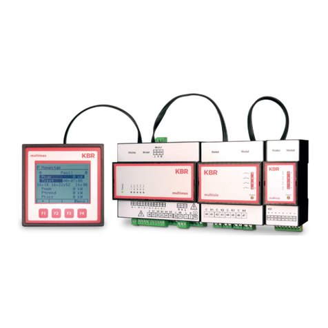
From left to right:
Display with function keys
multimax 3D6 basic module,
multisio relay module
multisio digital input module

KBR multimax 3D6
V3.00
EDEBDA0210-3313-1_EN
14
Installation
4 Installation
In this chapter, you will nd a description of:
„Device memory, battery-buered“
„Mounting the device“
„Connections“
4.1 Device memory, battery-buered
The device is equipped with an internal data memory, which is battery buered
to preserve long-term data. To prevent it from being discharged, this backup
battery (e.g. Varta CR 2032) is not built in when the device is delivered, but
included separately in the delivery.
Before the initial start-up of the device, please insert the backup battery rst (as
described in the following), as otherwise all stored data would be lost in case of
a power failure.
4.1.1 Inserting or replacing backup battery:
1. Disconnect the device from the supply voltage.
2. Lift the upper housing cover with a suitable tool (e.g. a small screwdriver).
3. When replacing a battery, remove the empty battery from the clamping
bracket with a tool.
4. Push the new battery into the clamping bracket and make sure that it is
inserted correctly and has the right polarity.
5. Put the rear housing cover back on and push it down until it clicks into place.
6. Reconnect the device to the supply voltage.
Caution

V3.00
KBR multimax 3D6
EDEBDA0210-3313-1_EN
15
When the battery is empty or has been removed, there is no supply voltage.
In this case, not only the storage data are lost, but the time settings have to be
reset as well!
4.2 Device installation
During installation, the applicable DIN / VDE regulations must be observed!
Before the device is connected to the power supply, you have to check whether
the local power supply conditions comply with the specications on the
manufacturer’s label. A faulty connection may destroy the system!
The device must be connected in accordance with the connection chart. For
energy and synchronous pulse input, polarity must be observed (contact your
energy supplier).
In systems susceptible to lightning, lightning protection must be provided for
the control voltage, bus line and pulse lines (e.g. energy supplier pulse lines
from the transformer station to the location of the energy control system).
4.3 Connections
To keep interfering pulses away from the inputs, a shielded cable must be used
for feeding energy and synchronous pulse, and for the connection to the PC
(e.g. J-2Y(St) Y 2x2x0.8 mm). (Shielding may only be connected to PE in the
vicinity of the main unit).
Terminals
1 (L) / 2 (N)
and PE
Power supply connection. The device is powered from the
auxiliary supply. For technical data please refer to the manu-
facturer’s label.
Terminal 90
(ground),
91 (A), and
92 (B)
Interface connection for communication at the Energy Bus
Installation
Caution
Caution

KBR multimax 3D6
V3.00
EDEBDA0210-3313-1_EN
16
Installation
Terminal40
(C)
Connection for voltage supply to the relay outputs
terminals 41 to 45
The relays for the control outputs share the same connection
to the supply voltage.
Terminals
41 (k1) to 45
(k5)
Wet relay contacts These contacts serve as controls outputs.
In a currentless state of the device, the contacts are opened
for stages that are not hooked up.
Maximum switching capacity of 2A at 250V AC
Terminal 30
(C)
Connection for voltage supply of the relay output terminal
31 (k6)
Terminal 31
(k6)
Dry relay contact. This contact serves as a message or alarm
output. During operation, an audible or visual message may
be activated, or a consumer shut down. The contact is open as
long as the device is currentless, and if there is an active mes-
sage. Maximum switching capacity of 2A at 250V AC
Terminals 80
and 81
Digital output
Terminals 50
to 59,
Digital inputs, for example for pulse counter
E1 E2 E3 E4 E5
80 81 50 51 52 53 54 55 56 57 58 59
Output
Ausgang
Inputs
Eingänge
Modul/
Module
OUT
multimax
40 41 4442 43 45 30 31 1 2 PE
Netz
Power
92 91 90
B A
T
ck1 k2 k3 k4 k5 c k6
Relais
Relay
Alarm-
Relay
F1
OUT
Display
zu weiteren Busteilnehmern
bzw. Leitungsabschluss /
to other bus devices
and line termination
Connection diagram
Terminal assignment
in acc. with factory
settings
= Digital output
E1 = Counter input 1
E2 = Counter input 2
E3 = Target value
switchover input
E4 = Tari change input
E5 = Measuring periods
synchronous pulse
input
40 = Control voltage input
41 = Relay output line 1
42 = Relay output line 2
43 = Relay output line 3
44 = Relay output line 4
45 = Relay output
prewarning contact

V3.00
KBR multimax 3D6
EDEBDA0210-3313-1_EN
17
multimax
Schriftarten
Myriad Pro Black 12 = Gerätename
Größe / Zuschneidung : 89,4 x 89,4 mm
Material / Beschaenheit : Acrylglas entspiegelt bedruckt; t = 3,0 mm
Druck : Spiegelverkehrt
Frontplattefarben : siehe Farbpalette oben
Schriftart Logo + F1 F2 F3 F4 : Grak
Sonstige Schriften : siehe Schriftarten oben
Index Änderung Datum Name
Strasser08.10.10
Farbpalette
Rot Pantone 199
Weißaluminium RAL 9006 (Silber)
Display-Fenster (farblos - transparent)
Erstellung
Frontplatte Bezeichnung:
EDV Bezeichnung:
Artikelnr.: EBLFPL 0068
Geprüft Datum
12.10.2010
FPV0010 multimax Display
Frontplattevorlage
Layout
ZMZFPV0010_4110-1_DE-GB_multimax 3D6-ESBSDS-5DI6RO1DO.ai
Blatt
1 / 2
A4Maßstab: 1 : 1
Strasser12.10.10
EDV Bezeichnung1.
5 Control and display panel
5.0 Description of buttons and displays, factory settings, setting
ranges
1 Display navigation panel
The navigation panel shows the main menu selected, considerably
simplifying operation of the device.
The operator can immediately see which menu he is in.
2 Unit display
The DOT matrix display is normally used to show measured values.
In some submenus, this display area is used to show additional information to
assist operation.
3 Hot key area
The text line corresponds to the function keys lying below it and is used to
issue messages and text. The interaction of key and accompanying display
enables convenient and self-explanatory operation.
1 Display naviga-
tion panel
2 Data display
3 Hot-key area
P actual
0 Ptarg
Pacc kW
Trem
12:30PM
12:40:23 M
12:45 M
Pact kW
Ptrend kW
Pcorr kW
menu

KBR multimax 3D6
V3.00
EDEBDA0210-3313-1_EN
18
Preprogramming (default settings)
I/O parameters
Basic module Function
Inputs E01 Pulse counter Terminals 50 and 51
E02 Pulse counter Terminals 52 and 53
E03 Target value switching NO contact Terminals 54 and 55
E04 Tari switching input NO contact Terminals 56 and 57
E05 Measuring period synchronous
pulse
NO contact Terminals 58 and 59
Outputs A01 Relay output Terminals 40 and 41
A02 Relay output Terminals 40 and 42
A03 Relay output Terminals 40 and 43
A04 Relay output Terminals 40 and 44
A48 Relay output prewarning contact NO contact Terminals 40 and 45
A49 Alarm relay NC contact, currentless
and opened in case of
error
Terminals 30 and 31
A50 Digital output Digital output Terminals 80 and 81
Module number
Input number
M00.1 Pulse counter E 01 inverse no
t Pact => 0 0 sec.
Pulse value 1 p./kWh
U primary 1V
U secondary 1V
I primary 1A
I secondary 1A

V3.00
KBR multimax 3D6
EDEBDA0210-3313-1_EN
19
Preprogramming (default settings)
Module number
Input number
M00.2 Pulse counter E 02 inverse no
t Pact => 0 0 sec.
Pulse value 1 p./kWh
U primary 1V
U secondary 1V
I primary 1A
I secondary 1A
M00.3 Digital input target value switch-
ing
E 03 not inverse
M00.4 Tari switching input E 04 not inverse, HT, if
active = LT
M00.5 Synchronous input E 05 not inverse
Module number
Output number
M00.6 Relay output A 01 not inverse ,
relay group 0
M00.7 Relay output A 02 not inverse ,
relay group 0
M00.8 Relay output A 03 not inverse ,
relay group 0
M00.9 Relay output A 04 not inverse ,
relay group 0
M00.10 Relay output prewarning contact A 48 not inverse ,
relay group 0
M00.11 Alarm relay A 49 inverse
M00.12 Digital output A 50 not inverse ,
relay group 0

KBR multimax 3D6
V3.00
EDEBDA0210-3313-1_EN
20
Setting range of the parameters
Parameters Setting ranges
General
parameters 1
TYPE oneValue, switching input, list of target values
Target value 1 0 to 50000 kW
Degree of optimiza-
tion
80% to 100%
Period duration 1, 10, 15, 30, 60 minutes
Switching interval 2 to 30 seconds
Synchronization Input, internal, bus, tari
General
parameters 2
Minimum value
monitoring
yes, no
Target value
tracking
o, month, year
Target value
tracking
0% to 100%
external correction
value
yes, no
Energy type 0 to 99
Unit kW, MW, m3/h
General
parameters 3
hidden for TYPE
one value
Target value 2 0 to 50000 kW
Address target value
2 - selection
E00 to E50
Address target value
3 - selection
E00 to E50
*Limit max. Pact 2 0 to 60000 kW
*Limit max. Pact 3 0 to 60000 kW
General
parameters 4
Tari switching bus, internal, input
Start LT 00:00 to 24:00
End LT 00:00 to 24:00
*Limit max. Pact 1 0 to 60000 kW
*LIM min. Pact 0 to 50000kW
Address *LIM relay
max. Pact
A41 to A47, A40 = deactivated
Address *LIM relay
min. Pact
A41 to A47, A40 = deactivated
*LIM = limit value
Table of contents
Other KBR Controllers manuals

KBR
KBR multicomp D6 7 Series User manual

KBR
KBR multicomp 4D6-ESBSDS-1V1C6RO Operating instructions

KBR
KBR multicomp F144-MS-1V1C1TI6DO6RO-3 Service manual

KBR
KBR multimax D6-5 Series User manual

KBR
KBR F144-3PH User manual

KBR
KBR F144-3PH User manual

KBR
KBR F144-MS-1V1C6-6RO-6DO-3 User manual

KBR
KBR multicomp D6 Series Instruction manual

KBR
KBR F144-MS-1V1C1TI6DO-3 Use and care manual

KBR
KBR Multicomp 2F144-NC-1V1C06RO Operating instructions