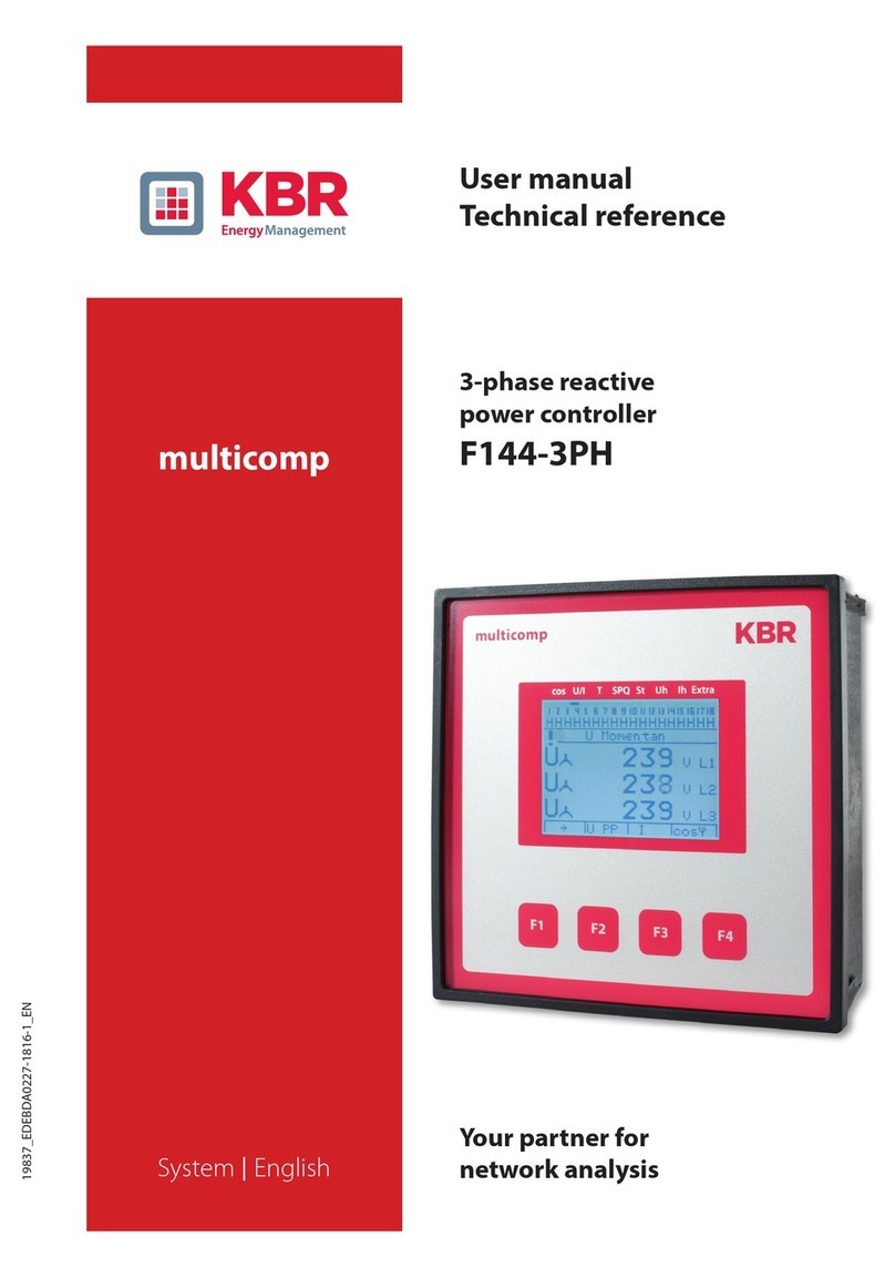
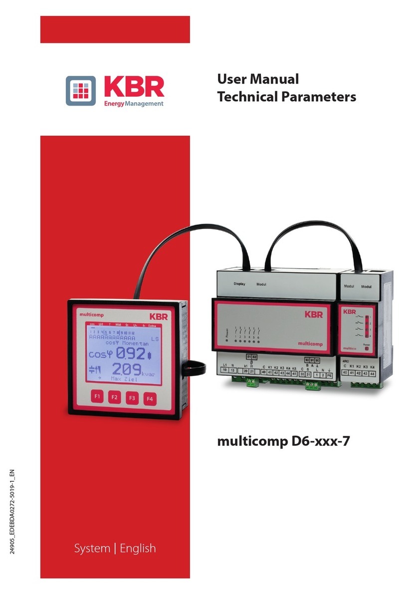
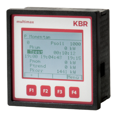
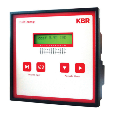
KBR F144-3PH User manual

19837_EDEBDA0227-2620-1_EN
User Manual
Technical Parameters
multicomp F144-3PH
System IEnglish

V2.00
19837_EDEBDA0227-2620-1_EN
2
1 Introduction........................................................4
1.1 User manual........................................................4
1.3 Safety notes ........................................................6
1.4 Product liability.....................................................6
1.5 Disposal ............................................................7
1.6 Overvoltage and lightning protection . . . . . . . . . . . . . . . . . . . . . . . . . . . . . . . 7
2 Description of functions of the multicomp F144-3PH ................8
3 Connecting the multicomp ........................................11
3.1 Installation and assembly ..........................................11
3.2 Current transformer connection: ...................................13
3.3 Connection diagram ...............................................14
3.4 Terminal assignment...............................................15
3.5 Default controller settings (default setting):.........................17
4 Control and display panel ..........................................20
4.1 Description of buttons and displays ................................20
4.2 Description of general settings: ....................................21
Table of contents
KBR Kompensationsanlagenbau GmbH does not accept any liability for any loss or dam-
age resulting from printing errors in or changes to this manual.
In addition, KBR Kompensationsanlagenbau GmbH does not accept any liability for any
loss or damage caused by defective devices or devices manipulated by the user.
Copyright 2020 by KBR Kompensationsanlagenbau GmbH
Subject to change.
Table of contents

V2.00
19837_EDEBDA0227-2620-1_EN
3
5 Commissioning guideline for the multicomp F144 -3-3PH...........22
5.1 Basic device conguration:.........................................24
5.2 Setting transformer ratio...........................................25
5.3 Operating Diagram ................................................27
5.4 Menu structure ....................................................28
5.5 Main menu cos φ ..................................................30
5.6 Main menu Voltage / Current.......................................32
5.7 Main menu Temperature ...........................................33
5.8 Main menu power .................................................34
5.9 Main menu stages .................................................35
5.10 Main menu Uh voltage harmonics..................................36
5.11 Sub menu THD voltage ............................................37
5.12 Main menu Ih current harmonics ...................................38
5.13 Sub menu ID current...............................................39
5.14 Main menu Extras .................................................40
5.15 Description of submenus ..........................................41
5.15.1 The Commissioning submenu contains the following items: ........41
5.15.2 The Settings submenu contains the following items: ................43
5.15.3 Reset of parameters: Reset to default settings (delivery state) .......47
6 Notes on Troubleshooting: .........................................50
7 System and Safety Device Maintenance ............................51
8 Technical data multicomp F144-3PH ...............................52
8.1 Measuring and display values . . . . . . . . . . . . . . . . . . . . . . . . . . . . . . . . . . . . . .52
8.2 Measuring accuracy ...............................................53
8.4 Device memory....................................................53
8.5 Power supply ......................................................53
8.6 Hardware inputs and outputs
8.6.1 Inputs .............................................................54
8.6.2 Outputs ...........................................................54
8.7 Electrical connection ..............................................55
8.8 Mechanical data ...................................................55
8.9 Standards and miscellaneous ......................................56
Table of contents

V2.00
19837_EDEBDA0227-2620-1_EN
4
1 Introduction
Thank you for choosing this KBR quality product.
To become familiar with the operation and programming of the device and to use the
full range of functions of this high-quality product at all times, you should read this user
manual carefully.
The individual chapters explain the technical details of the device and show how damage
can be avoided through proper installation and commissioning.
1.1 User manual
This user manual describes the device version multicomp F144-3PH. This user manual
must be accessible to the user at all times (e.g. in the switchgear cabinet). Even if the
device is resold to third parties, the manual remains an inherent part of the device.
Although the utmost care has been taken in writing this user manual, errors may still oc-
cur. We would be very grateful if you would notify us of any errors or unclear descriptions
you may notice.
Introduction

V2.00
19837_EDEBDA0227-2620-1_EN
5
1.2 Safety keys
This manual contains instructions that you must follow for your personal safety and to
avoid material damage. These instructions are identied by a warning sign or information
symbol, depending on the degree of hazard they warn about.
DANGEROUS VOLTAGE
"Warning" means that death, major injuries or damage may occur if suitable safety pre-
cautions are not taken.
CAUTION
"Caution" means that minor injuries or damage may occur if the appropriate safety pre-
cautions are not taken.
NOTE
"Note" is an important piece of information on the product, its operation or the respec-
tive part of the user manual to which special reference is being made.
Disclaimer
The contents of these ouser manual have been carefully reviewed in terms of the hard-
ware and software described. However, deviations cannot be excluded and therefore
complete conformity cannot be guaranteed. The specications made in this user manual
are reviewed on a regular basis; any corrections required will be included in the next
revision.
Introduction

V2.00
19837_EDEBDA0227-2620-1_EN
6
1.3 Safety notes
In order to prevent operating errors, device operation is kept as simple as possible. This
will enable you to start your device up quickly.
It is in your own interest to read the following safety instructions carefully. The applicable
DIN/VDE regulations must be observed during installation!
Power supply connection, setup and operation of the device must be performed by
qualied personnel only. Qualied personnel as dened in the safety notes in this user
manual are those authorized to set up, ground and mark devices, systems and circuits in
accordance with applicable standards and regulations.
To prevent re and electric shock, do not expose the device to rain or moisture!
Before connecting the device to the power supply, check whether the local power supply
conditions comply with the specications on the device nameplate.
CAUTION
Incorrectly connecting the device can damage it.
For device connection, the data given in the connection diagram must be complied with
(see chapter “Connection diagram”) and the connection lines must be voltage-free. When
wiring, always ensure that all wiring material used is neither damaged nor defective and
that the polarity is correct!
Proper and safe operation of the product requires correct transport, storage, installation
and assembly as well as careful operation and maintenance.
If the device has any visible damage it is considered unt for use and must be disconnect-
ed from the mains!
Troubleshooting, repairs and maintenance work may only be carried out at our plant or
after contacting our customer service team. If the device is opened without authoriza-
tion, any warranty or guarantee claim is forfeited. Correct functioning can no longer be
guaranteed!
Opening the device may expose live parts. Capacitors in the device may still be charged,
even if the device has been disconnected from all power sources. Do not operate open
devices under any circumstances!
Systems that are at risk from lightning strikes must feature lightning protection for all
input and output lines.
1.4 Product liability
You have purchased a high-quality product. Only top-quality components with excep-
tional reliability are used.
Introduction

V2.00
19837_EDEBDA0227-2620-1_EN
7
Each device undergoes a long-term test before delivery.
With regard to product liability, please see our general terms and conditions for electron-
ic devices, which you can read at www.kbr.de.
The warranty on device characteristics only applies if the device is operated in accor-
dance with its intended use!
1.5 Disposal
Please dispose of defective, out-of-date or no longer used devices properly.
If required, we will dispose of the device for you.
1.6 Overvoltage and lightning protection
To protect your purchased high-quality devices from damage, we strongly recommend
that you take overvoltage protection measures. Protect control voltage inputs, pulse and
bus lines.
Introduction

V2.00
19837_EDEBDA0227-2620-1_EN
8
Functions
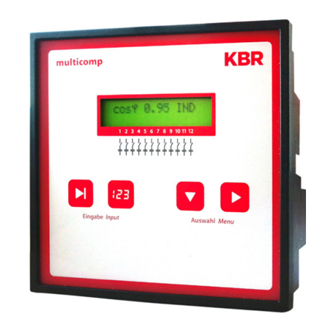
2 Description of functions of the multicomp F144-3PH
The multicomp F144-3PH reactive power controller works automatically in 4-quadrant
operation (generator operation), i.e. even with energy recovery to the utility company
network, missing compensation power is detected without a problem and compensated.
The control type of the device is optimizing, i.e. the controller selects the switching stage
with the suitable compensation capacity according to the missing compensation power.
By using the "maximum switching power per switching operation" parameter (menu
Extra / Commissioning / max. switching power), you can dene how many kvar the
controller can switch (on and o) at the same time. This enables faster compensation. If
the set value is smaller than the largest switching stage available, the value of the largest
stage is automatically used as the switching criterion.
Through the integrated temperature measurement input, the ambient temperature in
the reactive power compensation system is also monitored and if a predened limit tem-
perature is exceeded, the fan is switched on. Furthermore, you can protect the system by
setting an alarm / switch-o temperature which switches it o if there is a risk of damage
due to overtemperature.
The controller is additionally equipped with a limit monitoring function for protection of
capacitors from overvoltage and excessive harmonic load of voltage and current.
The 3-phase voltage and current recording makes it possible to not only realize 3-phase
compensation as before, but also real single-phase compensation (balancing) or a mix-
ture of single-phase and 3-phase compensation.
In this context, it is possible to separately congure 3-phase, phase-phase and sin-
gle-phase stages for each of the 18 existing compensation stages.
Furthermore, it is also possible to operate a compensation system with capacitive stages
only, inductive stages only or in mixed mode.
For 3-phase measurement, the measuring values are displayed separately per phase,
making it possible to evaluate the actual power supply conditions in detail. For sin-
gle-phase measurement, the measuring values of the phase measured are displayed but
the power values are additionally projected as total power.
By using an additional digital input, it is possible to activate a second deviating target
CosPhi.
Furthermore, the device is equipped with a RS485 bus interface for operation at the KBR
eBus with the visual energy computer software. This enables comfortable visualization of
the measuring values and the controller's operating state as well as convenient congu-
ration of the device via the primary control unit.
V2.00
19837_EDEBDA0227-2620-1_EN
9
Functions
Alternatively, this serial interface can also be accessed via Modbus (RTU). A detailed de-
scription can be found in the “Modbus data point description,” available separately.
Please also observe the following notes on start-up and operation:
In case of operation in a 3-wire network, a zero-point creator is required (e.g. 700/100 V
AC, primary 3-phase connection, available from KBR), as the controller needs a neutral
conductor for trouble-free operation.
For operation as a single-phase measuring controller, the measuring current must always
be connected at the terminals 20 und 21 (k1 and l1). After changing to single-phase oper-
ation, you can congure the phase shift between the measuring current and measuring
voltage (menu Commissioning / Transformer / Main current transformer).
In this case, the measuring voltage must be connected to terminals 10 (L1) and 13 (N).
For this operating mode, the compensation system only may have 3-phase stages, as
single-phase measurement is projected to 3-phase operation.
If the measuring current is taken from a phase other than the measuring voltage, this
shift can be adjusted under the menu item Extra / Commissioning / Transformer / Main
current transformer / Phase I (0°, 120°,240°)
The following settings are possible:
U L1, I
L1 =0° U L2, I
L2 =0° U L3, I
L3 =0°
U L1, I
L2 = 120° U L2, I
L3 = 120° U L3, I
L1 = 120°
U L1, I
L3 = 240° U L2, I
L1 = 240° U L3, I
L2 = 240°

V2.00
19837_EDEBDA0227-2620-1_EN
10
Installation
NOTE
A phase-phase measurement (2 measuring phases without neutral conductor) is not
possible with this device.
NOTE
For mixed operation of contactor stages and thyristor stages of the same size, the thyris-
tor stages should be assigned to the stages in the back, as the front stages are switched
rst. The thyristor stages are detected if the discharge time set is under 1 second.
After 60 seconds, an active thyristor stage is replaced by a comparable contactor stage (if
available) for continuous operation. This way, quick compensation is guaranteed even in
case of fast load changes.
For mixed operation of phase-phase and phase-N stages, the largest phase-N stage must
not be larger than the largest phase-phase stage. The smallest single-phase stage should
only be half the size of the smallest phase-phase stage.
For mixed operation of phase-N stages and 3-phase stages, the largest 3-phase stage
must be larger than the combination stage consisting of phase-N stages.
For mixed operation of phase-phase-phase stages and 3-phase stages, the largest
3-phase stage must be larger than the combination stage consisting of phase-phase
stages.
For single-phase compensation (only phase-N stages or only phase-phase stages),
3-phase measurement needs to be programmed

V2.00
19837_EDEBDA0227-2620-1_EN
11
Connection
3 Connecting the multicomp
3.1 Installation and assembly
The applicable VDE regulations must be observed during installation!
Before the device is connected to the power supply, check whether the local power
supply conditions comply with the specications on the nameplate. Incorrect connec-
tion may result in the destruction of the device. A dierent power frequency inuences
the measurement accordingly.
The device must be connected in accordance with the connection diagram.
The power supply input of systems that are at risk from lightning strikes must be
equipped with suitable lightning protection.
CAUTION
The control voltage as well as the applied measuring voltage of the device must be pro-
tected by means of a back-up fuse.
When connecting the current transformers, the energy ow direction and the correct
assignment to the voltage path must be observed!
NOTE
When connecting the phase (L1) to terminal 1 and the neutral conductor (N) to terminal 2
(Ph-N100V – 240V+/-10 % 50Hz/ 60 Hz/DC) the safety device and the disconnector in the
supply line to terminal 2 (N) are not required.
The safety device and the disconnector to terminal 2 (N) are only required for the follow-
ing connection variants:
Alternating voltage:
Terminal 1 (L1) and terminal 2 (L2):
US1 Phase-Phase 100V - 240V +/-10% 50Hz/60 Hz
Direct voltage:
Terminal 1 (+) and terminal 2 (-):
US1 100V - 240V +/-10% DC
Connection variants of the power supply

V2.00
19837_EDEBDA0227-2620-1_EN
12
Connection
Terminal 1 Terminal 2
Voltage Safety device
and disconnector
to Terminal 2
required
Power supply unitUS1
Phase
L
Neutral
conductor
N
100V - 240V +/-10% AC
50/60 Hz No
Phase
L1
Phase
L2
100V - 240V +/-10% AC
50/60 Hz Yes
+ - 100V - 240V +/-10% DC Yes

V2.00
19837_EDEBDA0227-2620-1_EN
13
Connection
3.2 Current transformer connection:
When mounting the transformer, observe the direction of the current or energy ow. If
the current transformer is mounted the wrong way, the measured current value will be
negative.
A prerequisite for this is that energy is supplied to the device.
The following points must be observed when connecting the device:
Direction of the energy ow
Assignment of measuring voltage input / current transformer input
The current transformer on terminal 20/21 (k1/l1) must be installed in the phase in which
the measuring voltage for terminal 10 (L1) is measured.
The device will display positive current when connection
and energy ow direction are correct.
If connected incorrectly, the current displayed is negative.
Interchange the connections until the display shows correct values.

V2.00
19837_EDEBDA0227-2620-1_EN
14
Connection
3.3 Connection diagram
F1
Trenn-
vorrichtung/
circuit breaker
F2
Hinweis beachten!
read information!
L1
L3
L2
N
Stromussrichtung / current direction
Netz*
Power
L N
1 2 11
L2
Messspannung
Measuring voltage
L1
10 13
L3 N
12
25
L3
Messstrom
Measuring current
k1
20 23
L2k2L1
2221
k3
24
CK2 K3 K4 K5 K6
41 42 43 44 45 46
40
K1
CK14 K15 K16 K17 K18
55 56 57 58 59 60
54
K13
CK8 K9 K10 K11 K12
48 49 50 51 52 53
47
K7
90 91 92
A B
BUS
39 70 71
38
cosphi 2
++
Temperaturfühler
temperature probe
Relay 2:
Kontakt geöffnet bei
fehlender Spannungs-
versorgung und bei
Alarm!
Contact is open by
no power and alarm!
Schaltstufen / stages
Relay 1 Relay 2
33
30 3231
Lüfter
fan
Alarm
alarm
ϑ

V2.00
19837_EDEBDA0227-2620-1_EN
15
3.4 Terminal assignment
Connection
Terminal:
1 (L) and 2 (N):
Power supply connection
A control voltage is required to supply the device with pow-
er. The unit is equipped with a multi-range power supply and
may be supplied by voltages 100V – 240V+/ -10% 50Hz/60
Hz (see nameplate for device voltage).
Terminal:
10 (L1)
11 (L2)
12 (L3)
13 (N):
Voltage measuring input
Input voltage both as PH-N and PH-PH measurement.
3-phase or single-phase measurement for 25... 230...280V
AC PH-N, 50/60 Hz. The measuring range is congurable. For
higher voltages, connection via voltage transformers is nec-
essary (medium voltage measurement x/100 V), measuring
range from 500V to 30.0 KV Ph-Ph.
20 (k1) and 21 (l1)
22 (k2) and 23 (l2)
24 (k3) and 25 (l3):
Current measurement inputs
The measuring input for current must be connected via a
current transformer x/1A AC or x/5A AC. When connecting
the transformer, pay attention to the energy ow direction
and the correct assignment of measuring voltage inputs to
the current transformers.
30 and 31: Floating relay contact
The contact serves as switching output for the fan control.
Maximum switching capacity 2A at 250V AC.
32 and 33: Floating relay contact
This contact serves as a message or alarm output. During
operation, an acoustic or visual message can be activated or
a consumer switched o using this relay. The contact is open
as long as the device is dead as well as when there is an
active message. Maximum switching capacity 2A at 250V AC.

V2.00
19837_EDEBDA0227-2620-1_EN
16
Connection
40 (C):
47 (C):
54 (C):
Connection for voltage supply to the
relay output terminals 41 to 46
Connection for voltage supply to the
relay output terminals 48 to 53
Connection for voltage supply to the
relay output terminals 55 to 60
The relays for the load contactor control outputs share the
same connection to the supply voltage.
41 (K1) to 46 (K6)
48 (K7) to 53 (K12)
55 (K13) to 60 (K18):
Non-oating relay contacts
These contacts serve as control outputs for the load con-
tactors of the compensation stages. The contacts are open
as long as the device is dead and in stages that are not con-
nected. Maximum switching capacity 2A at 250V AC.
38 (+) and 39 (-): Input for oating relay.
This input serves as switching input for the target cos phi.
During operation, you can switch from target cos phi 1 to
target cos phi 2. When connecting an electronic switch,
please make sure to observe polarity.
70 (+) and 71 (-): Temperature sensor input
A temperature sensor, e.g. PT1000, can be connected to
this input to measure the switchgear cabinet temperature.
Temperature measuring range from -10°C to +60°C.
90 (ground)
91 (A)
92 (B):
Interface connection
For KBR-eBus or Modbus communication.

V2.00
19837_EDEBDA0227-2620-1_EN
17
Connection
3.5 Default controller settings (default setting):
Methods of measurement 3-phase
Commissioning:
Measuring voltage transformer Primary voltage 400 V Ph-Ph
Secondary voltage 400 V Ph-Ph
Zero-point creator o
Main current transformer Primary current 1000 A
Secondary current 5 A
Rot.eld I 0° (for single-phase measurement)
Consumption target CosPhi 1 0.95 inductive
Consumption target CosPhi 2 0.95 inductive
Recovery target CosPhi 1.00
Alarm CosPhi 0.92 inductive
Stage power not set
Discharge time 60 seconds
Type of connection 3-phase
Type of stage Capacitor stage
Max. switching capacity per switching
operation
1 kvar or largest
programmed stage power
Display (unaected by reset):
LCD contrast 50%
LCD brightness 60%
Dimming time 15minutes
Dimming brightness 0%

V2.00
19837_EDEBDA0227-2620-1_EN
18
Connection
Basic system parameters switching performance:
Hysteresis connection 100% of lowest stage power
Hysteresis switch-o 100% of lowest stage power
Alarm delay 1200 seconds (20 minutes)
Idle time: 10 seconds
Switching interval: 8 seconds
Current attenuation coecient: 2
Voltage attenuation coecient: 2
Attenuation coecient Qmiss: 2
Basic system temperature parameters:
Measurement active
Switching thresholds
Fan switched on 28°C
Fan switched o 23°C
Stages switched on 43°C
Stages switched o 48°C
Basic system limit parameters:
Operating cycle limit 80000 connections
Operating cycle count Activated by set limit
Overvoltage limit 440 VAC PhPh (corresponds to 10 %)
Current low load limit 10 A
Average current limit: 6-Fold current
transformer ratio
Limit THD 8%
Activated by set limit
Limit Id 20 %
Harmonics monitoring Activated by set limit

V2.00
19837_EDEBDA0227-2620-1_EN
19
Control and display panel
Miscellaneous:
Sampling rate Automatic
Error message dialog In case of any errors, message
and alarm relay
Service:
Password No password (9999, meaning all functions
are accessible)
NOTE
LCD parameters, sampling rate, password, bus parameters and language settings are
unaected by reset.
Error message dialog:
No stage power: Message and alarm relay
Power failure: Message and alarm relay
Reset performed: Message and alarm relay
Temperature switch-o of stages Message and alarm relay
No measuring current: Message and alarm relay
No measuring voltage: Message and alarm relay
Low load operation: Message and alarm relay
Harm. limit U exceeded: Message and alarm relay
Harm. limit I exceeded: Message and alarm relay
Operating cycle limit exceeded: Message and alarm relay
Overvoltage limit exceeded Message and alarm relay
Average current limit exceeded Message and alarm relay
Facility too small: Message and alarm relay

V2.00
19837_EDEBDA0227-2620-1_EN
20
Control and display panel
cos Ó actual
cosÓ 0.64
22.4 kvar
®Qf cosÓ
Display
navigation panel
Measured value
display
Hotkey area
1 2 3 4 5 6 7 8 9 10 11 12 13 14 15 16 17 18
AAAAA A A A AA A AA A A A AA
4 Control and display panel
4.1 Description of buttons and displays
1 Display navigation panel
The navigation panel shows the main menu selected, considerably simplifying operation
of the device. The operator can immediately see what menu he is in.
2 Measuring value display
The DOT matrix display is normally used to show measured values. In some submenus,
this display area is used to show additional information to assist operation.
3 Hot key area
The text line corresponds to the function keys below it and is used to issue messages and
text. The interaction between key and corresponding display ensures user-friendly and
self-explanatory operation.
Operating messages for individual switching stages:
1 = switching stage number
A = switched on in automatic operation
1 = switching stage number
= switched o in automatic operation
1 = switching stage number
H = switched on in manual operation
1 = switching stage number
0 = switched o in manual operation or no stage power is programmed
Other manuals for F144-3PH
1
Table of contents
Other KBR Controllers manuals

KBR
KBR multicomp F144-MS-1V1C1TI6RO6DO-3 User manual

KBR
KBR F144-MS-1V1C6-12DO-3 User manual

KBR
KBR F144-MS-1V1C6-6RO-6DO-3 User manual

KBR
KBR multicomp F144-NC-1V1C6DO6RO-2 Use and care manual

KBR
KBR F144-3PH User manual

KBR
KBR multicomp D6 7 Series User manual

KBR
KBR multicomp F144-MS-1V1C1TI6RO-3 User manual

KBR
KBR F144-MS-1V1C1TI6DO-3 Use and care manual

KBR
KBR multicomp F144-MS-1V1C1TI6DO6RO-3 Service manual

KBR
KBR multicomp 4D6-ESBSDS-1V1C6RO Operating instructions