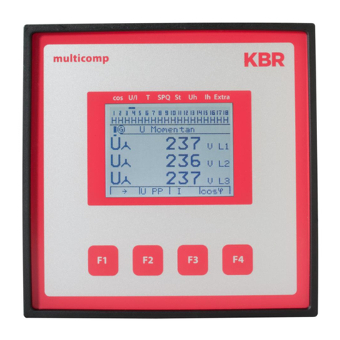
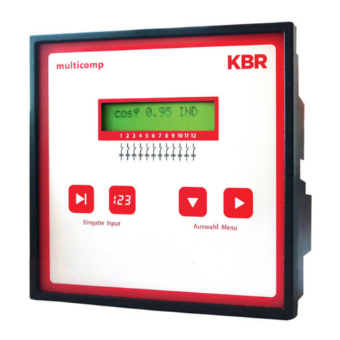
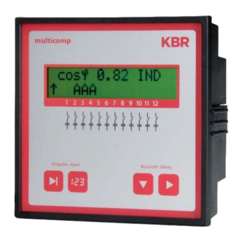
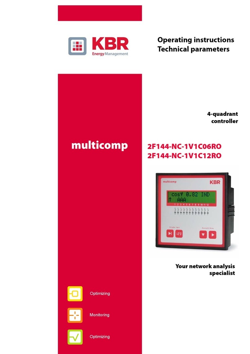
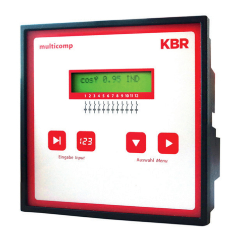
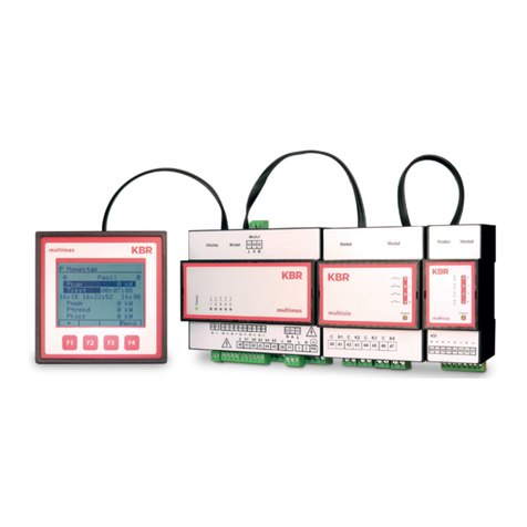
KBR multicomp F144-MS-1V1C1TI6DO6RO-3 Service manual

22586_EDEBDA0253-0318-1_EN
Technical reference
Your partner for
network analysis
4-quadrant controller
F144-MS-1V1C1TI6DO6RO-3
multicomp
System IEnglish

2
KBR multicomp F144-3 6DO/6RO
© KBR Kompensationsanlagenbau GmbH
Misprints, printing errors
and technical changes reserved

Rev. 1.00 3
22586_EDEBDA0253-0318-1_EN
KBR multicomp F144-3 6DO/6ROTable of contents
1 Functional principle
of the controller...................................8
2 Control and display panel............. 11
3 Setting range of the
congurable parameters:.............. 14
4 Installation and electrical connec-
tion of the system ............................ 16
4.1 General, very important
information......................................... 16
4.2 Current transformer connection
and measuring voltage.................. 17
4.3 Current transformer dimensions 17
4.4 Standard connection diagrams .. 17
5 Commissioning the system.......... 20
5.1 General notes on commissioning20
6 Navigation and device displays .. 22
7 Device displays of the
main menus ....................................... 24
8 Description of the individual
display windows............................... 26
8.1 Initialization window: ..................... 26
8.2
Commissioning window if no
stage power is programmed ..........26
8.3 Start menu window:........................ 30
8.4 Stage state window:........................ 31
8.5 Service window: ............................... 32
8.6 Commissioning window:............... 33
8.7 Switching performance
window:............................................... 36
8.8 Error message window: ................. 38
8.9 Extras window................................... 39
9 Notes on troubleshooting ............ 42
10 System and safety
device maintenance........................ 43
11 Technical data.................................... 44
11.1 Measuring and display values..... 44
11.2 Measuring accuracy ........................ 45
11.3 Measuring principle ........................ 45
11.4 Device memory................................. 45
11.5 Other limits:........................................ 45
11.6 Power supply ..................................... 45
11.7 Hardware inputs and outputs ..... 46
11.7.1 Hardware inputs............................... 46
11.7.2 Hardware outputs ........................... 46
11.8 Electrical connection ...................... 47
11.9 Mechanical data ............................... 48
11.10 Standards and miscellaneous...... 48
12 Selection of cables and fuses....... 49
13 Data point description
for the Modbus protocol ............... 50
multicomp F144-3 ........................... 50
13.1 Modbus
commands supported.................... 51
13.2 Data formats ...................................... 51
13.3 Interface parameters....................... 54
13.4 Device settings.................................. 54
13.5 Data points......................................... 60
13.6 Device information.......................... 63
Rev. 1.00
22586_EDEBDA0253-0318-1_EN
4
KBR multicomp F144-3 6DO/6RO Introduction
Dear customer
Thank you for choosing a KBR product.
To familiarize yourself with operation and conguration of the device, we recommend
that you read this manual carefully. This will enable you to make use of the entire range of
functions that this high-quality product oers.
The individual chapters serve to explain the technical details of the device and show how
to properly install and start up the device to prevent damage.
This user manual is included in the scope of delivery of the device and must be accessible
to the user at all times (e.g. in the switchgear cabinet). Even if the device is resold to third
parties, the manual remains an inherent part of the device.
Although the utmost care has been taken in putting together this user manual, errors
may still occur. We would be very grateful if you could notify us of any errors or unclear
descriptions you may notice. The form included in the appendix to this manual can be
used to send us corrections or suggested improvements.
Yours sincerely,
KBR GmbH Schwabach

Rev. 1.00
22586_EDEBDA0253-0318-1_EN
5
KBR multicomp F144-3 6DO/6ROIntroduction
These operating instructions contain notes that must be observed for your
personal safety and to avoid damage to equipment. These instructions are
identied by a warning sign or information symbol, depending on the degree
of hazard they represent.
DANGEROUS VOLTAGE
means that death, major injury or substantial property damage may occur if the
appropriate safety measures are not taken.
CAUTION
means that minor injuries or property damage may occur if the appropriate
safety precautions are not taken.
NOTE
is an important piece of information on the product, product handling or the
respective part of the user manual to which special reference is made.
Disclaimer
The contents of this manual have been checked with the described hardware
and software components. However, deviations may occur so that no guar-
antee can be made for complete agreement with the documentation. The
specications given in this manual are checked on a regular basis; necessary
corrections will be included in the next revision.
We appreciate your corrections and comments.

Rev. 1.00
22586_EDEBDA0253-0318-1_EN
6
KBR multicomp F144-3 6DO/6RO Introduction
Safety notes
In order to prevent operating errors, handling of the device has been kept as
simple as possible. This will enable you to use the device very quickly. In your
own interests, however, we recommend you read the following safety instruc-
tions carefully.
DANGEROUS VOLTAGE
The applicable DIN/VDE regulations must be observed for installation!
Power supply connection, setup and operation of the device may only be
performed by qualied personnel. Qualied personnel as dened in the safety
notes in this user manual are personnel with electrical engineering qualica-
tions, knowledge of the national accident prevention regulations and safety en-
gineering standards as well as of the installation, commissioning and operation
of the device.
To reduce the risk of re or shock hazard, the device must not be exposed to
rain or humidity!
Before connecting the device to the power supply, check whether the local
power supply conditions comply with the specications on the device name-
plate.
A faulty connection may result in the destruction of the device!
When connecting the device, ensure that the data given in the connection
chart is complied with (see "Connection diagram") and that the connection
cables are not live. When wiring, always ensure that all wiring material used is
neither damaged nor defective and that the polarity is correct!
In order to ensure proper and safe product operation, ensure that the device is
transported, stored, installed and assembled and carefully operated and main-
tained in accordance with the specications.
If the device is visibly damaged it should generally be considered unsuitable
for use and disconnected from the power supply. Troubleshooting, repairs and
maintenance work may only be carried out in our facilities or after contacting
our service team.
Unauthorized opening of the the device will render your warranty null and
void. Correct operation can no longer be guaranteed!
Opening the device may expose live parts. Capacitors in the device may still be
charged, even if the device has been disconnected from all power sources. Do
not operate open devices under any circumstances!
Systems that are at risk from lightning strikes must be tted with lightning
protection for all input and output cables (see the "Protective measures" chapter
for recommendations).

Rev. 1.00
22586_EDEBDA0253-0318-1_EN
7
KBR multicomp F144-3 6DO/6ROIntroduction
Product liability
You have purchased a high-quality product.
We only use components of the highest quality and maximum reliability.
Each device is subjected to long-term testing before it is delivered.
For details on product liability, please refer to our
general terms and conditions for electronic equipment.
The assured device properties only apply if
the device has been operated in accordance with its intended use!
Disposal
Devices that are faulty, obsolete or no longer in use must be disposed of prop-
erly.
If required, we will dispose of the devices for you.

Rev. 1.00
22586_EDEBDA0253-0318-1_EN
8
KBR multicomp F144-3 6DO/6RO Functional principle
1 Functional principle of the controller
The multicomp F144-1V1C6DO6RO-3 hybrid controller has 12 outputs to
control capacitive compensation stages. Outputs 1 to 6 are designed to control
thyristor modules (by optocoupler outputs) and outputs 7 to 12 to control
capacitor contactors (by oating relay contacts).
To make optimal use of the thyristor modules' or capacitor contactor modules'
switching performance, you can set the following parameters separately:
for thyristor stages
Switching interval 50 to 9999 milliseconds
Discharge time 20 to 9999 milliseconds
Idle time 20 to 9999 milliseconds
for contactor stages
Switching interval 0 to 10 seconds
Discharge time 0 to 900 seconds
Idle time 0 to 300 seconds
The controller's microprocessor records the mains voltage and current con-
sumption of the entire plant by measuring transformer inputs (A/D converter)
and, on the basis of this, calculates the active and reactive power ratio of the
power supply. The controller operates in four quadrants.
Energy recovery in generator operation is detected and indicated by a "G"
ashing on the LCD display. While in generator operation, compensation to
cos phi 1.00 (output cos phi) is performed. To prevent alternating switching
operations, this target cos phi is maintained for 15 minutes after generator
operation ends.
The compensated power required for the target cos phi is calculated contin-
uously. If the power dierence corresponds to the set hysteresis (switch-on
and switch-o hysteresis), the stages are switched depending on the required
compensation power. Manually switched stages are, however, not included in
the optimization. In case of identical stages with identical power, the stage that
has been switched o for the longest time is switched on.
Having fewer switching operations results in optimum adjustment. Even for
large systems, sensitive controls can be set up with just a few modules. Stage
ratios do not need to be considered. After compensation, switching operations
are interrupted for a congurable time. To prevent alternating switching opera-
tions, you can increase the stage switch-o delay by up to 150% of the smallest
stage's power.
In light load operation (secondary measuring current under the limit), the stag-
es are switched o after the set delay time.

Rev. 1.00
22586_EDEBDA0253-0318-1_EN
9
KBR multicomp F144-3 6DO/6RO
After an adaption time of 60 seconds, the thyristor stages are switched by
contactor stages of the same size. This guarantees that the fast control charac-
teristics can be kept.
The integrated temperature measurement input monitors the temperature in
the reactive power compensation system and causes the fan to be switched on
if a predened temperature threshold is exceeded and switched o again when
the temperature drops below the reset temperature.
To prevent the fan from switching unnecessarily often, it has a run-on time
of 30 minutes. You can switch the fan (relay output 12) on or o permanently
using the "Stage status" menu. If you select "Auto", the fan output is controlled
by the temperature measuring input.
You can also protect the system by dening a switch-o temperature. This
makes it possible to switch stages o in time if there is a risk of damage due
to overheating. Once the temperature drops below the reset temperature, the
stages are switched on again one after the other.
The settings are saved on an EEPROM so that they are not lost in the event of a
power failure.
The measuring cycle of the controller used to record the necessary network
parameters takes approx. 20 ms.
NOTE
Limit for overvoltage switch-o = measuring voltage + 10% (taking the mea-
suring voltage ratio into account). This value cannot be changed and serves to
protect the compensation system.
In the event of an error, the compensation stages are switched o and "Over-
voltage" is displayed.
Functional principle

Rev. 1.00
22586_EDEBDA0253-0318-1_EN
10
KBR multicomp F144-3 6DO/6RO
CAUTION!
The discharge times are automatically predened, in the capacitor contactor
stage, for the following programmed stage powers. However, these must be
checked and corrected if they dier from the capacitor specications.
Capacitor power Discharge resistance Discharge time
0.1 kvar – 9.9 kvar 300 kOhm 60 seconds
10 kvar – 19.9 kvar 300 kOhm 120 seconds
20 kvar and above 300 kOhm 180 seconds
In the thyristor stages, irrespective of the stage power, the discharge time is al-
ways entered as 20milliseconds, both when reprogramming and when chang-
ing the stage power. A discharge time changed later on is retained however, as
long as the stage power is not changed.
Functional principle

Rev. 1.00
22586_EDEBDA0253-0318-1_EN
11
KBR multicomp F144-3 6DO/6RO
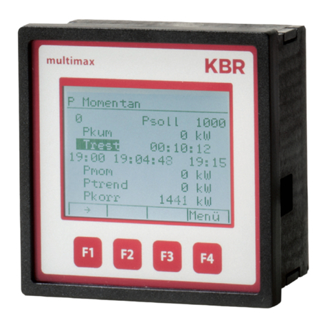
2 Control and display panel
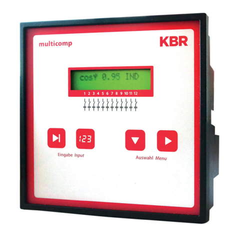
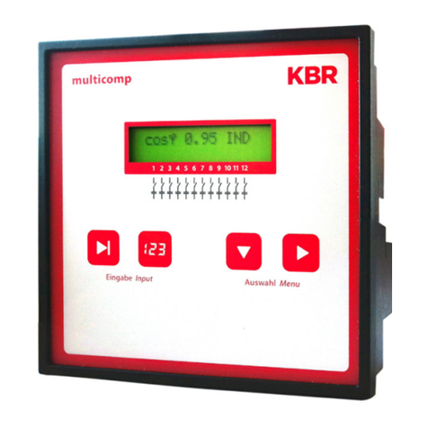
multicomp F144-MS-1V1C1TI6DO6RO-3
Operating elements:
1 LCD displaying the current status and user prompts
2 Number of possible controller output lines
3 Two sensor buttons for parameter conguration
4 Two sensor buttons for menu selection
1
2
3 4
General notes on operating the sensor buttons:
Ubutton Start conguration and reset input
Vbutton Change values during conguration
Wbutton Navigate through submenus
Xbutton Navigate through main menus and save button during con-
guration
Button combinations:
Uand VDelete accumulated values and reset the system
Control and display panel

Rev. 1.00
22586_EDEBDA0253-0318-1_EN
12
KBR multicomp F144-3 6DO/6RO Control and display panel
Default controller settings after reset:
Consumption target cos phi: 0.95 inductive
Recovery target cos phi: 1.00 (cannot be changed)
Alarm cos phi: 0.92 inductive
Main transformer current: Primary current 1000 A
Secondary current 5 A
Measuring voltage: Primary voltage 400 V Ph-Ph
(corresponds to 230V Ph-N )
Secondary voltage 400 V Ph-Ph
(corresponds to 230V Ph-N )
Rot. eld U: L1-N
Rot. eld I: L1
Current attenuation coecient: 0
Voltage attenuation coecient: 0
Attenuation coecient Qmiss: 0
Alarm delay: 20 minutes (1200 s)
Thyristor idle time: 30 ms
Contactor idle time: 30 seconds
Thyristor switching interval: 50 ms
Contactor switching interval: 8 seconds
Hysteresis connection: 100% of lowest stage power
Hysteresis switch-o: 100% of lowest stage power
Contactor stage operating cycle limit: 80000
Operating cycle count: active
Stage switching mode: Automatic
Sampling rate: Automatic
Harmonics monitoring: Activated by set limit
Limit THD: 8%
Stage power: Not set
Max. stage power per switching cycle: 0 kvar
Thyristor discharge time: 20 ms
Contactor discharge time:180 seconds
Password: No password (9999, meaning all functions
are accessible)
Language display: English
Contrast setting: 5
Brightness setting: 5
Dimmer brightness: 0
Light load limit: 15 mA
Light load delay: 60 minutes

Rev. 1.00
22586_EDEBDA0253-0318-1_EN
13
KBR multicomp F144-3 6DO/6ROControl and display panel
Temperature measurement: On
Output 12 as stage or fan: Fan output
Fan switch-on temperature: > 28 °C
Fan switch-o temperature: < 23 °C
System switch-o temperature: > 48°C
System switch-on temperature: < 43°C
Learning mode menu display: O
Touch tones: On
Error message dialog after reset:
No measuring voltage: Message and alarm relay
No stage power: Message and alarm relay
PFC too small: Message and alarm relay
THD too high: Message and alarm relay
Operating cycle limit exceeded: Message and alarm relay
No measuring current: Message and alarm relay
light load operation: Message and alarm relay
Temperature switch-o: Message and alarm relay
The controls in the compensation systems are preset.
The following parameters need to be checked or set:
Target cos phi in accordance with the electricity supplier regulations (for kVA
tari cos phi = 1)
Primary current and secondary current in accordance with input current
transformer.
Voltage transformer ratio, if required
NOTE
Upon delivery, the bus protocol is set to: Modbus RTU, baud rate 38400, parity
even
This setting can only be changed manually on the device.
Performing a "Reset to default settings" has no eect on changed settings.

Rev. 1.00
22586_EDEBDA0253-0318-1_EN
14
KBR multicomp F144-3 6DO/6RO
3 Setting range of the
congurable parameters:
Stage state:
Stage switching mode Automatic, Manual o, Manual on
Commissioning:
Password 4 digits, numerical, no password = 9999
(meaning all functions are accessible)
Primary current 1 A to 999999A
Secondary current 1 and 5 A
Consumption target cosφ ind. 0.80 to cap. 0.80
Recovery target cosφ ind. 1.0 (cannot be congured)
Primary voltage 1 V to 999999 V Ph-Ph
Secondary voltage 1 V to 999 V Ph-Ph
Thyristor stage discharge time 20 to 9999 ms
Contactor stage discharge time 0 to 900 seconds
Max. stage power per
switching cycle 0 to 9999 kvar
Rot. eld U L1N, L2N, L3N, L12, L23, L31
Rot. eld I L1, L2, L3, -L1, -L2, -L3
Stage power learning mode Yes, No
Stage power 0 to 999.9 kvar
Switching performance:
Hysteresis connection 70 to 150 %
Hysteresis switch-o 70 to 150 %
Alarm relay time 3 to 3000 sec.
Thyristor stage idle time 20 to 9999 ms
Contactor stage idle time 0 to 300 seconds
Thyristor stage switching interval 50 to 9999 ms
Contactor stage switching interval 0 to 10 seconds
FTS alarm cosφ ind. 0.70 to 1.00
Attenuation coecient Qmiss 0 to 9
Voltage attenuation coecient 0 to 9
Current attenuation coecient 0 to 9
Control and display panel

Rev. 1.00
22586_EDEBDA0253-0318-1_EN
15
KBR multicomp F144-3 6DO/6RO
Error message dialog:
Missing measuring voltage The setting Message or
Missing stage power Alarm relay or Message and
PFC too small Alarm relay or O
THD too high is identical for all errors!
Operating cycle limit exceeded
No measuring current
Light load
Temperature switch-o
Extras:
Display language German, English, French, Spanish
Limit THD 0 to 10%, harmonics monitoring can be
disabled (0%)
Operating cycle limit 0 to 999999 (0 = deactivated)
Scanning frequency Automatic, xed 50 Hz, xed 60 Hz
Stage power monitored Yes, No
Reset Run
Contrast setting 0 to 10
Brightness setting 0 to 9
Dimmer brightness 0 to 9
Light load limit 15 mA, 50 mA
Light load delay 1 minute to 60 minutes
Temperature measurement On / O
Output 12 Compensation stage, fan output
Switching threshold fan on > 0 °C to 60 °C
Switching threshold fan o 0 °C to 60 °C
Switching threshold system o > 0 °C to 60 °C
Switching threshold system on 0 °C to 60 °C
Bus mode Modbus (eBus for production)
Learning mode menu display On / O
Touch tones On / O
Control and display panel

Rev. 1.00
22586_EDEBDA0253-0318-1_EN
16
KBR multicomp F144-3 6DO/6RO Installation and electrical connection
4 Installation and electrical connection of
the system
4.1 General, very important information
Tighten all screws and connections. Failure to do so will void the warranty.
Install and operate the device in accordance with the applicable VDE regula-
tions (in particular VDE 0100) and the electricity supplier's regulations.
Connection cross-sections and fuse protection table: see annex.
CAUTION!
Failure to observe the connection conditions or exceeding the permissible
voltage range may result in damage or destruction of the device.
Before connecting the power supply to the device, please note:
The voltage and frequency must comply with the specications on the name-
plate. Observe the limits specied in this manual!
The electrical installation of the building must have a circuit-breaker or fuse
for the power supply voltage, in accordance with the applicable local regula-
tions.
Install an isolating switch that is easily accessible to the user and close to the
device. It must be marked as an isolating switch for this device.
Install a suitable, correspondingly marked fuse and isolating switch for the
voltage measurement inputs nearby (or, alternatively, a circuit breaker). These
voltages are hazardous live!
Voltages that exceed the permissible rated voltages must be connected via a
voltage transformer.
Measuring voltages and measuring currents must come from the same net-
work.

Rev. 1.00
22586_EDEBDA0253-0318-1_EN
17
KBR multicomp F144-3 6DO/6ROInstallation and electrical connection
4.2 Current transformer connection and measuring voltage
If possible, mount the transformer in the phase that corresponds to L1 of the
compensation system (determine by means of voltage measurement). All ca-
pacitor and consumer currents must be determined. In case of an unbalanced
phase load (in small companies), install the transformer in the phase with the
highest load.
P1 (K) to energy supply (indicated on the transformer).
P2 (L) to load outputs
Connect S1 (k) with terminal k (controller terminal 20) and
S2 (l) to terminal l (controller terminal 21) in the compensation system
(use a two-color cable!).
Wire cross section: up to 3 m =1.5mm², up to 6m =2.5mm². For longer dis-
tances, we recommend using a 1 A transformer. The controller is designed for
connection to 5 A and 1 A transformers; switching is done by rmware.
If you use existing transformers, the current paths must always be connected in
series. The secondary transformer current needs to be at least 15 mA. For lower
currents, no capacitors are connected ("No measuring current" is displayed).
Connect the measuring voltage in accordance with the connection diagram.
4.3 Current transformer dimensions
The current transformer is designed on the basis of the current consumption of
the consumers, not the capacitor current. If, in addition to the reactive power
controller, other measuring devices are connected to the same transformer, the
transformer power needs to be chosen accordingly. If the transformer and the
controller are far apart, losses also occur in the current transformer cable, which
need to be taken into consideration.
4.4 Standard connection diagrams
NOTE
The stage outputs 1 to 6 are optocoupler outputs.
External voltage supply Terminal input 40 max. 30 VDC
(rated voltage 24 VDC), max. 35mA.

Rev. 1.00
22586_EDEBDA0253-0318-1_EN
18
KBR multicomp F144-3 6DO/6RO
Contact is open
by no power
and alarm
Kontakt bei
Störung und
im stromlosen
Zustand oen
30 31 70 71 90 91 92
Alarm
temperature
probe
Te mperatur-
fühler /
Bus
B
A
40 41 42 43 44 45 46 47 48 49 50 51 52 53
+ 24 -
Digitale Ausgänge
digital outputs
+ k1 k2 k3 k4 k5 k6
k7 k8 k9 k10 k1 1 k12
Relaisausgänge
relay outputs
k l
20 21
Messstrom/ measuring current
KL
LN
12 10 11
L1
EVU
L2
L3
N
Steuerspannung/ driving voltage
PE
k l
20 21
Messstrom/ measuring current
KL
LN
12 10 11
L1
EVU
L2
L3
N
Steuerspannung/ driving voltage
PE
Steuerspannung/
driving voltage < 250V
F1 F3 F4
Trenn-
vorrichtung/
circuit breaker
+-
Kompensationsanlage
power factor
correction equipment
Verbraucher / consumer
+-
Kompensationsanlage
power factor
correction equipment
Verbraucher / consumer
+-
Kompensationsanlage
power factor
correction equipment
Verbraucher / consumer
+-
weitere Stufen
further stages
Kompensationsanlage
power factor
correction equipment
Verbraucher / consumer
+-
weitere Stufen
further stages
Kompensationsanlage
power factor
correction equipment
Verbraucher / consumer
+-
weitere Stufen
further stages
Kompensationsanlage
power factor
correction equipment
Verbraucher / consumer
F2
*)
100-240V
+/- 10%
DC/50/
60 HZ
Messspannung
Measuring voltage
30 ... 690 V
*) Hinweis / note:
k12 wahlweise Lüfteranschluss oder Kompensationsstufe
(Werkseinstellung = Lüfteranschluss)
k12 optional fan connection or compensation stage
(factory default = fan connection)
Connection measuring voltage PH-N
Installation and electrical connection

Rev. 1.00
22586_EDEBDA0253-0318-1_EN
19
KBR multicomp F144-3 6DO/6RO
Contact is open
by no power
and alarm
Kontakt bei
Störung und
im stromlosen
Zustand oen
30 31 70 71 90 91 92
Alarm
temperature
probe
Temperatur-
fühler /
Bus
B
A
40 41 42 43 44 45 46 47 48 49 50 51 52 53
+ 24 -
Digitale Ausgänge
digital outputs
+ k1 k2 k3 k4 k5 k6
k7 k8 k9 k10 k11 k12
Relaisausgänge
relay outputs
kl
20 21
Messstrom/ measuring current
KL
LL3
12 10 11
L1
EVU
L2
L3
N
Steuerspannung/ driving voltage
PE 20 21
Messstrom/ measuring current
KL
L2
12 10 11
L1
EVU
L2
L3
N
Steuerspannung/ driving voltage
PE
Steuerspannung/
driving voltage < 250V
+-
Kompensationsanlage
power factor
correction equipment
Verbraucher / consumer
+-
Kompensationsanlage
power factor
correction equipment
Verbraucher / consumer
+-
Kompensationsanlage
power factor
correction equipment
Verbraucher / consumer
F1 F2 F3 F4
Trenn-
vorrichtung/
circuit breaker
*)
100-240V
+/- 10%
DC/50/
60 HZ
Messspannung
Measuring voltage
30 ... 690 V
*) Hinweis / note
k12 wahlweise Lüfteranschluss oder Kompensationsstufe
(Werkseinstellung = Lüfteranschluss)
k12 optional fan connection or compensation stage
(factory default = fan connection)
Connection measuring voltage
PH-PH
Installation and electrical connection

Rev. 1.00
22586_EDEBDA0253-0318-1_EN
20
KBR multicomp F144-3 6DO/6RO
5 Commissioning the system
5.1 General notes on commissioning
The controller is congured as a compensation system component (see con-
nection diagram) by default. The following settings need to be congured or
checked:
Target cos phi according to the energy supplier's specications.
Primary and secondary current in the main circuit in accordance with the
mounted transformer.
Set the measuring voltage transformer data, if necessary.
If no stage powers have been congured, the controller will switch to the
Commissioning menu after initialization. Next, stage power programming can
be performed in the settings menu, or using the learning process.
NOTE
You can start the learning process from the "Learning mode activate" submenu
in the Commissioning menu, using the Enter/Input buttons.
If the "Learning mode" window does not open, please check that
Menu on is set for "Learning mode" in the "Extras" menu.
The settings are saved on an EEPROM so that they are not lost in the event of
a power failure.
Switch on a sucient number of inductive consumers (e.g. motors) before
switching the compensation system on. A transformer current of at least 15
mA needs to ow in the secondary circuit for the controller to be activated.
Below this limit, the error message "No transformer current" will be displayed.
Check the transformer connection (is the transformer ratio too high?).
If all connection conditions are OK, the instantaneous power factor cos phi
should be displayed after initialization, e.g. normally, when no capacitors are
connected, cos phi is between 0.6 and 0.9 inductive, (e.g. cos phi 0.80 ind).
If a capacitive value is displayed, or if the "G" symbol is ashing, the phase
allocation of the current and voltage measurement is incorrect.
Table of contents
Other KBR Controllers manuals

KBR
KBR multicomp F144-NC-1V1C6DO6RO-2 Use and care manual

KBR
KBR F144-3PH User manual

KBR
KBR F144-3PH User manual

KBR
KBR multicomp 4D6-ESBSDS-1V1C6RO Operating instructions

KBR
KBR multimax 3D6 User manual

KBR
KBR multicomp F144-MS-1V1C1TI6RO-3 User manual

KBR
KBR multicomp F144-MS-1V1C1TI6RO6DO-3 User manual

KBR
KBR F144-MS-1V1C6-12DO-3 User manual

KBR
KBR F144-MS-1V1C1TI6DO-3 Use and care manual

KBR
KBR F144-MS-1V1C6-6RO-6DO-3 User manual