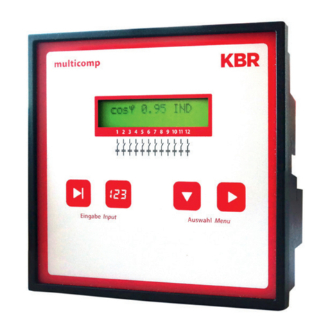
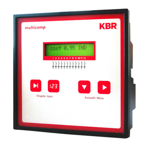
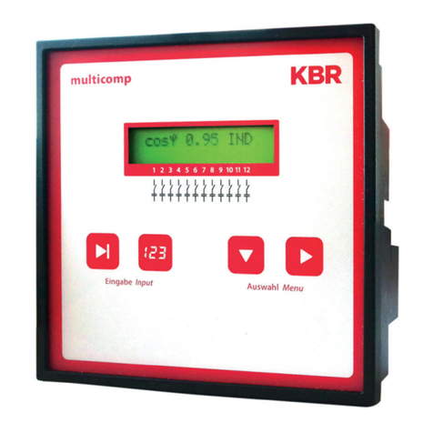
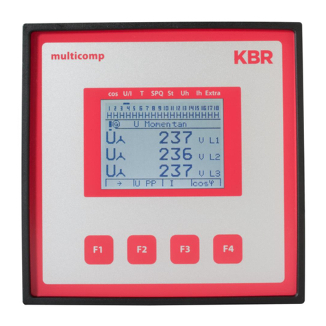
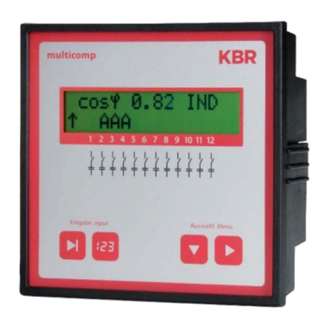
KBR multicomp D6 Series Instruction manual

24449_EDEKZA0031-2619-1_DE-EN
Information
Connection and start-up
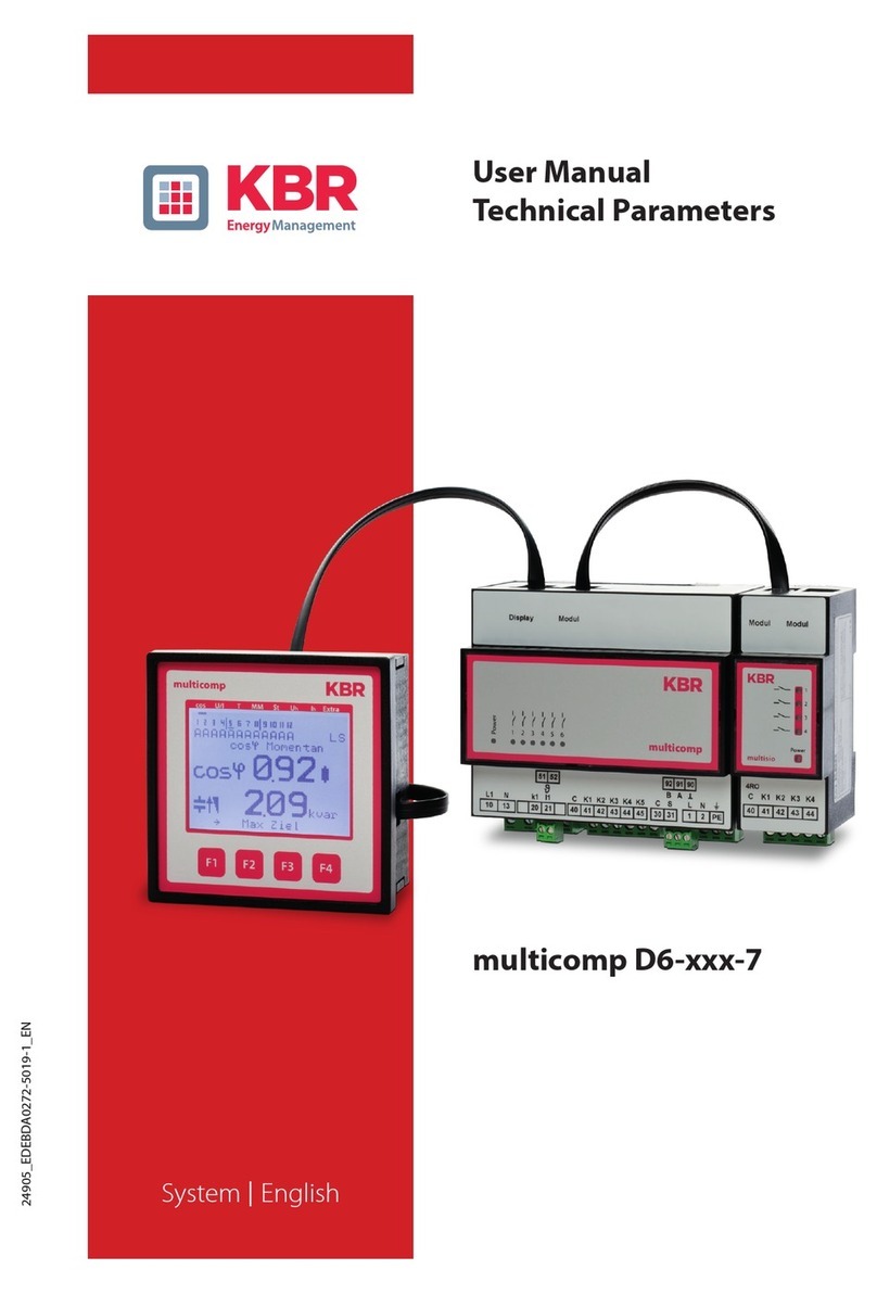
multicomp D6-xxx-7
System IEnglish

V7.00
24449_EDEKZA0031-2619-1_DE-EN
2
1 Introduction
Thank you for choosing this KBR quality product.
To familiarize yourself with device operation and conguration, we recommend you read
this manual carefully. This will enable you to make use of the entire range of functions
that this high-quality product oers.
The individual chapters serve to explain the technical details of the device and show how
to properly install and start up the device to prevent damage.
1.1 Instruction
This Instruction must be accessible to the user at all times (e.g. in the switchgear cabinet).
Even if the device is resold to third parties, the manual remains an inherent part of the
device.
Although the utmost of care has been taken in putting together this user manual, errors
may still occur. We would be very grateful if you could notify us of any errors or unclear
descriptions you may notice.
Disclaimer
The contents of these operating instructions have been carefully reviewed in terms of
the hardware and software described. Nonetheless, deviations cannot be ruled out, and
the manufacturer cannot guarantee 100% conformity. The specications made in these
operating instructions are reviewed on a regular basis; any corrections required will be
included in the next revision.

V7.00
24449_EDEKZA0031-2619-1_DE-EN
3
1.2 Explanation of safety relevant symbols
These operating instructions contain notes that must be observed for your personal
safety and to avoid damage to equipment. These notes are identied by a warning sign or
information symbol, depending on the degree of hazard they represent.
DANGEROUS VOLTAGE
„Warning“ means that death, major injuries or damage may occur if suitable safety pre-
cautions are not taken.
CAUTION
„Caution“ means that minor injuries or damage may occur if suitable safety precautions
are not taken.
NOTE
„Note“ is an important piece of information on the product, its operation or the respecti-
ve part of the operating instructions to which special reference is being made.
1.3 Safety notes
In order to prevent operating errors, device operation is kept as simple as possible.
This will enable you to start your device up quickly.
In your own interest, however, the following safety notes should be read carefully.
The applicable DIN / VDE regulations must be observed for installation!
Power supply connection, setup and operation of the device must be performed by
qualied personnel only. Qualied personnel as dened in the safety notes in this user
manual are those authorized to set up, ground and mark devices, systems and circuits
in accordance with applicable standards and regulations.
To prevent re and electric shocks, the device must not be exposed to rain
or humidity!

V7.00
24449_EDEKZA0031-2619-1_DE-EN
4
Before connecting the device to the power supply, check whether the local power supply
conditions comply with the specications on the device nameplate.
CAUTION
A faulty connection can lead to the destruction of the device!
For device connection, the data given in the connection chart must be complied with
(see„Connection chart“) and there must be no voltage in the connection lines. When
wiring, always ensure that all wiring material used is neither damaged nor defective and
that the polarity is correct!
In order to ensure proper and safe product operation, it must be transported, stored, ins-
talled and assembled in accordance with the specications, as well as carefully operated
and maintained.
A visibly damaged device must generally be considered unt for use and disconnected
from the power supply!
Error detection, repair and maintenance work may only be carried out in our facilities or
after contacting our service team. Opening the device unauthorized shall render your
warranty null and void. Correct operation can no longer be guaranteed!
Opening the device may expose live parts. Capacitors in the device may still be under
load, even if the device has been disconnected from all voltage sources. Open devices
must not be operated!
Systems that are at risk from lightning strikes must feature lightning protection for all
input and output lines!
1.4 Product liability
You have purchased a high-quality product. Only components of the highest quality and
maximum reliability are used.
Each device is subject to long-term testing before it is delivered.
For details on product liability, please refer to our general terms and conditions for elect-
ronic equipment, which you can nd at www.kbr.de.
Warranty device properties apply only if the device has been operated in accordance
with its intended use!

V7.00
24449_EDEKZA0031-2619-1_DE-EN
5
1.5 Disposal
Defective, outdated or disused devices must be properly disposed of.
If required, we are happy to dispose of the devices for you.
1.6 Overvoltage and lightning protection
It is recommended to install overvoltage protection measures to protect our high-quality
devices from damage. We also recommend to protect control voltage inputs and pulse
lines, if required.
2 Connection of the multicomp D6-xxx-7
2.1 Installation and assembly
The applicable DIN / VDE regulations must be observed for installation!
Before the device is connected to the power supply, check whether the local power
supply conditions comply with the specications on the nameplate.
A faulty connection can lead to the destruction of the device! A dierent power fre-
quency inuences the measurement accordingly.
The device must be connected in accordance with the connection chart.
Systems that are at risk from lightning strikes must feature lightning protection for all
input and output lines!
CAUTION
The control voltage as well as the applied measuring voltage of the device must be
protected by means of a back-up fuse.
When connecting the current transformer, the energy ow direction and the correct
assignment to the voltage path must be observed!
During installation, please also observe our notes on safety measures against overvoltage
and lightning in the chapter„Protective measures“ of this manual.

V7.00
24449_EDEKZA0031-2619-1_DE-EN
6
NOTE
The following points must be observed when connecting the device:
- Energy ow direction
- Assignment of measuring voltage input/current transformer input
Energy ow direction: When mounting the transformer, observe the current ow or
energy ow direction. If the current transformer is mounted the wrong way round, the
measured current will be negative.
Prerequisite is that energy is consumed.
Assignment - measuring voltage input / current transformer input:
The current transformer on terminal 20/21 (k1/l1) must be arranged in the phase where
the measuring voltage for terminal 10 (L1) is measured.
- The device will display positive current when connection and energy ow direction
are correct.
- If connected incorrectly, the current displayed is negative. Interchange the connec-
tions until the display shows correct values.
CAUTION
Before any interchanging, the current transformer must be shorted out!

V7.00
24449_EDEKZA0031-2619-1_DE-EN
7
F2
F1
+
52
Stromflußrichtung / current direction
L3
N
L2
L1
F3 F4
10
L1
13
N
-
51
21
l1
20
k1
41
K1
40
C
42
K2
2
N
43
K3
1
L
B
92
A
9091
K4 K5
44 45 3130
temperature probe
Temperaturfühler /
Relais /
Relay
C S
Module
Modul/
Display
OUT OUT
Stufen / Stages
multicomp D6-ESBSDS-1V1C6RO-7
zu weiteren Busteilnehmern
bzw. Leitungsabschluss /
to other bus devices
and line termination
max. C2 automat - max. C2 Automat
max. 1 A slow-blow - max. 1 A träge
max. C2 automat - max. C2 Automat
max. 1 A slow-blow - max. 1 A träge
circuit breaker - Trennvorrichtung circuit breaker - Trennvorrichtung
PE
*For supply voltage, see type plate
* Versorgungsspannung siehe Typenschild
*
Netz / power
Messspannung / measuring voltage
Hauptstrom / main current
CAUTION
The coil voltage for the capacitor contactors and the measuring voltage must be drawn
from the same phase, as only the measuring voltage is monitored (to protect the contac-
tors from direct reset in case of short-term single-phase power failure).
2.2 Connection diagram

V7.00
24449_EDEKZA0031-2619-1_DE-EN
8
Terminal:
1 (L) and 2 (N): Power supply connection
A control voltage is required to supply the device with power.
The unit is equipped with a multi-range power supply and may
be supplied by voltages of 100 – 240V ± 10% DC 50/60 Hz (see
nameplate for device voltage).
10 (L1,Lx):
13 (N,Ly):
Voltage measuring input
Input voltage both as PH-N and PH-PH measurement.
Direct measurement for 100... 500...600V AC. The measuring ran-
ge is congurable. Exceeding the measuring interval results
in an error message.
For higher voltages, connection via voltage transformers is
necessary (medium voltage measurement x/100 V), measuring
range from 500V to 30.0 KV Ph-Ph.
20 (k1) and 21 (l1): Measuring input for current
The measuring input for current must be connected via a current
transformer x/1A AC or x/5A AC.
When connecting the transformer, pay attention to the energy
ow direction and to the correct assignment of measuring volta-
ge input to current transformer.
30 (C) and 31 (S): Floating relay contact
This contact serves as a message or alarm output. During
operation, an audible or visual message may be activated or a
consumer switched o. The contact is open as long as the device
is dead as well as when there is an active message. Maximum
switching capacity 2A at 250V AC.
40 (C): Connection for voltage supply to the relay output terminals
41 to 45
The relays for the control outputs share the same connection to
the supply voltage.
2.3 Terminal assignment

V7.00
24449_EDEKZA0031-2619-1_DE-EN
9
Terminal:
41 (K1) to 45 (K5): Non-oating relay contacts
These contacts are used as control outputs for the capacitor
switching contactors. As long as the device is dead and for
stages that are not hooked up, the contacts are open. Maximum
switching capacity 2A at 250V AC.
51 (-) and 52 (+): Temperature sensor input
A temperature sensor, e.g. PT1000, can be connected to this
input to measure the switchgear cabinet temperature.
Temperature measuring range of – 20°C to 100°C +/- 2°C.
90 (earth):
91 (A)
92 (B)
Interface connection
For communication on the eBus or Modbus
3 Start-up guidelines for the multicomp D6-xxx-7
This guideline helps you to correctly start up the compensation controller multicomp
D6-xxx-7. It provides you with step-by-step instructions to help you nd the options
relevant for you in the operating instructions.
To begin with, there are two cases in which the start-up procedure for the
multicomp D6-xxx-7 diers.
Case 1: You have bought a complete compensation system from KBR, and the controller
is already installed. If this is the case, certain settings are already precongured in the
controller.
Case 2: You only bought the controller, or the controller with additional modules
(multisio D2-1T2RO, multisio D2-4RO, multisio D2-4CI and multimess D4) and individual
capacitor stages, but the system is not assembled. In this case, the controller is delivered
with the default settings (refer to chapter Default settings) and has thus not been precon-
gured.

V7.00
24449_EDEKZA0031-2619-1_DE-EN
10
3.1 Controller not precongured
If an uncongured controller is to be started up, the following procedure has to be per-
formed step by step.
1. Conguring additional modules
(multisio D2-1T2RO, multisio D2-4RO, multisio D2-4CI and multimess 14)
If there are no additional temperature, relay or induced current measuring modules, this
step can be skipped. To congure additional modules, connect them and the supplied
bus line to the basic module. The additional modules can then be activated individually
using a scan mode, which has to be triggered via the basic module‘s operating panel
and the DIP switches or scan buttons on the additional module. If the compensation unit
consists of several cabinets, the correct cabinet assignment has to be set up.
Detailed instructions for this step are given in chapter Settings under Modules / Display
submenu.
2. Conguring current transformer values
For the compensation controller to function properly, all current transformer parameters
have to be set correctly. Primary and secondary current of the transformer have to be set.
These parameters can be read on the nameplate of the current transformer. In addition,
the phase assignment of the transformer has to be set correctly. In the controller, the
phase (L1, L2, L3) in which the current transformer is integrated has to be set.
You can nd more detailed information on this topic in chapter Start-up under Transfor-
mer settings submenu.
3. Setting target cosine:
You can ask your energy supply company for the target cosine, which should be set up
at this point. The target cosine is by default set to 0.95 inductive (see chapter Default
settings).
You can nd more detailed information on this topic in chapter Start-up under Target
cosine submenu.

V7.00
24449_EDEKZA0031-2619-1_DE-EN
11
4. Conguring the capacitor stages
There are two ways of conguring the capacitor stages. The stages can be congured
manually or using the auto conguration mode (a connected current measuring module
is required).
The most important setting to pay attention to is the stage power. The stage power can
be looked up on the nameplate of the stage or the circuit diagram and then programmed
manually. The auto conguration mode then automatically sets this value. However, it has
to be checked and conrmed after each time the auto conguration mode is applied.
Detailed instructions for the auto conguration mode are given in chapter Extra , Start-up
, Stages , Stage , Auto conguration mode.
After the stage power has been congured, you have to set the detuning factor. This
factor can be read on the circuit diagram cover sheet or the nameplate of the stage.
If the compensation unit consists of several cabinets, the cabinet assignment should be
adjusted accordingly.
Detailed instructions for this step are given in chapter Start-up under Stages submenu.
5. Function test
After all values have been programmed, a function test should be performed. To do so,
the controller has to be taken o the voltage supply for a few seconds.
After re-connecting it to the voltage supply, the controller has to start automatically. If
the cosφ voltage is read out in the cosφ act. menu immediately after switching it on, the
value for cosφ should be low and inductive. After approx.
180 seconds, the controller starts to switch on the individual capacitor stages.
The cosφ, which can be read out in the cosφ act. Menu, should have risen compared to
previous values, or it should rise when switching on additional stages. If the compensati-
on unit is dimensioned correctly, the controller should compensate the set target cosine
after a certain period of time.

V7.00
24449_EDEKZA0031-2619-1_DE-EN
12
3.2 Controller not congured
If a controller already integrated into a KBR compensation unit by default should be used,
only the parameters of the current transformer have to be congured.
1. Conguring current transformer values
For the compensation controller to function properly, all current transformer parameters
have to be set correctly. Primary and secondary current of the transformer have to be set.
These parameters can be read on the nameplate of the current transformer. In addition,
the phase allocation of the transformer has to be set correctly. In the controller, the phase
(L1, L2, L3) in which the current transformer is integrated has to be set.
You can nd more detailed information on this topic in chapter Start-up under
Transformer settings submenu.
2. Function test
After all values have been programmed, a function test should be performed.
To do so, the controller has to be taken o the voltage supply for a few seconds.
After re-connecting it to the voltage supply, the controller has to start automatically. If
the cosφ voltage is read out in the cosφ act. menu immediately after switching it on, the
value for cosφ should be low and inductive. After approx.
180 seconds, the controller starts to switch on the individual capacitor stages.
The cosφ, which can be read out in the cosφ act. menu, should have risen compared to
previous values, or it should rise when switching on additional stages. If the compensati-
on unit is dimensioned correctly, the controller should compensate the set target cosine
after a certain period of time.
Am Kiefernschlag 7
D-91126 Schwabach
T +49 (0) 9122 6373 - 0
F +49 (0) 9122 6373- 83
E info @ kbr.de
www.kbr.de
KBR Kompensationsanlagenbau GmbH
This manual suits for next models
1
Table of contents
Other KBR Controllers manuals

KBR
KBR multicomp F144-MS-1V1C1TI6RO6DO-3 User manual

KBR
KBR F144-3PH User manual

KBR
KBR multicomp F144-MS-1V1C1TI6DO6RO-3 Service manual

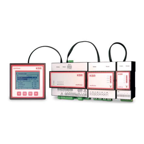
KBR
KBR multimax D6-5 Series User manual
KBR
KBR F144-MS-1V1C6-12DO-3 User manual
KBR
KBR multimax 3D6 User manual

KBR
KBR Multicomp 2F144-NC-1V1C06RO Operating instructions

KBR
KBR multicomp F144-MS-1V1C1TI6RO-3 User manual

KBR
KBR multicomp F144-NC-1V1C6DO6RO-2 Use and care manual
KBR
KBR F144-3PH User manual