MOUNTING DIMENSION FOR THE USE AS SIDE MOUNT FILTER
WIRING
CONNECTION
FUSE PROTECTION
USING THE QUICK GUIDE
• Provides information on handling, assembly and installation.
• Remains for later use at the product.
• Does not replace the electronically provided instructions for use.
This manual is intended exclusively for persons who are familiar with the logistics and installation. The person must have the
following qualications:
• Knowledge and understanding of the safety instructions.
• Skills for installation and assembly.
• Knowledge of EMC-conform wiring.
• Detection of hazards and risks of the electrical drive technology.
• Knowledge of IEC 60364-5-54.
• Knowledge of national safety regulations.
SAFETY INSTRUCTIONS
DANGER Interventions by unauthorized personnel !
Danger to life through electric shock and malfunctions !
► Modication or repair is only permitted by KEB authorized personnel.
NOTICE Getting more documentation
Hazards and risks through ignorance.
► Open the KEB homepage at www.keb.de.
► By entering the material number in the search eld, you will get the corresponding parts of the
instructions for use.
►Read the instructions for use carefully !
►Observe the safety and warning instructions !
TRANSPORT
The transport must be carried out by instructed persons, observing the following instructions.
CAUTION Maximum design edges and high weight !
Contusions and bruises!
►Never stand under suspended loads.
►Wear safety shoes.
►Secure devices accordingly when using lifting gear.
NOTICE Behaviour in case of transport damage
►When receiving goods, check the device for transport damage such as deformations or loose parts.
►In case of damage, contact the carrier immediately.
►Do not operate the device in case of transport damage!
STORAGE
Do not store the devices
• in the environment of aggressive and/or conductive liquids or gases.
• at places with direct sunlight.
• outside the specied environmental conditions.
UNPACKING AND CHECKING
• Make sure that no components are bent and/or isolation distances are changed.
• The device must not be put into operation in case of mechanical defects. There is no compliance with applicable safety
standards any more.
INSTALLATION
• If available, use the lifting eyebolts provided for installation.
• Do not stand under suspended equipment during installation.
• Mount the product according to the required degree of protection.
• Make sure that no small parts fall into the device during assembly and wiring (drilling chips, screws etc.). This also applies to
mechanical components, which can lose small parts during operation.
• The devices are intended for the use in a pollution degree 2 environment.
• Maximum ambient temperature 45°C
• UL / CSA: Ensure UL-compliant connection of all power connections according to the requirements given in the data
sheet.
The fuse values of the lters correspond to the fuse values of the corresponding drive controllers.
• Cable cross-sections and fuses must be dimensioned according to the design of the machine manufacturer. Specied
minimum / maximum values may not be fallen below /exceeded.
USE ON THE DRIVE CONTROLLER
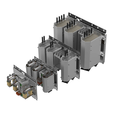
The mechanical housing sizes of the COMBILNE E6 back mount lters correspond to those of the COMBIVERT F6 drive
controllers.
COMBILINE E6 COMBIVERT F6
Housing
2 (14E6T60-1050, 16E6T60-1050) 2
3 (18E6T60-1050, 20E6T60-1050) 3
4 (22E6T60-1050) 4
START-UP AND OPERATION
WARNING Triggering of overcurrent protection devices
Risk of re or electric shock!
►Triggering of an overcurrent protection device will be a hint for an overload or short circuit. Triggering
a RCD may be caused by a leakage current.
► In order to reduce the risk of re or electric shock, live parts and other components of the device
should be checked and replaced in case of damage.
CAUTION High temperatures on the device
Burning of the skin !
►Cover hot surfaces so that they are safe to touch.
►If necessary, attach warning signs to the system.
►Check surface before touching.
►Let the device cool down before any work is carried out.
MAINTENANCE
The following maintenance work has to be carried out when required, but at least once a year by authorized and trained
personnel.
►Clean the product from dirt and dust deposits.
►In case of malfunction, unusual noises or smells inform a person in charge!
►In case of failure, please contact the machine manufacturer.
INSTALLATION / ELECTRICAL CONNECTION
DANGER Voltage at the terminals and the device !
Danger to life by electric shock !
►Never work under voltage on the device or touch exposed parts.
► For any work on the unit switch o the supply voltage and secure it against switching on.
►Wait until the drive has stopped in order that no regenerative energy can be generated.
►Never bridge upstream protective devices (also not for test purposes).
►Connect the protective earth conductor properly.
►Install all required covers and protective devices for operation.
For a trouble-free and safe operation, please pay attention to the following note:
► Check for reliable t of the device connections in order to avoid contact resistance and sparking.
DISPOSAL
► For professional disposal, follow the instructions in the instructions for use
Minimum distances Dimension Dimension in mm Distance in inches
A 0 0
B100 4
C 30 1.2
D 0 0
E 0 0
F 1) – –
1) Distance to front operating elements in the control cabinet
door.
The mounting dimension of the drive controller apply when used as back mount lter.
Mains connection 3-phase (L1, L2, L3)
L1
L2
L3
L1
L2
L3
PE
➀ ➁ ➂ ➃ ➄
L1 L1‘ L1
L2 L2‘ L2
L3 L3‘ L3
1: Mains fuse 3: Mains choke 5: Drive controller
2: Mains contactor 4: E6 lter
Part No. Connection
Cross-sectional area
Cross-sec-
tion Tightening torque
in mm² / AWG
L1, L2, L3 PE Output L1, L2, L3 PE Output L1, L2, L3 PE Output
14E6T60-1050
Spring-
loaded
terminal
Spring-
loaded
terminal Strand
Betatherm
0.2...6 / 24...10 6 / 10
−
−
−
16E6T60-1050 0.75...25 / 18...4 10 / 8
18E6T60-1050 4...35 / 14...2 16 / 6
20E6T60-1050 4...35 / 14...2 35 / 2
22E6T60-1050
M6 bolt for
crimp
connector
10...50 /
8...1/0 −50 /
1/0
10 /
88
Fuse protection for IEC
Part No. Input voltage
Max. fuse size
Class gG
SCCR 30 kA
14E6T60-1050
400 V
25A
16E6T60-1050 50A
18E6T60-1050 80A
20E6T60-1050 100A
22E6T60-1050 160A
Fuse protection for UL
Part No. Input voltage
Max. fuse size
Class RK5 Class gG
SCCR SCCR 30 kA Type
5 kA 10 kA
14E6T60-1050
480 V
25A −25A SIBA 50 140 06.25
16E6T60-1050 50A −50A SIBA 50 140 06.50
18E6T60-1050 60A −
63A
SIBA 20 189 20.63
COOPER BUSMANN
170M1365
60A LITTELFUSE
L70QS060
20E6T60-1050 − 90 A
100A
SIBA 20 189 20.100
COOPER BUSMANN
170M1367
90 A LITTELFUSE
L70QS090
22E6T60-1050 −125A 125A
SIBA 20 189 20.125
COOPER BUSMANN
170M1368
A
B
D
E
F
C
D


