Keith KICD User manual

KICD - Container Drive
INSTALLATION MANUAL
Original Instructions
©2020KEITHManufacturingCo.AllRightsReserved.KEITH,KEITHlogoandWALKINGFLOORareregisteredtrademarksofKEITH
ManufacturingCo.EquipmentmanufacturedbyKEITHManufacturingCo.isprotectedbynumerouspatentsbothdomesticandforeign.
DOC06452 Rev. A
Released: 2017-08-30
KEITH Manufacturing Co.
www.KeithWalkingFloor.com
World Headquarters
Toll-Free: 800-547-6161
Phone: +1-541-475-3802
Europe Headquarters
Phone: +31-342-422007
10777601

i DOC06452 Rev. A
INSTALLATION MANUAL KICD - Container Drive
Table of Contents
Contact Information - KEITH Manufacturing Co. ii
1.0 Introduction 1
2.0 Container Preparations 2
2.1 Container Alignment 2
2.2 Bracing 2
2.3 Hydraulic Tubing Locations 3
2.4 Cross-Members 3
2.5 Shimming 4
2.6 Bae Plate 6
3.0 Sub-Deck 7
3.1 Square Tubing 7
4.0 Drive Unit 10
4.1 Side Seal Support 11
4.2 Painting 12
4.3 T-Block 12
4.4 Hydraulic Tubing 13
5.0 Flooring 14
5.1 Slide Bearings 14
5.2 Floor Slats 16
5.3 Side Seal Options 20
5.4 Front Shield 22
6.0 Miscellaneous 22
6.1 Caution Decals 22
6.2 Front Guard 22
Appendix 1 - Tools 23
Appendix 2 - Materials 24
Appendix 3 - Check List 25
Appendix 4 - Bolt Torque Requirements 26

ii DOC06452 Rev. A
INSTALLATION MANUAL KICD - Container Drive
Contact Information - KEITH Manufacturing Co.
World Headquarters - USA
401 NW Adler St.
P.O. Box 1
Madras, OR 97741
Toll-Free: 800-547-6161
Phone: +1-541-475-3802
Email: Sales@KeithWalkingFloor.com
Europe Headquarters
Barneveld, The Netherlands
Phone: +31-342-422007
Email: EuroSales@KeithWalkingFloor.com
Canada
Brantford, ON
Phone: +1-519-756-9178
Email: CanadaSales@KeithWalkingFloor.com
México
Guadalajara, Jal.
Phone: +52-333-616-5079
Email: KMC_Mexico@KeithWalkingFloor.com
Australia
Waverley Gardens, VIC
Phone: +61-3-9562-2190
Email: AUSales@KeithWalkingFloor.com

1 DOC06452 Rev. A
INSTALLATION MANUAL KICD - Container Drive
1.0 Introduction
This manual explains procedures for installing the KEITH®KICD - Container Drive unloading
system. Many variables aect the installation, but the general process remains constant. Details
of the installation vary according to container features, slat selections, and installer preferences.
Optional sets of instructions are given for some operations to allow for exibility.
This manual focuses on the installation of a 150 mm [6 in] stroke system with SAE ooring.
Installation time varies and is between 35 hours and 100 hours, depending upon the experience of
the installer and the adaptability of the container. One person with welding skills can complete the
entire installation.
An ecient installation requires appropriate tools and accessible materials. A list of tools is found
in Appendix 1. Appendix 2 lists materials. The KEITH®KICD - Container Drive owner’s manual
contains more detailed information about the system and operation procedures.
WARNING: Installing the WALKING FLOOR®system will require some alterations to your
container.
Direct any questions to KEITH Manufacturing Co. or one of our international oces listed in this
manual.
IMPORTANT: When you perform welding on the system, the part on which welding is performed
must be directly connected to earth (properly grounded.)

2 DOC06452 Rev. A
INSTALLATION MANUAL KICD - Container Drive
2.0 Container Preparations
The container requires preparation before the system is installed. Planning ahead for the WALKING
FLOOR® installation requirements saves signicant preparation time,
2.1 Container Alignment
Check the compatibility of the drive unit with the container before making any alterations to the
container.
1. Adjust the container to meet these conditions:
A. The container must be straight to allow for proper parallel movement of the slats.
Determine straightness by sighting down a oor slat positioned in the container.
B. The cross-members on which the sub-deck mounts must be level, because the friction
based principle of the WALKING FLOOR® system requires a at oor. If there are
deviations exceeding 3 mm [1/8 in], make corrections.
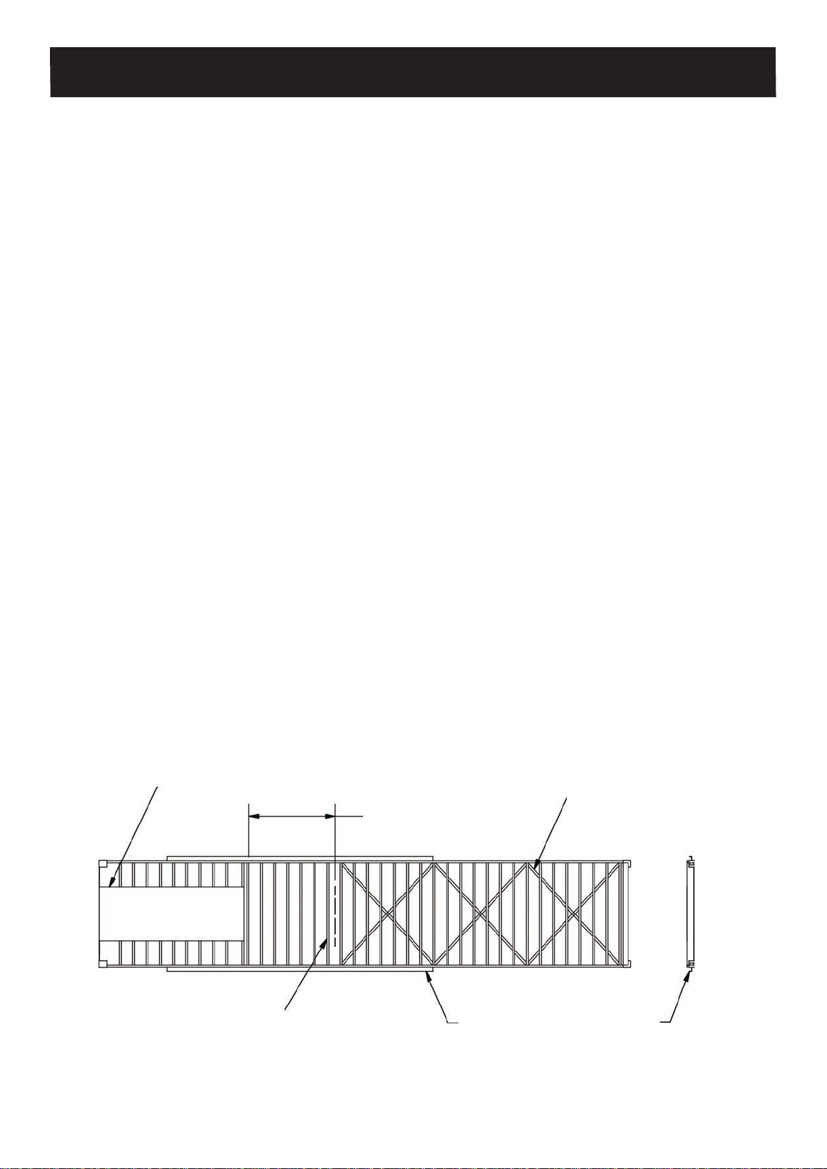
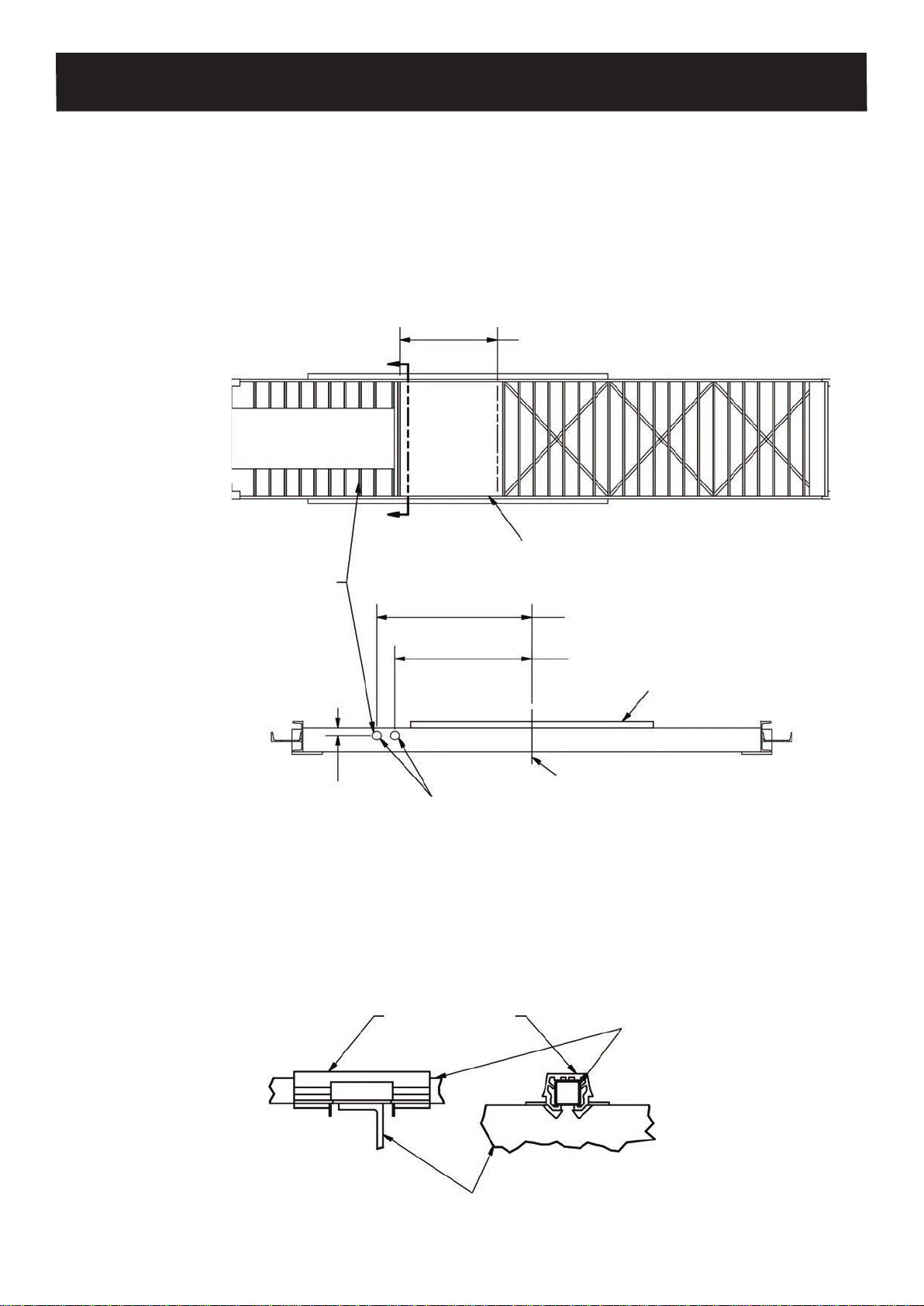
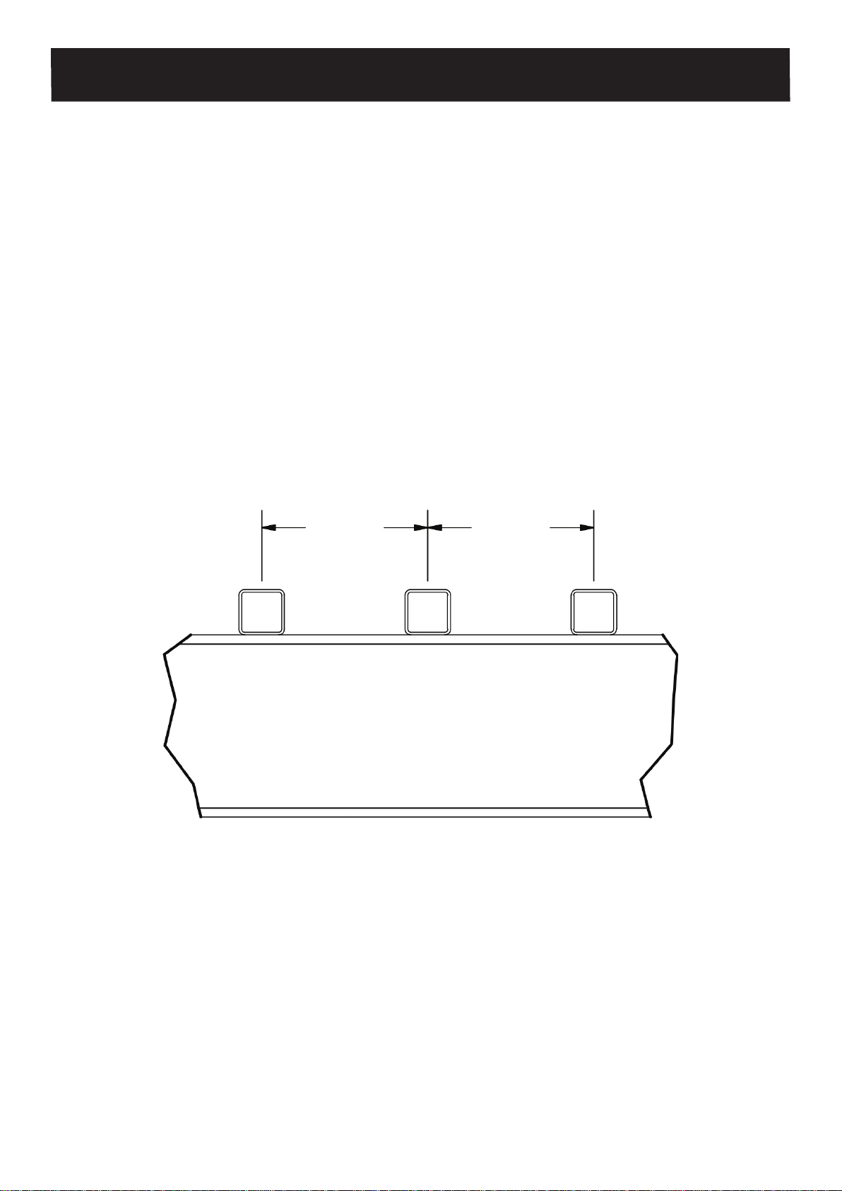
2.2 Bracing
Container bracing prevents warping.
1. Install bracing as shown in Figure 1.
• It is best to add bracing before removing the old oor because the oor keeps the container
straight. If at bar is used, make a cross-bracing because it will buckle easily under
compression. The bracing reaches to the drive opening. Weld or bolt the braces to each
intersecting cross-member.
2. Weld temporary bracing onto the outside of the side rails to keep the drive opening straight. This
is very important if the top of the container was cut out rst. Remove after completion.
3. Remove old ooring.
1980 mm [78 in]
Minimum Opening
6 mm x 50 mm
[1/4 in x 2 in]
Cross-Bracing
No bracing at
drive unit opening Temporary bracing welded to
outside of container rails to
keep drive opening straight.
Remove after completion.
5th Wheel Tunnel
Figure 1

3 DOC06452 Rev. A
INSTALLATION MANUAL KICD - Container Drive
2.3 Hydraulic Tubing Locations
Hydraulic pressure, generated by the tractor’s wet kit, powers the drive unit. Tubing must connect
the drive unit to the tractor.
The location of the hydraulic tubing cut holes are shown so that the tubing will line up with the drive
plumbing. Section 4.4 provides more information on this subject. A central location is preferable for
the quick-couplers in front of the container. This keeps hose lengths down, if they stay connected
while driving.
2.4 Cross-Members
Cross-members function as support for the sub-deck.
After removing the ooring, the cross-members need to be shimmed. See section 2.5.
1980 mm [78 in]
Minimum Opening
Holes for tubing cut thru
cross-members this side of
container, from drive opening
to front of container.
697 mm [27-7/16 in]
789 mm [31-1/16 in]
Remove cross-members to
make Drive Unit opening.
SECTION A-A
Centerline
35 mm [1-3/8 in]
38 mm [1-1/2 in]
Figure 2
#3-3003 Bearing 25 mm x 25 mm [1 in x 1 in]
Tubing
Figure 3
Shim Attached to Container Cross-Member

4 DOC06452 Rev. A
INSTALLATION MANUAL KICD - Container Drive
Remove cross-members to create an adequate opening for the drive unit (Figure 4). See Chapter 4
for more information about drive unit location.
Opening between channel at rear of tunnel to cross member.
Side view in container (Figure 4)
2.5 Shimming
1. The cross-members attached to the tunnel to the side rail need to be shimmed to the same height
as the tunnel 32 mm [1-1/4 in]. See Section B-B.
2. The WALKING FLOOR®system takes 150 mm [5-7/8 in] clearance from the bottom of cross-
members to the bottom of the sub-deck 25 mm x 25 mm [1 in x 1 in] tubing. The cross-members
need to be shimmed 35 mm [1-3/8 in] higher from the rear of the tunnel to the front of the rear
threshold. See Section C-C.
3. The tunnel area needs further shimming. Use 50 mm [2 in] wide at bar the full width of the
container. Starting at the front cross-member, place 8 mm [5/16 in] thick at bar on the rst 5
cross-members. On cross-members #6 and #7, place 6 mm [1/4 in] at bar. On cross-members
#8 and #9, place 5 mm [3/16 in] at bar. On cross-member #10, place 3 mm [1/8 in] at bar.
Clamp and weld in place. (Figure 6, Section D-D)
1980 mm [78 in]
Minimum Opening
Tunnel
Channel at
rear of tunnel Drive unit will be
welded to channel. Container
Cross-Members
Figure 4

5 DOC06452 Rev. A
INSTALLATION MANUAL KICD - Container Drive
Shim level to tunnel
at tunnel only. Shim 35 mm [1-3/8 in]
above cross-members
BB
Shimming the Cross-Members & Rear Bae Plate
C C
Shim to top of tunnel
at tunnel only.
Top of
Tunnel
32 mm [1-1/4 in]
SECTION B-B Dierent examples of Shimming
on top of Cross-Members
Minimum Gap 75 mm [3 in]
378 mm [14-7/8 in]
314 mm [12-3/8 in]
Shim 35 mm [1-3/8 in]
above cross-members
35 mm [1-3/8 in]
Bracing
Figure 5
SECTION C-C
Mount 3 mm [1/8 in]
bae plate on top of
existing rear threshold.
64 mm [2-1/2 in]
clearance for door
Existing rear
threshold
Shim level with rear threshold,
mount bae on top of shim.
150 mm [5-7/8 in]

6 DOC06452 Rev. A
INSTALLATION MANUAL KICD - Container Drive
2.6 Bae Plate
A bae plate extends forward from the door threshold to prevent material from sifting through the
oor when slats are in the forward position.
Starting 65 mm [2-1/2 in] from unload end of threshold, leaving clearance for the door, use 3 mm
[1/8 in] thick material to achieve the 150 mm [5-7/8 in] from the bottom of cross-members to top of
the bae plate. Come forward 315 mm [12-3/8 in] then down 100 mm [4 in] and weld 100%. Grind
welds at. See previous page, section C-C.
Figure 6 SECTION D-D
D D
Shim to go
wall to wall
Tunnel
8 mm [5/16 in]
Shim (x5) 6 mm [1/4 in] Shim 3 mm [1/8 in] Shim
35 mm [1-3/8 in]
Shim
5 mm [3/16 in] Shim

7 DOC06452 Rev. A
INSTALLATION MANUAL KICD - Container Drive
3.0 Sub-Deck
The sub-deck is the structure directly above the cross-members and underneath the oor slats. The
sub-deck consists of square steel tubing or U-shaped aluminum proles. The square tubing mounts
on top of the cross-members. Plastic oor bearings connect to the tubing.
3.1 Square Tubing
The proper installation of the square tubing is critical for maintaining drive alignment, oor
straightness and for optimal performance of the seal located between the oor slats. Raise the drive
unit into position. Do not weld at this time. The drive unit is in place for locating the end of 25 mm x
25 mm [1 in x 1 in] tubing.
1. Cut 25 mm x 25 mm [1 in x 1 in] tubes to proper length according to your container
measurements. The number of tubes installed equals the number of oor slats.
All sub-deck tubes must extend beyond cross-members by 50 mm [2 in], because bearings
require at least 50 mm [2 in] of tubing on both sides of a cross-member for proper attachment.
See details on the next page F, G & H.
2. Position and mount the tubes.
Tubing for SAE ooring is on 92.7 mm [3.65 in] centers (Figure 7).
Start at the rear of the container. Lay the two outside tubes in the container and separate them
with spacing jigs. Center the jigs so the tubes are the same distance from the side walls and then
weld in place. (See Figure 8)
Figure 7
92.7 mm
[3.65 in]
92.7 mm
[3.65 in]

8 DOC06452 Rev. A
INSTALLATION MANUAL KICD - Container Drive
E
E
E
F
D
25 mm x 25 mm [1 in x 1 in]
Tubing
Do not cover bae plate
with 25 mm x 25 mm
[1 in x 1 in] tubing
25 mm x 25 mm [1 in x 1 in]
Tubing
50 mm [2 in]
50 mm [2 in]
50 mm [2 in]
Lift drive unit in place for tube
location only at this time.
Do not Weld. 50 mm [2 in]
Do not weld 25 mm x 25 mm
[1 in x 1 in] tubing to drive unit
at this time.
Drive unit to be placed against
rear tunnel channel.
Figure 8
SECTION E-E
DETAIL D
DETAIL E
DETAIL F

9 DOC06452 Rev. A
INSTALLATION MANUAL KICD - Container Drive
Lay out the remaining tubes across the width of the container, spacing them with jigs. Keeping the
jigs above the cross-members, clamp the jig and tubes to every other cross-member. Be sure all
tubes attain the minimum overhang of 50 mm [2 in]. Remember to plan for the formed cross sill
attached to the drive unit. Plan the overhang into the drive gap according to the drive unit being
installed (Previous page, Figure 8).
Weld or huck bolt the square tubes to the shim that is attached to the cross members between jigs.
Move the jigs and make a connection at each intersection of a tube and a cross-member. Welds
should be 3 mm [1/8 in] llet, 20 mm to 30 mm [3/4 in to 1-1/8 in] long, and centered on the ange.
Excessive welding and too little cooling will cause cross-members to warp. Figure 10 suggests a
welding pattern. Starting each pass on the same side of the container gives sucient cooling time.
Figure 9
Figure 10
25 mm x 25 mm
[1 in x 1 in] Tube
X= Weld First Pass
O= Weld Second Pass
Container Cross Sils (Typ)

10 DOC06452 Rev. A
INSTALLATION MANUAL KICD - Container Drive
4.0 Drive Unit
NOTE: A minimum drive opening of 1980 mm [78 in] is necessary to maneuver the drive unit. (See
Page 4, Figure 4)
IMPORTANT: Do not damage piston rods. Do not lift drive unit by any of the hydraulic components.
Align and level drive unit.
Drive unit is butted against channel at rear of fth-wheel tunnel. (See detail E) Center the drive unit
in the drive gap. The 25 mm x 25 mm [1 in x 1 in] tubing should extend 50 mm [2 in] past the formed
cross sills at each end of the drive unit. The cross-drive should be parallel to container cross-
members.
Side to Side Alignment
Recommended method:
After the sub-deck is welded or bolted down, (to container, not drive unit) use a straight edge to
align the drive shoes with respective 25 mm x 25 mm [1 in x 1 in] tubing. Do this with at least two
shoes on each side of the container (Figure 11).
Optional method if container is perfectly straight:
Align the drive unit’s “centerline” marks with the container’s centerline.
Figure 11
Center drive shoes with 25 mm x 25 mm
[1 in x 1 in] tubing side to side.
Raise drive shoe up to
straight edge and level.
Drive unit welded to channel at rear of 5th wheel tunnel.
Straight edge
Bearing Bearing
Drive shoe

11 DOC06452 Rev. A
INSTALLATION MANUAL KICD - Container Drive
Height
Raise drive frame cross-member to the same height of shimmed cross-member.
This method gives the proper drive height as bearings are 6 mm [1/4 in] above the 25 mm x 25 mm
[1 in x 1 in] tube and the drive shoes connect directly to the oor slats. See Detail F.
Weld the drive unit in place.
Use 25 mm x 25 mm [1 in x 1 in] jig to weld 25 mm x 25 mm [1 in x 1 in] tubing to drive unit formed
channels.
4.1 Side Seal Support
Side seal options are discussed in Section 5.3. Some of the options require support from the sub-
deck.
1. Select a side seal option from Section 5.3.
2. Install support for the selected side seal option if necessary.
Plan the support so the top of the side seal will be level with the rest of the ooring.
Pieces of tube or angle can be attached on the cross-members to support the side seal.
Side seal shim
both sides
Shim has to be
required height.
NOTE:
Shim material to
go over drive area
both sides.
41 mm [1-5/8 in] is closest shim can be
to 25 mm x 25 mm [1 in x 1 in] tubing.
41 mm [1-5/8 in]
8 mm [5/16 in]
Figure 12
2337 mm [92 in]
G
DETAIL G

12 DOC06452 Rev. A
INSTALLATION MANUAL KICD - Container Drive
4.2 Painting
The factory paints drive units with red oxide primer.
1. Conrm that the drive unit is coated well with primer.
2. Treat the drive unit and sub-deck with a nishing paint.
IMPORTANT: Make sure that the following parts are protected when painting: cylinder chrome rods,
switching valve chrome rod, serial plate and any decals.
4.3 T-Block
Plastic T-Blocks provide a sliding surface and prevent material from going underneath the end of the
slats at the discharge end of the ooring. (Figure 13)
1. Align the T-Blocks with installed tubing. Keep the blocks 12 mm [1/2 in] away from the doors.
2. Drill and countersink bolt holes through the T-Blocks and bae plates.
3. Fasten T-Blocks to the bae plate. Self-tapping screws may be necessary if access is poor.
Countersink holes 6 mm [1/4 in] below the block top. Make sure the bolts (at-head socket caps)
are 4 mm [3/16 in] below the surface of the block.
Door
Center T-Block with
25 mm x 25 mm [1 in x 1 in] tubing
T-Block mounting bolts to be
mounted 4 mm [3/16 in] below
ush with top of T-Blocks 12 mm [1/2 in]
Door
Rear threshold
Minimum 12 mm [1/2 in] gap
between door & T-Block
T-Block
SECTION G-G
G
G
Figure 13

13 DOC06452 Rev. A
INSTALLATION MANUAL KICD - Container Drive
4.4 Hydraulic Tubing
Section 2.3 discusses the location of hydraulic tubing.
IMPORTANT: All components and tubing must be kept absolutely clean to prevent dirt from entering
the system.
1. Determine tube locations and lengths.
2. Cut tubes to length.
3. Position tubes.
Use the weld on tube clamps supplied with the kit or use rubber grommets or PVC tubes to
protect the tubing when installing tubes through cross-members
4. Connect tubes to drive unit.
Connect the pressure line to outside line that is connected to the switching valve port labeled
“PUMP” and return line to inside line that is connected to the switching valve port labeled “RES”.
5. Mount quick couplers just inside front of container.
Connect the male coupler on the pressure line (outside line to switching valve port stamped
“pump”). Connect the female coupler to the return line (inside line to switching valve port stamped
“res”) (Figure 14). Apply hydraulic sealant.
Figure 14
Return Line
Female
Coupler
Pressure Line
Male Coupler Weld on
tube clamps
After drive unit is welded in
place attach hydraulic oil lines.
SECTION H-H
HH
Front of Container

14 DOC06452 Rev. A
INSTALLATION MANUAL KICD - Container Drive
5.0 Flooring
After paint dries, the ooring can be installed. The slats slide on plastic bearings. The aluminum
oor slats are bolted to shoes on the cross drives.
5.1 Slide Bearings
1. Compare bearing dimensions with shim on the cross-member ange width. The gap in the
bearing should exceed the ange width of the shim of the cross-member. The standard bearing
gap is 62 mm [2-7/16 in]. Milling can enlarge the gap to 100 mm [4 in].
2. Snap 6 bearings (3003 Long) 100 mm [4 in] opening on the sub-deck over the load end of
cylinders. (See Detail J of Figure 15)
3. Snap one row of 3003 bearings on the sub-deck over the load end of drive frame. Snap 1830
mm [72 in] splash bearing over sub-deck in front of them. Snap another row of 3003 bearings in
front of them. Take 12 of the 1830 mm [72 in] splash bearings and cut them in half to 915 mm [36
in] to make a total of 24 splash bearings and snap them on the sub-deck in front of them. Snap on
another row of 3003 bearings in front of them. (See Detail I of Figure 15)
4. Snap bearings on the square tube at the junction of each cross-member. No tools are needed.
These 6 Bearings have a
100 mm [4 in] cut out to
t over stiener at bar.
Hydraulic cylinders
in center of drive.
Cross-Drives
Figure 15
DETAIL J

15 DOC06452 Rev. A
INSTALLATION MANUAL KICD - Container Drive
IMPORTANT: Do not put a bearing on the front cross-member of the container if the oor slat will
slide beyond the center of this bearing in the backward position.
Figure 15
I
J
Install one row of 3003 Bearings,
cut o ears on bottom to t.
Install one row of 915 mm [36 in] splash
bearings.
Cut (12) 1830 mm [72 in] in half to make
(24) 915 mm [36 in] splash bearings.
Drive Unit
Install one row of 3003 Bearings,
cut o ears on bottom to t.
Install one row of 1830 mm
[72 in] Splash Bearings.
Install one row of
3003 Bearings.
DETAIL I
Front of Container

16 DOC06452 Rev. A
INSTALLATION MANUAL KICD - Container Drive
5.2 Floor Slats
1. Determine length of oor slats.
The slats have to reach from 50 mm [2 in] from the doors to a minimum of 300 mm [12 in] from
the closest point on the front wall at oor level. This implies that the maximum length of the slats
is 350 mm [13-3/4 in] shorter than the inner length of the container. For example, maximum slat
length for a 150 mm [6 in] stroke unit in a 12.04 M [39 ft 6 in] container is 11.69 M [38 ft 4 in].
WARNING: Make sure that the slats do not bump the front wall.
2. Determine drilled oor bolt hole location.
Make sure the cylinders are all the way to the rear of the container when determining the oor bolt
hole location.
The ooring is to be predrilled before installation. Measure the distance from 50 mm inside the
door to the rst set of holes in the drive shoes. Use this distance to set the shoe drill jig at the rst
hole.
(Note: If multiple containers are being outtted, it is benecial to place the drive units at the same
distance from the rear of the container. Then all of the ooring will be drilled in the same location.)
(See Figure 16)

17 DOC06452 Rev. A
INSTALLATION MANUAL KICD - Container Drive
Figure 16
Door
Floor Slat
50 mm [2 in]
50 mm [2 in]
Door
End of slat to rst
hole in drive shoe.
End of slat to rst
hole in drive shoe.
Drive Shoe SECTION I-I
II
Table of contents
Other Keith Automobile Accessories manuals
Popular Automobile Accessories manuals by other brands

KIDDY
KIDDY EVO-LUNA I-SIZE Directions for use

Tuff Tonneaus
Tuff Tonneaus 524 FITTING INSTRUCTION

Curt Group
Curt Group 13387 installation instructions

Rear view safety
Rear view safety RVS-2CAM Product manual installation & instructions

Westfalia
Westfalia 304 204 300 113 Installation and operating instructions

Toyota
Toyota PZ408-E2555-00 installation instructions