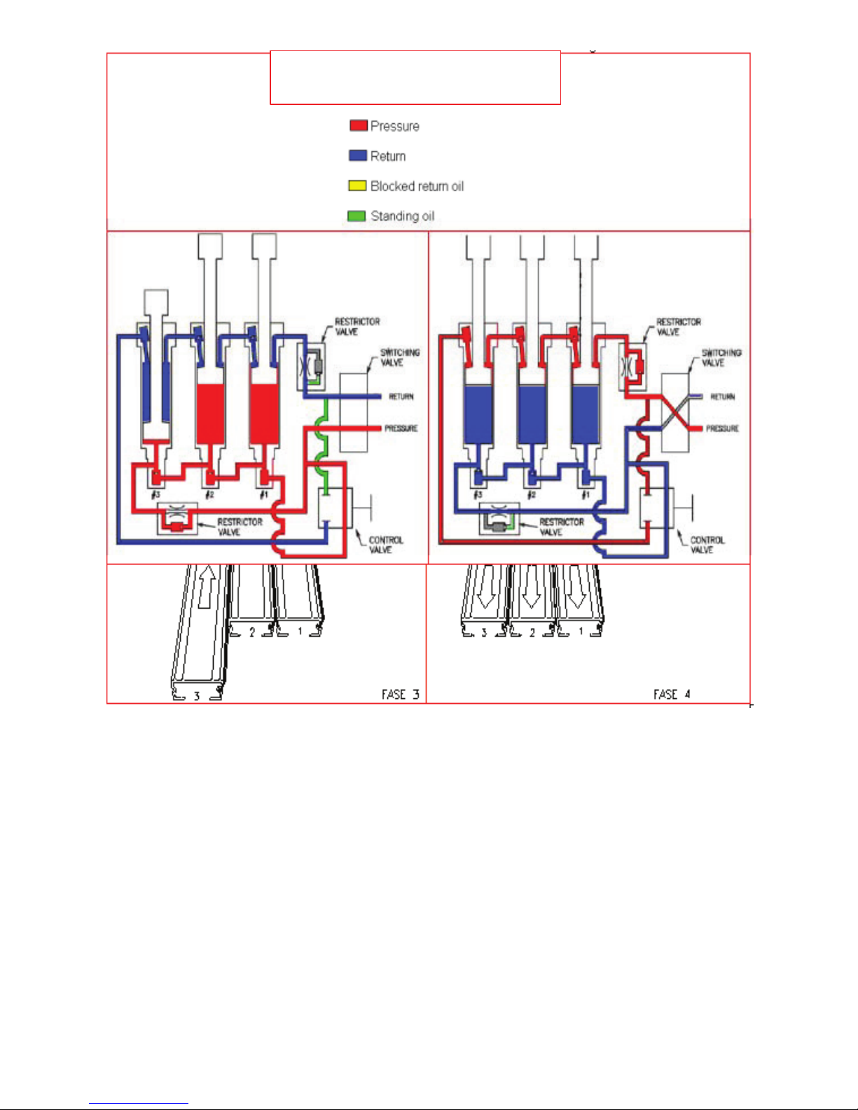
Keith WALKING FLOOR Workhorse User manual

OWNER’S MANUAL
Version: English, 002, June 2008
Updated 7/12/17

1
Table of Contents
1 Introduction ...............................................................................................................................
.
2 Description of the WALKING FLOOR®system ......................................................................
2.1 Use of the WALKING FLOOR system ..............................................................................
2.2 Operation of the WALKING FLOOR system ....................................................................
3 Technical specications of the WALKING FLOOR Workhorse ..............................................
3.1 Specications of the hydraulic installation ........................................................................
4 Operation ...............................................................................................................................
4.1 Manual operation ..............................................................................................................
4.2 Electric operation ..............................................................................................................
4.2.1 Electrical control Load / Unload / On / O.......................................................................
4.2.2 Electrical control On / O.................................................................................................
5 Components.............................................................................................................................
5.1 The cylinder........................................................................................................................
5.2 The check valve..................................................................................................................
5.3 The switching valve............................................................................................................
5.4 The on/o valve..................................................................................................................
5.5 The control valve................................................................................................................
5.6 The hydraulic plumbing......................................................................................................
5.7 Installation of oor slat with Kwik-Klamp®system ............................................................
6 WALKING FLOOR Workhorse system maintenance................................................................
7 Solving problems......................................................................................................................
7.1 Emergency Provision.........................................................................................................
8 Warranty...................................................................................................................................
8.1 Warranty conditions .................................................................................................................
Registration card......................................................................................................................
2
3
3
3
7
7
9
10
11
13
14
15
15
16
16
16
17
17
18
19
20
22
23
24
25

2
Introduction
We at KEITH Mfg. Co. and KEITH WALKING FLOOR Europe, thank you for having chosen the
KEITH®WALKING FLOOR®loading and unloading system. We are proud of the fact that we
manufacture the simplest and most trouble-free loading and unloading system. With the KEITH
WALKING FLOOR system you have the versatility of a at oor, combined with the opportunity to
load and unload practically any material you desire.
The following pages contain a description of the operation and the maintenance of your KEITH
WALKING FLOOR system, a troubleshooting manual and working drawings of a number of the most
important components of the system. Important information is also provided concerning the hydraulic
installation on your vehicle. You must ensure that this hydraulic installation satises the stated
requirements. We maintain a website at www.keithwalkingoor.com which provides an up to date
information resource from which manuals can be downloaded.
Make sure that you have read and understood the manual completely before you use the KEITH
WALKING FLOOR system. If you have problems or require advice do not hesitate to contact us. It
goes without saying that we will be pleased to help you!
Once again, thank you for choosing a KEITH WALKING FLOOR loading and unloading system.
Yours Faithfully,
All information in this document is oered in good faith and is believed to be reliable. The right to change or amend is
hereby expressly reserved. The user is not discharged of ascertaining himself on the correctness of the information.
KEITH WALKING FLOOR Europe is not responsible for any misinterpretation or errors.
© 2008, KEITH Mfg. Co. All rights reserved. KEITH. KEITH logo, WALKING FLOOR are registered trademarks of KEITH Mfg. Co. Equipment manufactured by
KEITH Mfg. Co. is protected by numerous patents both domestic and foreign. WALKING FLOOR® is a product and brand of KEITH Mfg. Co.
Keith Foster
Founder
KEITH Mfg. Co.
Mark Foster
President
KEITH Mfg. Co.

3
2. Description of the WALKING FLOOR®system
WARNING:
The large forces exerted by the oor when moving can result in damage to equipment
which may result in serious injury or death. Always ensure that this manual has been
read and fully understood by the operator. We advise that the operator keeps this
manual with the vehicle at all times. Always ensure that ‘best practice’ is employed
when using our systems. If in any doubt do NOT use this equipment and seek further
assistance from your company’s safety ocer.
2.1 Use of the WALKING FLOOR system
The system is built up from a number of separate components. These components are
assembled in such a way that they are only suitable for the conveying purpose described in the sales
contract. Should you wish to convey other materials then please contact the supplier of your trailer.
2.2 Operation of the WALKING FLOOR system
The KEITH®WALKING FLOOR system can be used for loading and unloading most materials.
Moving the load with the system is based on the friction between the load and the oor. The oor
consists of a number of oor slats placed side-by-side (the width of the oor determines the precise
number of slats required).
1 X-DRIVE (3) 3 ON / OFF VALVE 5 SWITCHING VALVE
2 MOUNTING BLOCK 4 LOAD / UNLOAD BLOCK 6 CYLINDER (3)
Three double-acting hydraulic cylinders move the oor slats in a cycle with four phases. The forces exerted by
the cylinders are transferred to the slats by three cross drives. Each cross drive moves 1/3 of the total number
of oor slats.
The oor slats slide over plastic sliding bearings that support both the upper part and the sides of the slat.
Dierent oor slats, varying in width, surface area and material, have been developed to provide optimum
operation with various types of load. The unloading cycle is composed of the following four phases, the loading
cycle is the opposite. (Figure1.2a and 1.2b).
Figure 1.1: KEITH WALKING FLOOR Workhorse drive-unit

4
Cylinder 1 (and slats #1) moves towards the front of the bunker. Because only
1/3 of the oor is moving, whereas 2/3 of the oor is not, the load will not move
(the friction of this major oor area exceeds the friction force caused by the
Walking Floor slats). At the end of its stroke, the cylinder actuates a check valve
that allows the oil ow to start phase 2:
Cylinder 2 (and slats #2) moves towards the front of the bunker; again the load
will not move. At the end of its stroke, the cylinder actuates a second check valve
that allows the oil ow to start phase 3:
KEITHWalkingFloor Workhorse
Oil flow diagram
Fi
g
ure 1.2a
Phase 1:
Phase 2:
®
®

5
Cylinder 3 (and slats #3) moves towards the front of the bunker; again the load re-
mains still. At the end of the stroke, when all cylinders are lined up, an actuator at-
tached to the cross drive mechanically switches the switching valve. The switching
valve switches the pressure from the front end to the rear end of all cylinders, this
starts phase 4:
Cylinder 1,2 and 3 (and all slats) move back towards the open side of the bunker.
Because of the friction force between the oor and the load, the load will move over
a distance equal to the stroke of the hydraulic cylinders. At the end of the stroke the
switching valve switches the pressure to the rear end of all cylinders. The cycle is now
completed and starts with phase 1 again.
KEITHWalkingFloor Workhorse
Oil flow diagram
Figure 1.2b
Phase 3:
Phase 4:
®®

6
The position of the two control valves (internal) determines the loading or the unloading cycle. A
manual or electrical load- / o- / unload valve operates these valves.
The (un)loading time is determined by the speed of action of the cylinders, which depends on oil
ow to the cylinders and the cylinder size. The force the cylinders transfer to the oor determines the
maximum load, which can be (un)loaded. The cylinder force is dependent on the oil pressure and the
cylinder size.
The pump determines both the ow and the maximum oil pressure, and therefore the (un)loading time
and the weight, which can be handled. To protect the system, the pressure relief valve, set at 210 bar,
limits the pressure.
NOTE:
.For faster (un)loading, the oil ow must be increased; pressure has no inuence on
(un)loading time.
.The system operating pressure is determined by the load resistance and not by the
pressure relief valve setting of the pump.
.Conveying products for which the system has not been designed can cause damage to
the system. We therefore advise you to contact your supplier about this rst.

7
3. Specications of the WALKING FLOOR Workhorse drive unit
Cylinders 3
standard ø 102 mm
stroke 200 mm.
Weight 477 kg.
Capacity ø 102 mm 26.300 kg. at 140 bar
Pump
max. 210 bar
max. 110 l/min.
3.1 Specications of the hydraulic installation
Always consult the supplier of your drive unit to ensure you choose the correct hydraulic power unit.
Figure 3.1 shows the components of the hydraulic installation in a hydraulic diagram.
1 Bleed 5 PTO 9 Return lter
2 Hydraulic reservoir 6 Return line from lter 10 Return / Pressure tubing 1”
3 Suction tubing, Min. 2” 7 Exhaust tubing, Min 3/4” 11 Quick coupling (M)
4 Pump 8 Pressure relief valve, 12 Quick coupling (F)
Max. 210 BAR
The hydraulic installation must meet the following requirements:
PUMP/ PTO: The quantity of oil that will be pumped in the system determines the loading and unload-
ing time; the oil pressure determines the maximum total weight that can be handled.
Figure 3.1 Hydraulic diagram
Volume – 150 liter
Max.
110 l/min
Return
Pressure

8
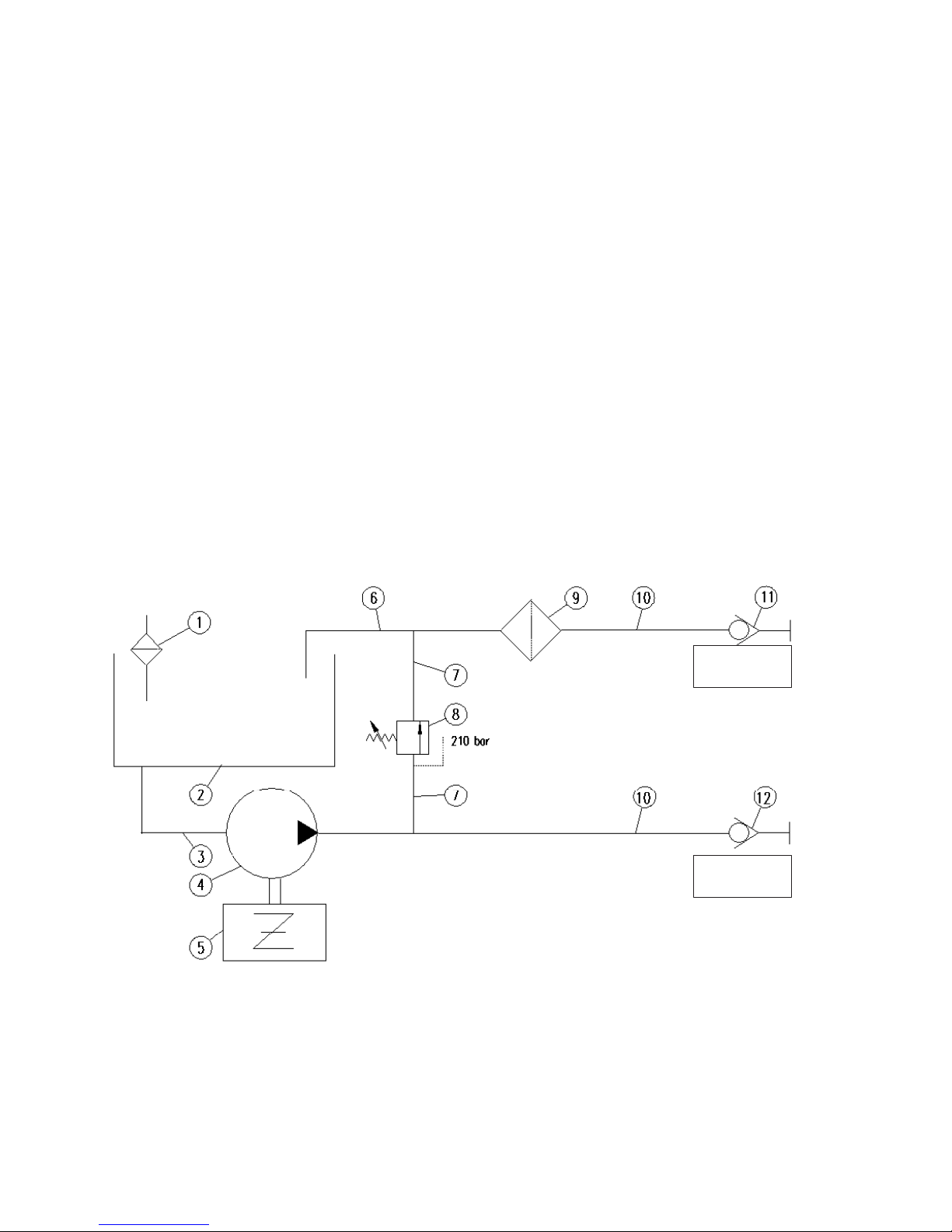
The KEITH®WALKING FLOOR® Workhorse System is designed for a recommended maximum oil ow of 110
l/minute. And a recommended maximum speed of 2.6 m/min.
A high power take-o (PTO) ratio (greater than 1:1) reduces the size of the pump for a given rotational speed.
This is generally the best alternative, technically as well as nancially. Compare the performance of the motors
in order to be certain that the motor can drive the pump. Also, check that the rotational speed of the motor will
not be greatly reduced by the load. Compare the maximum permitted loading of the PTO with that of the pump.
OIL:
The hydraulic oil must be of high quality, suitable for a pressure of 210 bar. The ISO viscosity must be 46
(for example Chevron AW 46 hydraulic oil), while in cold conditions a viscosity of 32 must be used.
Conditions of extreme cold demand hydraulic uids of aviation quality.
RESERVOIR:
The volume of oil in the reservoir must be equal to or greater than the oil ow per minute.
The reservoir must be lled to a level of 80-90%. Suction and return tubing must be placed so that cavitations
will be prevented. The ller cap must have a bleed capability.
PRESSURE RELIEF VALVE:
The hydraulic installation must have a pressure relief valve that is adjusted to 210 bar. Ensure that the
pressure relief valve is capable of sustaining the oil ow.
WARNING:The correct adjustment of the pressure relief valve is very important. If this is too low it is possible
that the system will not load or unload; if it is too high, the system may be damaged.
Measures to follow:
FILTER:
The lter in the return tubing must have a degree of ltration of 10 microns. In conditions of extreme cold it
is better to use ltration of 25 microns. Ensure that the nominal ow volume of the lter is the same as the
maximum oil ow that can occur in the system.
HYDRAULIC PLUMBING:
All hoses must be suitable for a pressure of at least 300 bar.
Suction Plumbing: in order to prevent cavitations, the oil ow to the suction inlet of the pump must be
unhindered. This requires suction tubing with a sucient diameter (at least 2” or 50 mm) that is as short as
possible (not more than 1.5 m), with out constrictions. Cavitations can also be caused by bends or elbows in
the pipe work – a straight line is best. Ensure that the hose cannot collapse with the suction.
Pressure plumbing: the hose from the tractor to the trailer must be 1” or 25 mm.
Return plumbing: the hose from the trailer to the lter must also be 1” (25 mm). The hose from the return lter
to the reservoir must be at least 1¼” (32 mm).
QUICK-COUPLINGS:
Tractor: Male on return (to the reservoir)
female on pressure (from the pump)
Trailer: female on return (from the “TANK” port on the lter block)
male on pressure (to the “PUMP” port on the lter block)

9
4. Operation
WARNING:
The large force exerted by the oor can result in damage to equipment and serious injury or death.
Always ensure that this manual has been read and understood by the operator. Take the following
precautionary measures:
• First open the doors before switching on the pump.
• Make sure that nobody is under the system when the pump is switched on.
• Ensure that during unloading no people or animals are in the immediate neighbourhood
of the location where the load can end up. We suggest that no one should be within 5 m
of the discharge danger zone.
• Ensure that there is always someone close to the emergency switch during
loading and unloading.
• Always switch o the pump during maintenance or service activities.
• Always switch o the pump when the vehicle is being driven and when the system is not
in use.
Two modes of operation are possible: manual and electrical; the person operating the system during
loading or unloading must be able to see the place where the load will be placed.
GENERAL TIPS:
• Depending on the type of load, a part of it can remain on the oor after the
unloading operation. This can be prevented by the use a Cleensweep tarp system,
a moving headboard or a piece of canvas, possibly attached to a moving head
board or attached to the front bulkhead with clips.
• In order to limit the eect of friction between the oor and the load, (so as to protect the
load or the oor) a piece of canvas can be laid over the whole oor and xed at the
front to the moving headboard. With a simple arrangement it is possible to roll it up
at the rear during unloading.
• The speed of the oor can be changed by changing the speed of the motor. Ensure that
the maximum permitted pumping rate is not exceeded.
• Ensure that the material can be freely unloaded: do not push against the material
stacked behind the oor.
• Take care that the load does not damage the front wall or headboard. The force exerted
by the moving load can be considerable!
• In frosty conditions, stop the three cylinders at the beginning of the unloading movement.
As soon as unloading starts, the oor slats will move together to the tail end of the
trailer and will detach the load from the side walls.

10
4.1 Manual operation
Starting the oor operation:
1. Open the trailer doors.
2. Attach the hydraulic quick couplings to one another.
3. Turn on the PTO and bring the engine to the desired number of revolutions (rpm).
Unloading / loading:
1. Select the desired operation to be performed by the system; unload / load.
2. Set the on/o handle in position; on. The oor will now begin to function.
Stopping:
1. Set the on/o handle in the position; o. The oor will now stop.
1. Switching valve
2. Manual Load/Unload valve
3. Manual On/O valve
Figure 4.1: Manual operation

11
4.2 Electric operation
Starting the oor operation:
1. Open the trailer doors.
2. Attach the hydraulic quick couplings to one another.
3. Turn on the PTO and bring the engine to the desired number of revolutions (rpm).
Unloading / loading:
1. Set the control push button for the system in the desired position; unload / load.
2. Set the on/o switch on the control box in the position; on
The oor will now begin to function.
Stopping:
1. Set the on/o switch on the control box in the position; o
1. Switching valve
4. Electric On/O valve
5. Electric Load/Unload valve
Figure 4.2: Electric operation

12
Emergency stop
The system with an optional KEITH®electrical control box is provided with an emergency stop push
button. If a dangerous situation arises during the operation of the oor it can be stopped immediately
with the emergency stop.
Manual operation in an emergency
In case of an interruption in the electrical power supply, the system can be switched on/ o manually.
Operate the handle on the block between the pressure and return connection.
Switching o
1. Stop the oor
2. Switch the PTO o and uncouple the quick couplings, if necessary.

13
4.2.1 Electrical control Load / Unload / On / O

14
4.2.2 Electrical control On / O
i l` hNUM=a bdo bbp
olq^qfkdCe^ka ib
probqv
_bi lt=ifa

15
5. Components
WARNING:
The large force and pressure caused by the hydraulic forces in the system can
cause serious injuries. Always switch o the pump during maintenance or
service work.
5.1 The cylinder
The three cylinders are the drive elements in the KEITH®WALKING FLOOR®system.
The cylinders are attached to the frame by a bolt construction. Each piston rod, or extension of the
piston rods, are attached to a cross drive with two clamps.
The above gure shows the dierence between the cylinder compilation.
For possible repair of a cylinder, in all cases a #2 cylinder will be supplied. Besides the replacement
for a #2 cylinder, this cylinder can be modied for the purpose of a cylinder #1 or #3. For
modication to cylinder 1, the plug, check valve and the spring at the end of the cylinder needs to be
removed. When a cylinder #3 is needed, the check valve, the spring and plug needs to be removed at
the front of the cylinder.
After replacement of a cylinder, followed by a full sequence of loading and/or unloading at full load:
Check the torque of the bolts with which the cylinder is attached to the frame - torque 170 Nm.
Check the torque of the bolts in the cylinder clamps - torque 170 Nm. Check the system for leaks.
Figure 5.1: The Cylinder

16
5.2 The check valve
The four check valves are the sensors of the KEITH®WALKING FLOOR®system. The check valve
detects when the cylinder has reached the end of its stroke and opens in order to allow the oil from
the following cylinder to ow to the reservoir. The check valves are located at the front and rear of
the cylinder in the heads on top of the cylinders. The valves are operated by the piston or piston rod
inside the cylinders.
5.3 The switching valve
The only function of the switching valve is to change the pressure from one side of the cylinders to
the other side. This ensures that the cylinders move in the opposite direction. The switching valve is
mechanically operated at the end of the stroke of cylinder No.1 and cylinder No. 3.
Figure 5.3: The switching valve
5.4 The On / O Valve
The valve, manually and/ or electrically operated, sets the oor in operation. In the <OFF> position
the oil ows via the valve directly back to the reservoir. The system will not operate if the pressure
and return plumbing is not correctly connected.
Manual Electric Figure 5.4: The On / O valve
1 Valve housing
2 Non-valve housing
3 Filter block
4 Filter
5 Maintenance Lever
6 Manual valve
7 Electric valve
1 Tail end cap
2 Valve Housing
3 Front end cap
4 Threaded rod

17
5.5 The control valve
This valve, which is manually operated, determines the direction of movement of the system.
The valve has two positions:
-Fully Withdrawn ; unloading
-Fully Depressed; loading.
Before the oor system is started the correct direction must be set.
5.6 The hydraulic plumbing
All hydraulic plumbing is internally completely hollow. A considerable part of the hydraulic circuit is
internal; the external plumbing for both manual and electrical operation are shown in respectively
gures 4.1 and 4.2. Ensure, when work is being carried out on the system, that all couplings, covers
and plugs make a good seal (“O” – ring or at seal).
1 Valve housing
2 Valve coil
3 Handle
Figure 5.5a: The Manual Control valve
2 Load end cap
3 Unload end cap
4 Control valve
Figure 5.5b: The Electric Control valve1 Pilot valve housing

18
5.7 Installation of the oor slat with Kwik-Klamp®System

19
6. WALKING FLOOR®Workhorse system maintenance
WARNING: The large force and pressure can cause serious injuries. Always switch o the pump
during maintenance or service work.
Two conditions that contribute to the life of the KEITH® WALKING FLOOR system are:
• Clean oil, free from contamination
• Correct torque for the bolts. The bolts of the cylinder clamps and of the oor proles
must be checked regularly.
The following maintenance must be carried out:
• after the system has been working for 6 hours;
• every half year or after every 150 operating hours whichever is sooner.
1. General inspection of the system and the oor.
Inspect the system for damage.
Check for oil leaks.
Check the system for smooth operation.
Check the temperature. No single part may be warmer than 60ºC (it must be possible to
touch all parts with the bare hand).
2. Change the oil lters:
a. Filter in the return plumbing of the hydraulic installation. Optional:
b. Filter in the pressure plumbing (FA 20ME MXW2-GDL20, 20 microns).
Unscrew the lter housing. Clean up any oil that has leaked. Fit a new lter.
3. Check the torque of the cylinder bolts.
a. Cylinder clamps: Torque: 170 Nm.
b. Bolts which connect the cylinder to the frame : 200 Nm
Table of contents
Other Keith Automobile Accessories manuals
Popular Automobile Accessories manuals by other brands

Road Ranger
Road Ranger ET 400011 Installation instruction

APE OFFROAD
APE OFFROAD BC-3400-WD05 Instructions for Installation and Care

Metra Electronics
Metra Electronics 99-7316 installation instructions

Whelen Engineering Company
Whelen Engineering Company Justice Competitor JE2NFPA installation guide

SuperATV
SuperATV IN-WS-K-TRX installation instructions

MeiTrack
MeiTrack MT90 user manual