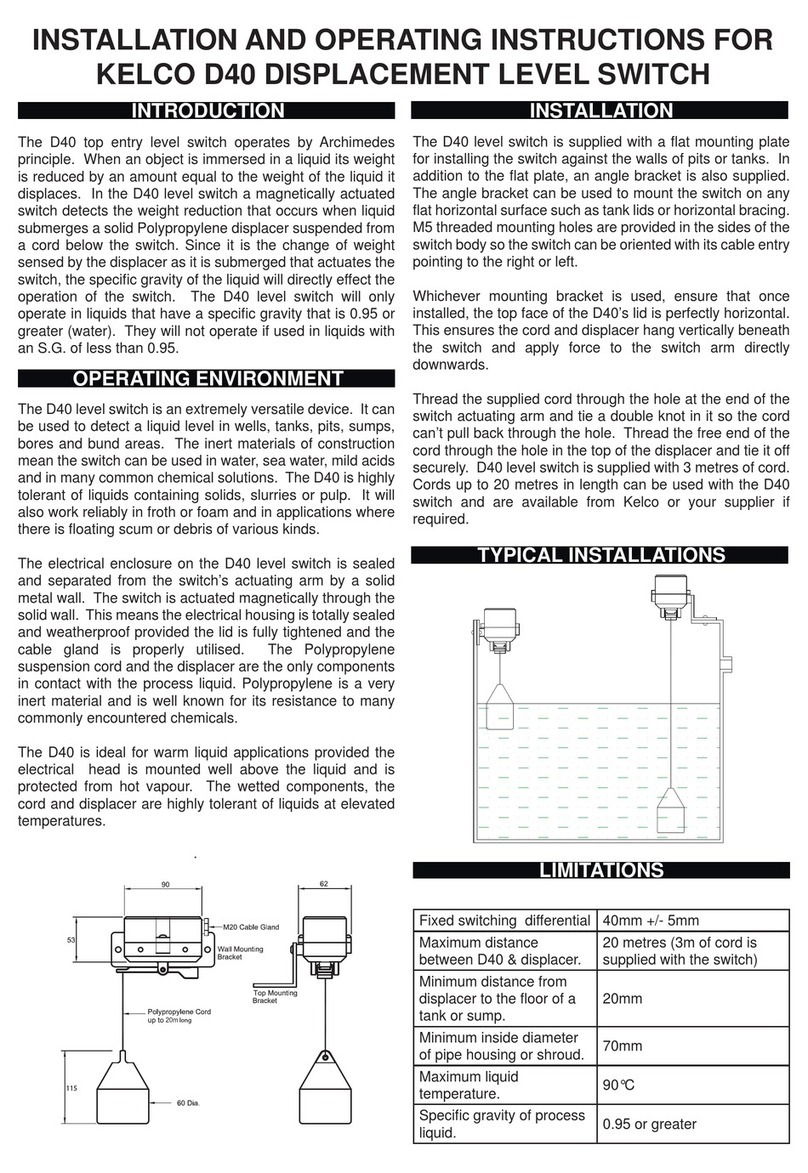
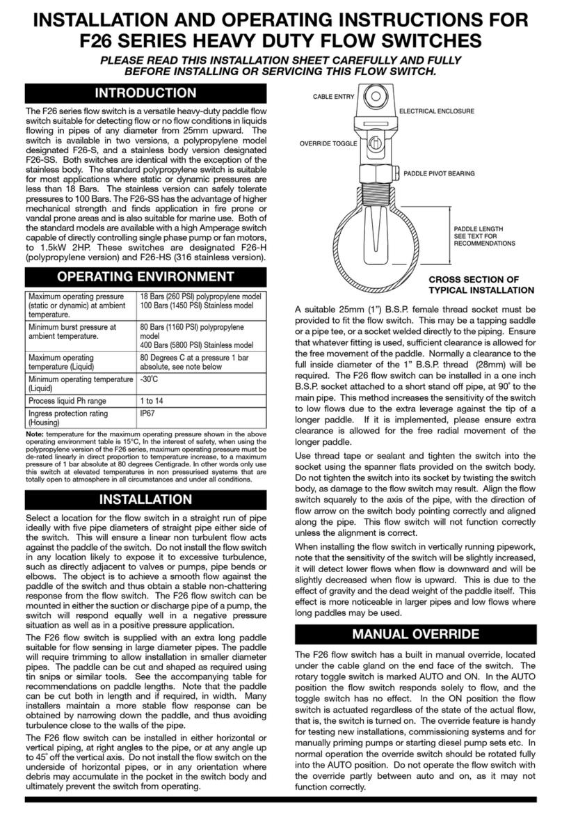
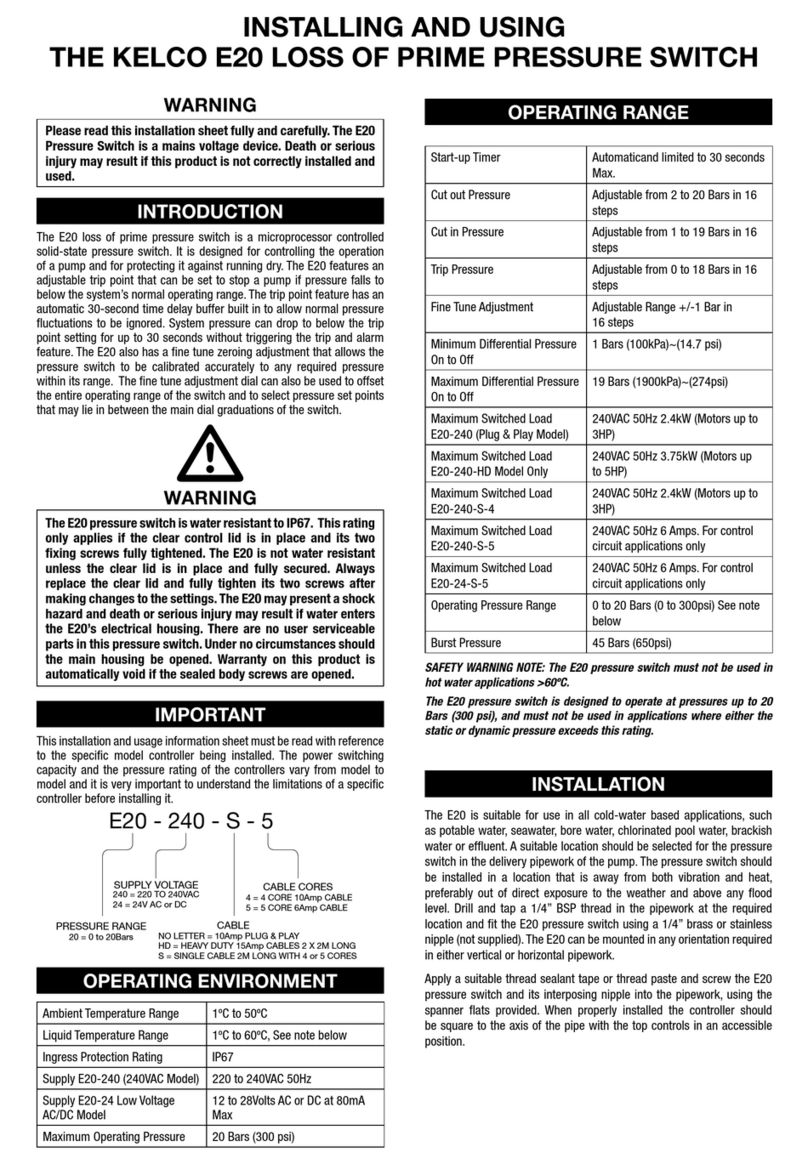
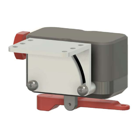
KELCO E30 Mk2 Assembly instructions

KELCO E30 Mk2
DIGITAL PRESSURE SWITCH
INSTALLATION & PROGRAMMING
MANUAL
KELCO Engineering Pty Ltd
Sydney Australia
www.kelco.com.au
Version 090119

2
VERY IMPORTANT SAFETY NOTICE
PLEASE READ THIS BEFORE INSTALLING THIS CONTROLLER
The E30 Mk2 is an industrial control device. It is specically designed for
use in industrial, agricultural and mining applications. It must never be
used for any application other than for the aforesaid purposes. The
installation, commissioning of this pump controller requires extensive
knowledge of pump engineering and electrical engineering. Installation
must always be carried out by a qualied pump engineer and all electrical
work associated with this controller must be carried out by a licensed
electrician. This industrial control device must not be operated by persons
(including children) with reduced physical or mental capabilities, or lack of
experience and knowledge, unless they have been given supervision or
instruction concerning the use of this pump controller by a person
responsible for their safety.

3
IMPORTANT: READ THIS FIRST
DO NOT EXPOSE THE E30 Mk2 TO VIBRATION. INSTALL ONLY IN
PIPEWORK THAT DOES NOT VIBRATE. Vibration will damage the
electronics within the E30 and will void your product warranty.
This E30 Mk2 digital pressure switch has been fully tested and calibrated.
It is set to use kPa in mode 1 and it has its start-up and run-on timers both
set to 5 seconds. It is set to close relay 1 at 100kPa and open it at 200
kPa. All other functions are turned o. On start up, the E30 will run a pump
connected to relay 1, using its start-up timer. If it nds pressure in the pipe
system it will continue to run the pump. If pressure is lost, the pump will
continue to run for 5 seconds, held on by the E30’s run-on timer. If pressure
fails to return, the pump will be shut down after the run-on period. Pressing
and releasing the (R) button on the E30 will repeat this basic process.
THE BUTTONS
The E30 Mk2 is controlled and congured using 4 onboard buttons.
(R) Reset button. Stops the pump(s) and restarts the E30 when released.
(˄) Up arrow button. For increasing program settings.
(˅) Down arrow button. For decreasing program settings.
(P) Programming button. For stepping through the menu and entering
settings into memory.
THE LIGHTS
The E30 Mk2 includes 3 multicolour lights to indicate activity.
Pump: This light is GREEN when a pump is running and RED when the
pump is stopped.
Timer: This light may be GREEN or RED when a timer or special function
is running.
Remote: This light is BLUE when remote input No. 1 is closed and o
when the remote is open. The light is RED when remote input No. 2 is
closed and o when the remote is open. This light is PURPLE when both
remote inputs 1 & 2 are closed.

4
LCD SCREEN BACKLIGHT
The LCD backlight can be turned on or o.
To turn the light o press and hold down the (˅) button. Press and release
the (R) button. Release the (˅) button. Repeat to turn the light on. The
light remembers the state it was last left in, if power is turned o. The light
can be left permanently on or o as required.
TEMPERATURE
The E30 monitors its internal temperature when running. Pressing the
(˅) button while the controller is operating normally displays the current
internal temperature.
PRESS (and release) THE (P) BUTTON
When the E30 is powered up, pressing the (P) button, holding it down
for 1 second and releasing it takes you to the top of the menu. Pressing
and releasing the (P) button loads whatever the screen is displaying into
the E30’s memory. The memory is non-volatile and settings are retained
when power is o. You can exit the menu at any time by pressing and
releasing the (R) button. Any settings you have made up to that point will
be retained. There is no need to step all the way through the menu when
making a change to a setting.
INSTALLING THE E30 Mk2
1) Do not install the E30 in a fully exposed outdoor location. The E30
isweatherproof,however,toensurealongreliablelife,werecommend
it be protected from direct exposure to the sun and rain. A skull cap
is provided with the E30 and we recommend it be used to protect the
E30 when direct observation of the LCD screen is not required.
2) Do not expose the E30 to freezing. If the pipework in which the
E30 is installed freezes, the pressure sensor in the E30 may fail. If the
E30istobeusedinareaswherelowtemperatureswillbeencountered,
always lag the pipework for several metres either side of the E30.
Also lag the base of the E30 to prevent the unit and any adjacent
pipework from freezing.
3) Do not use this controller in hot water applications. The E30 is not
designed to be used in water hotter than 60ºC.

5
4) Never expose the E30 to static or dynamic pressures greater than
20 Bars, 290 psi.
5) DonotinstalltheE30 in asectionofpipethat is subject tovibration.
Vibration will cause premature failure of the electronic components
within the controller.
6) Never install the E30 in the suction pipe of the pump or in any
location where it may be subject to partial vacuum conditions.
LOCATION
Install the E30 in a location that is sheltered from direct exposure to the weather.
The E30 is weatherproof and is supplied with a protective cover. However, to
ensure a long reliable life from the E30 we recommend it be protected from direct
exposure to the weather wherever possible. Intense sun light will eventually
cause degradation of the pressure switch’s enclosure and in extreme cases may
cause overheating of the electronics inside the E30. It is therefore advisable to
protect the E30 from the weather whenever possible.
The E30 can be wall mounted using the wall mounting bracket kit supplied with
each unit or it can be installed directly onto pipework. The location of the tapping
point is important. The E30 responds to positive pressures only. It should never
be installed in pipework that is subject to partial vacuum (negative pressures). Do
not install the E30 in the suction pipework of a pump. The tapping point should be
in a location that is away from valves, elbows and concentric reducers. The E30
can be installed in either horizontal or vertical pipework. Flow direction has no
impact on the performance of the pressure switch. Install the E30’s tapping point
in a section of pipe that typies the pipework in the general system. If water
hammer is a potential issue in the system’s pipework, wall mount the E30 and run
a length of small diameter capillary tube between the tapping point and the E30.
Coil the capillary tube so the tube acts as a snubber and absorbs the pressure
shock from the water hammer.
The E30 will read the line pressure at its tapping point. Consideration should be
given to the layout of the pipework and its eect on the reading accuracy. If the
system is subject to dynamic pressure, that is, pressure generated as a function
of uid movement within the pipe system, then the location of the tapping point
will eect the E30’s ability to read the pressure in a sensible manner. If the pipe
system is only subject to static pressure, that is, pressure that may uctuate but
is from essentially stationary liquid within the system, then the tapping point is
unimportant as pressure within such a closed system will be uniform at all points.

6
DYNAMIC PRESSURE
Consider the sections of pipe depicted in the sketch below. In sketch (A) the
pressure as read by the E30 when water ows will be less than the pressure read
by the pressure gauge. The dierence between the two readings will be directly
related to the ow velocity and the ratio of the two pipe diameters. The E30 will
see the pressure as lower than that seen by the pressure gauge. This is due to
the higher velocity through the small pipe and thus lower pressure than the
pressure in the larger pipe where the velocity is lower. In sketch (B) both the
pressure gauge and the E30 will read the same pressure since the velocity is
constant between the two tapping points. In sketch (C) the E30 will read the
dynamic pressure as higher than the pressure as read by the pressure gauge.
This is the reverse of the situation in sketch (A)
Note that in a static situation with no ow the pressure gauge and the E30 will
read the same pressure in all three pipe congurations.
Careful consideration should therefore be given to the location of the tapping
point. When water is owing the tapping points location will eect the pressure
reading and thus what the E30 actually displays.
A
B
C

7
INSTALLATION
The E30 consists of two separate parts, the process connection and the electrical
housing. The two parts are locked together by an Allen screw located under the
electrical housing. As supplied, the two parts are separate allowing the process
connector to be screwed onto pipework using a suitable 1/4” BSP pipe nipple (not
included). The provision of a separate process connector means the E30 can be
easily installed in awkward locations particularly when the tapping point is located
close to pipe bends or other obstructions. In eect, the process connection acts
as a union and can be screwed onto a pipe nipple and installed in the pipework.
The electrical housing can then be tted onto the process connection and locked
in place with the Allen screw.
To lock the two parts of the E30 together, with the electrical housing located on
the spigot and in position, press down with the at of your hand on the top face of
the lid of the electrical enclosure. While pressing down, screw the 4mm Allen
screw fully through the housing using the 3mm Allen Key (supplied). Tighten the
screw and then release your hand from the top of the housing. Pressing down
with your hand on the housing preloads the O-ring seal between the housing and
the process connection. It enables the M4 Allen screw to easily screw fully through
the side of the housing. Do not screw the Allen screw through the housing without
rst preloading the O-ring in the manner described above. To do so will result in
the Allen screw cutting a thread through the housing and reducing the designed
preload against the O-ring. This in turn will compromise the seal between the two
parts of the pressure switch.
M4 Allen head locking screw
Wall bracket
Locking Bolt
Process Connection 1/4" BSPF

8
Process connector screwed
onto a 1/4 BSP nipple in turn
screwed into a pipe tapping
point
Locking Screw
1/4 BSP Nipple
(Not included)
O-Ring seal must be in
place, clean and in
good order

9
E30 MOUNTED DIRECTLY ON A PIPE
ATTACHING THE ELECTRICAL HOUSING
Once the process connector has been installed, t the electrical housing
onto the spigot on top of the process connector. Take care that the sealing
O-ring on the top stem of the assembly is in location and in good order.
There is a at keying face on the cylindrical body of the process assembly
that keys the electrical housing onto the process assembly and aligns it
correctly. To secure the electrical housing onto the process adaptor an
Allen head cap screw is supplied.
With the electrical housing located on the spigot and in position, press
down with the at of your hand on the top face of the electrical enclosure.
While pressing down, screw the 4mm Allen screw fully through the housing
using the 3mm Allen Key (supplied). Tighten the screw and then release
your hand from the top of the housing.

10
WALL MOUNTING THE E30
The E30 pressure switch is supplied with a wall mounting bracket that can be
used to mount the pressure switch in locations away from the pressure tapping
point. To bracket mount the E30, rst install the bracket by drilling a hole pattern.
Secure the bracket to the wall or mounting using suitable screws (not supplied).
Fit a 1/4” BSP elbow (not supplied) to the E30’s process port using Teon tape.
The elbow should point squarely toward the cable glands on the E30. Install a
suitable tube adaptor into the elbow to facilitate connection to a length of capillary
tube. Typically, the capillary tube to use for this will be 6 to 8mm diameter.
Wire up the electrical head of the E30 and fully tighten all cable glands. Lock the
electrical head onto the wall bracket using the red bolt supplied with the E30.
Note that there are two ears on the wall bracket that engage in two notches on the
under side of the E30’s electrical housing. Using a suitable tube adaptor terminate
the capillary tube at the pipe system’s tapping point. If water hammer or violent
pressure surges are likely, coil the capillary tube between its two termination
points so the added length of the capillary tube acts as a shock absorber.
DETACHING THE ELECTRICAL HOUSING
WARNING: Always switch o the power and de-pressurise the pipe
system before attempting to remove the electrical housing.
To allow easy removal of the E30 from the pipework, the electrical housing
can be detached from the process adaptor. Removing the electrical
housing allows access to the process adaptor without the need to disconnect
wiring. To remove the electrical assembly undo and completely remove
the M4 Allen head locking screw. Once the locking screw is removed, lift
the electrical housing straight o, do not twist it when doing this. Once the
electrical housing has been removed, the process adaptor can be
unscrewed from the pipework. Simply reverse this procedure to ret the
electrical housing to the E30, taking care to ensure the O-ring on the top of
the process adaptor is in place and is clean and in good condition.

11
TYPICAL WALL MOUNTED E30 Mk2
The single locking bolt secures
the E30 to the wall Bracket
Screw a 1/4 BSP 90 Degree elbow (not supplied)
into the process port on the E30. The inlet port
on the elbow must be alligned downward to
accept a capillary tube adaptor and to
stand clear of the wall
VERY IMPORTANT SAFETY NOTE :-
A pressure relief valve should be tted to any system that can exceed the
pressure rating of any component on that system. Alternately, always
conrm that the pressure safety limits of individual items are compatible
and not compromised without the tting of appropriate safety devices, i.e.
a Pressure Relief Valve (PRV).

12
WALL BRACKET DRILL PATTERN
74 mm
60 MM
4 x 6mm
Holes
137 mm
148mm
126mm
3 X M20x1.5 CAble Glands
1/4" BSP Process connection
Female
Removable wall mounting
Bracket
Removable cap

13
ELECTRICAL INSTALLATION
All electrical work associated with the E30
must be carried out by qualied electrical
personnel and all electrical work must
conform to AS/NZ standards and to local
wiring rules.
INTRODUCTION
When used with its HD terminal link in place the E30 can directly control
single-phase motors to 2.4kW via its Relay 1. No interposing contactor is
required for such applications. The E30 can also be used to control 3 phase
motors of any size via an appropriate interposing contactor.
WARNING: The contactor control circuit must never exceed 240VAC.
NeverseriesconnecttheE30relaycontactsandcontactorcoildirectly
across 2 phases.
IMPORTANT
A means for disconnection of the E30 must be incorporated in the xed
wiring in accordance with the wiring rules.
The E30 requires a stable 220V to 240V AC supply when operated from
the mains. It can also be operated from an 18 to 24V AC or DC supply by
utilising the low voltage active terminal LV and neutral terminal N (see the
included wiring diagrams). When operated from a low voltage DC supply
the terminals LV and neutral N are not polarity sensitive. Pay attention to
cable sizes and ensure cables are adequate for the specic pump motor
load. This is particularly important where long cable runs are to be used in
the installation. If the voltage drop associated with the starting of the pump
WARNING

14
THE HD (Heavy Duty) TERMINAL
The E30 contains a solid-state switch (HD Heavy Duty drive) that can be
used to protect the contacts of Relay 1 by eliminating the destructive arcing
caused by the starting and stopping of motors. The solid-state switch is
accessible from the HD terminal on the terminal block. We recommend the
HD drive be used whenever the E30 is used to directly control a single
phase motor. The HD drive should not be used when the E30 is connected
to a contactor, external timer, low wattage relay or to any other external
device where voltage free contacts are required. It is strictly intended for
the direct control of highly inductive AC motor loads. The HD terminal and
the E30’s built in relays must never be directly connected to a DC motor
under any circumstances.
When the HD terminal is linked to the normally open terminal of Relay 1,
the HD drive in eect parallels a 42 Amp solid state switch across the
relay’s normally open contacts. This increases the momentary current
carrying capacity of the relay’s contacts to well over 60 Amps. The solid-
state HD drive is only activated for a brief period when the motor starts and
stops. It eectively handles the high inrush current associated with the
motor starting, and it provides a current path for the destructive back EMF
associated with the motor stopping. To use the HD drive, place a heavy
link wire between the HD terminal and the Normally Open terminal of
Relay one.
The HD terminal must be left unused or only ever linked to Relay
1 Normally Open. It must never be used for any other purpose
and it must never be connected to any external device. Under no
circumstances connect the HD terminal to the terminals of Relay
2. The HD terminal must be regarded as live at all times and at
full mains potential.
WARNING

15
BROWNOUT OR BLACKOUT
If a blackout or brownout occurs the E30 will not retain any memory of
where in its run or stop cycle it may have been, it will simply shut down the
pump. When power resumes, the E30 will reboot, and under acceptable
pressure conditions, restart the pump and run any timer settings from the
beginning. A manual reboot can be done at any time by pressing and
releasing the E30’s reset button.
CABLES
The E30 Mk2 has 3 X M20 cable glands. The cable glands can accept
cable from 7 to 9mm diameter. See sketch for assembling the cable gland
components. The controller is supplied with a set of steel crimp rings. The
crimp rings are to provide strain relief for the controller’s cables. To use the
crimps, place one on the cable approximately 3 to 4mm below the end of
the cable’s outer sheathing. Crimp the two ears of the ring at using bull
nosed pliers. Pull the cable back through the cable gland until the crimp
ring’s ears are fully located into the slots in the cable gland housing.
Rubber Plug
Backing Washer
M20 Gland Nut
Plug unused cable glands
using the rubber plugs
(supplied). Fully tighten
the gland nut to seal the
unused cable port.
Crimp the ears of the
strain relief ring onto the
cable and pull the cable
back into the slots in the
gland housing.
Cable 7mm to 9mm diameter
Controller Housing
Robber Grommet Backing Washer
4mm

16
VOLTAGE LIMITS ON TERMINALS A & N
Maximum Supply Voltage 260VAC
Minimum Supply Voltage 110VAC
SUPPLY VOLTAGE LIMITATIONS
VOLTAGE LIMITS ON TERMINALS LV & N
Maximum Supply Voltage 25VAC 50/60Hz or 25VDC
Minimum Supply Voltage 18VAC 50Hz or 18VDC
RELAYS
The E30 Mk2 houses 2 relays. Relay 1 has S.P.D.T contacts. Relay 2
has S.P.S.T normally open contacts. Relay 1 is normally regarded as the
pump control relay and relay 2 is normally regarded as the alarm relay.
When operating the E30 as a dual pump controller, relay 2 is used to
control the second pump.
With the HD terminal linked to the NO terminal of Relay 1, the E30
can directly control a single phase motor up to 2.4kW. Without the
HD terminal link in place, relays 1 & 2 are limited to directly
controlling a motor to 0.75kW. Both relays can control motors of
any size via interposing contactors.
CONTACT RATINGS FOR RELAYS 1 & 2
16A at 250VAC Resistive Load PF > 0.9
16A at 30VDC Resistive Load PF > 0.9
50mA at 5VDC Minimum Load
MAXIMUM PUMP MOTOR LOAD FOR RELAY 1
10A at 240VAC 2.4kW Inductive Motor Load
IMPORTANT: When directly controlling a pump motor through relay 1,
always link the HD terminal to relay 1 Normally Open terminal and make
sure the maximum switched motor current never exceeds 10 Amps. On a
pump motor P1 must not exceed 2.4kW.

17
The power required to drive the E60 depends on the supply, AC or DC and
on temperature. The table below gives the maximum power required from
various supplies at 25°C. As temperature increases the power requirement
will reduce. For example, at 30°C the power requirement will be
approximately 3% less than the values given in the table. The measurements
expressed in the table represent the maximum required power with both
relays 1 and 2 closed and the LCD backlight and all indicator lights on.
The E30 must always be powered from the same source as the supply to
the external switch. The supply to the remote switch on the E30-12 (low
voltage DC model) must be taken from the supply positive terminal. In all
cases the external switch return wire must be connected to the Remote
input terminal on the E30. The Supply to the external switch will range
from 12 to 24 VDC or from 20 to 35V AC depending on the supply voltage.
REMOTE INPUTS
WARNING: The low voltage source available at the LV terminal is non-
isolated and must be regarded as operating at full mains potential whenever
the E30 is powered from the mains. Relative to earth, the LV terminal is at
full mains potential.
The E30 Mk2 has two remote inputs.marked RMT1 and RMT2. Remote
POWERING THE E30
POWER REQUIRED TO DRIVE THE STANDARD E30
24VDC Supply to LV & N Maximum 68mA 1.63Watts
24VAC 50/60Hz Supply to LV
& N terminals Maximum 108mA 2.34Watts
220VAC 50Hz Supply to A & N Maximum 87mA 2.00Watts
POWER REQUIRED TO DRIVE THE 12VDC E30-12
With Both Relays Closed 68mA Max at 12VDC 0.81W
With One Relay Closed 52mA Max at 12VDC 0.62W
Quiescent State (relays open) 25mA Max at 12VDC 0.30W

18
input 1 can be congured to operate in various ways in the program such
as start and stop for connection to tank level switches or for connection to
a remote ow switch in dual pump mode. Remote input 2 has a xed
function, it replicates the main reset button on the E30. A normally open
remote reset switch can be used to reboot the E30 by connecting it to
RMT2.
An external switch with voltage free contacts such as a tank level switch or
a set of external relay contacts can be used to control the E30. The supply
to the external switch must be taken from the LV terminal on the E30 when
the controller is powered from the mains or from a 24VAC source. The E30
must always be powered from the same source as the supply to external
switch. The supply to the remote switch on the E30-12 (low voltage DC
model) must be taken from the supply positive terminal. In all cases the
external switch return wire must be connected to the correct remote input
terminal on the E30. Relative to neutral, the supply to the external switch
will range from 12 to 24 VDC or from 20 to 35V AC depending on the
supply voltage.
WARNING: Never connect an external power source of any kind to
the E30’s remote input terminals.
The remote switch can be installed some distance from the E30. The
maximum distance is limited by cable resistance and capacitance. The
total cable resistance must not exceed 5K Ohms with the remote switch
closed. The total capacitance of the cable must not exceed 25nF with the
remote switch open. Wires to the remote switch should be run separately
from power carrying cables. Do not run the remote switch wires in a conduit
that also contains power cables. Capacitive coupling between the adjacent
cables may cause false triggering of the E30’s remote inputs. For cable
runs longer than 150 metres we suggest using 2 separate wires to reduce
capacitive coupling between the adjacent wires. When set up this way
cable resistance becomes the limiting factor for distance. The table below
sets out the resistance of typical copper wire of various diameters.
Note that the cable resistance refers to the total resistance out to the
remote switch and back, as measured at the controller across the 2 remote

19
Cable Size Square mm Resistance in Ohms per 1000
Metres
0.2 95.30
0.5 36.20
0.75 24.13
1.0 18.10
1.5 12.10
EXAMPLE
A water tank is located 2000 metres from the E30. Two separate wires
each 0.2mm^2 are run to the remote tank (total wire length is 4000 metres).
The resistance as measured across the 2 wires back at the E30 (with the
tank level switch closed) is 382 Ohms. This is well under the 5,000 Ohm
limit. The remote input to the E30 will operate properly provided the wires
are separated by sucient distance that the capacitance between them is
less than 25nF. Capacitance should be measured between the wires when
the remote switch is open and it must be less than 25nF.
Note: Use table as a guide only, cable resistance may vary depending on
the wire standard and construction.

20
WIRING DIAGRAMS
PLUG & PLAY CONNECTIONS
CONNECTIONS FOR A SINGLE PHASE PUMP
PLUG AND LEAD WIRING
All electrical wiring associated with
this controller must be carried our by
a qualified electrician
Optional voltage free
external input
Earth Link
Control of a Single Phase Pump with an Alarm and two remote inputs
Remote switches with
NO or NC voltage free contacts
This link wire must be used whenever
the controller is directly controlling a single
phase pump motor, as shown. Do NOT use the
HD link in 3 phase or single phase control circuit
applications
Active
Pump Motor 1
110 ~ 240VAC 50/60Hz Pump Motor 2.4kW
Max. when the HD terminal is linked
Neutral
Supply
110 ~ 240VAC 50/60Hz.
Audible or Visual Alarm
Table of contents
Other KELCO Switch manuals

KELCO
KELCO F26 Series User manual

KELCO
KELCO E30 Installation manual

KELCO
KELCO D40 User manual

KELCO
KELCO C15 Series Wiring diagram

KELCO
KELCO F29 Installation manual

KELCO
KELCO D50 Use and care manual

KELCO
KELCO F21 Series Wiring diagram

KELCO
KELCO E30 Assembly instructions

KELCO
KELCO E20 Series Instruction Manual

KELCO
KELCO F29 Mk2 Assembly instructions
Popular Switch manuals by other brands

Asante
Asante IntraCore 35516 Series Setup guide

Matsuko
Matsuko Switch Box Installation and operating manual

Allied Telesis
Allied Telesis AT-x210 Series installation guide

Schmalz
Schmalz VS-W-D-K Series instruction manual

Arista
Arista 7500N Series quick start guide

PairGain
PairGain HLU-231 Quick installation guide