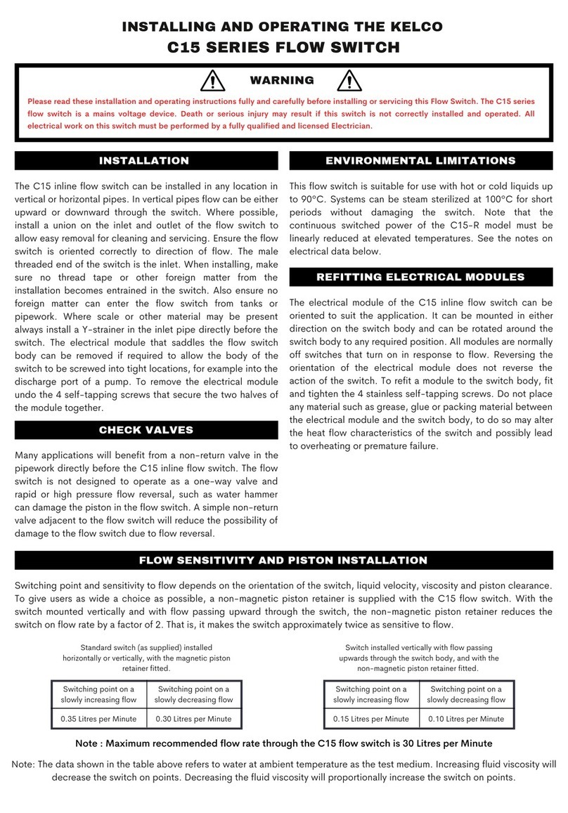
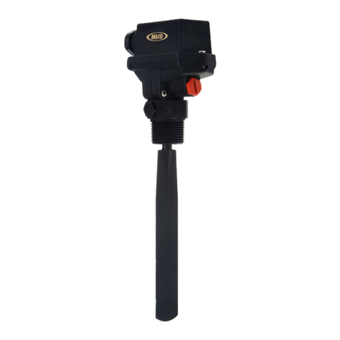
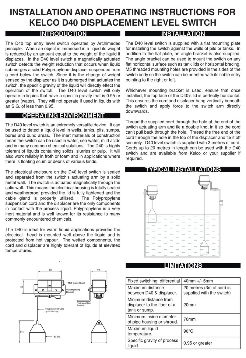
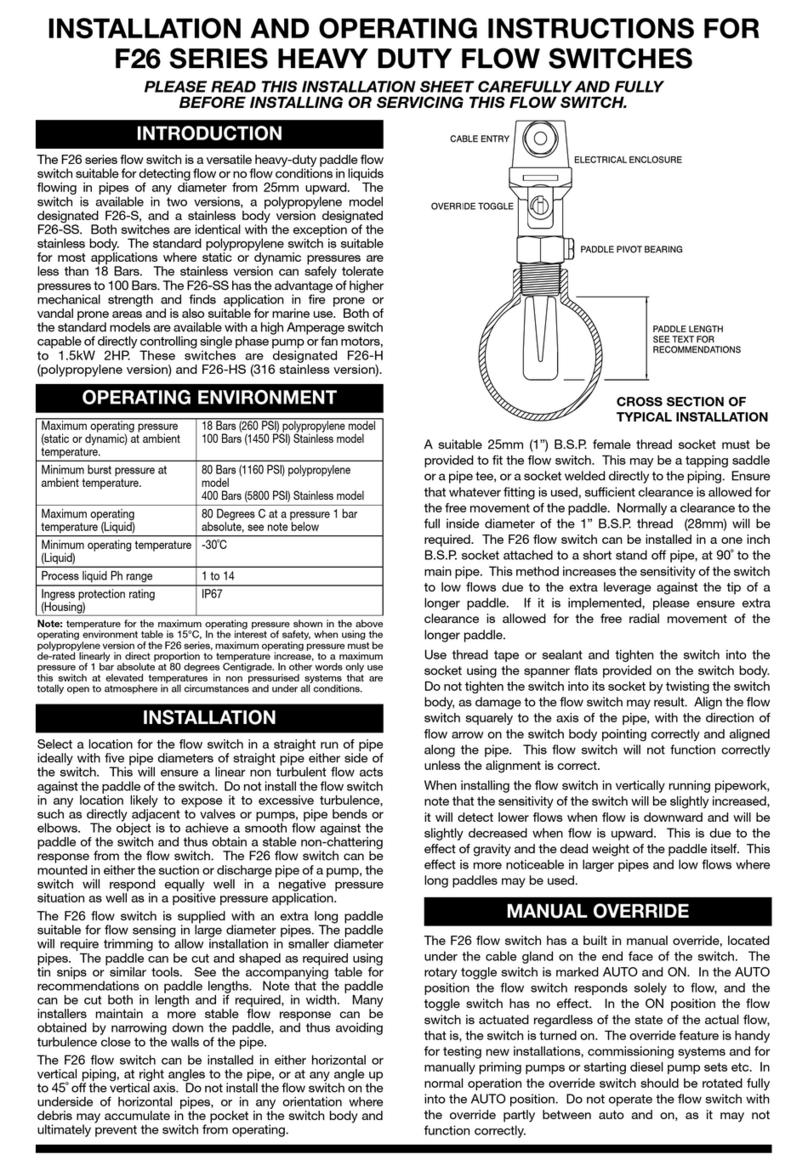
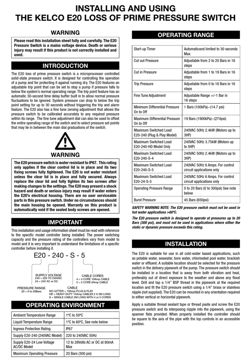
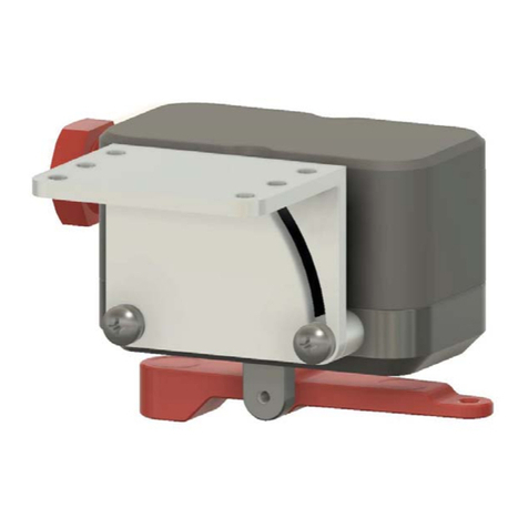
KELCO F29 Mk2 Assembly instructions

KELCO F29 Mk2
PROGRAMMABLE FLOW
SWITCH
INSTALLATION & PROGRAMMING
MANUAL
KELCO Engineering Pty Ltd
Sydney Australia
www.kelco.com.au
Version 070218

2
IMPORTANT: READ THIS FIRST
DO NOT EXPOSE THE F29 Mk2 TO VIBRATION. INSTALL ONLY IN
PIPEWORK THAT DOES NOT VIBRATE. Vibration will damage the
electronics within the F29 and will void your product warranty.
This F29 programmable flow switch has been fully tested and calibrated. It
is set to operate in a basic way with most of its special functions and
features switched off. On start up the F29 will run the pump using its start
up timer for up to 5 seconds. If it finds flow in the first 5 seconds it will
continue to run the pump. If flow is lost, the pump will continue to run for 5
seconds held on by the F29’s built in run-on timer. If flow fails to return, the
pump will be shut down after the run-on period. Pressing and releasing the
(R) reset button on the F29 or resetting the power will repeat this basic
process.
THE BUTTONS
The F29 is controlled and configured using 4 onboard buttons.
(R) Reset button. Stops the pump and restarts the F29 when released.
(˄) Up arrow button. For increasing program settings.
(˅) Down arrow button. For decreasing program settings.
(P) Programming button. For stepping through the menu and entering
settings into memory.
THE LIGHTS
The F29 includes 4 multicolour lights to indicate activity.
Flow: This light is GREEN when the F29 detects flow and RED when no
flow is detected.
Pump: This light is GREEN when a pump is running and RED when the
pump is stopped.
Timer: This light may be GREEN or RED when a timer or special function
is running.
Remote: This light is BLUE when remote input No. 1 is closed and off
when the remote is open. The light is RED when remote input No. 2 is
closed and off when the remote is open. This light is PURPLE when both
remote inputs 1 & 2 are closed.

3
LCD SCREEN BACKLIGHT
The LCD backlight can be turned on or off.
To turn the light off press and hold down the (˅)button. Press and release
the (R) button. Release the (˅)button. Repeat to turn the light on. The
light remembers the state it was last left in, if power is turned off. The light
can be left permanently on or off as required.
TEMPERATURE
The F29 monitors its internal temperature when running. Pressing the (˅)
button while the flow switch is powered up displays the current internal
temperature of the F29.
PRESS (and release) THE (P) BUTTON
When the F29 is powered up, pressing the (P) button, holding it down
for 1 second and releasing it takes you to the top of the menu. Pressing
and releasing the (P) button loads whatever the screen is displaying into
the F29’s memory. The memory is non-volatile and settings are retained
when power is off. You can exit the menu at any time by pressing and
releasing the (R) button. Any settings you have made up to that point will
be retained. There is no need to step all the way through the menu when
making a change to a setting.
INSTALLING THE F29
1) Do not install the F29 in an exposed outdoor location. The F29 is
weatherproof, however, to ensure a long reliable life we recommend
it be protected from direct exposure to the sun and rain. A skull cap
is provided with the F29 and we recommend it be used to protect the
F29 when direct observation of the LCD screen is not required.
2 ) Do not expose the F29-S to freezing. If the F29 is to be used in
areas where freezing conditions will be encountered, use the stainless
steel F29-SS and always lag the pipework for several metres either
side of the flow switch to prevent the adjacent pipework from freezing.
3) Do not use the standard thermoplastic F29-S flow switch in hot
water applications. The standard F29-S is not designed to be used in
water hotter than 60ºC. The stainless steel model can be used in
water up to 90ºC.

4
4) Do not expose the thermoplastic F29-S to static or dynamic
pressures greater than 18 Bars, 261 psi. Do not expose the stainless
steel F29-SS to static or dynamic pressures greater than 200 Bars,
2900 psi.
5) Do not install the F29 in a section of pipe that is subject to vibration.
Vibration will cause premature failure of the electronic components
within the F29.
LOCATION
Where possible install the F29 in a location that is sheltered from direct
exposure to the weather. The F29 is weatherproof and is supplied with a
protective cover. However, to ensure a long reliable life we recommend it
be protected from direct exposure to the sun and rain. Intense sun light will
eventually cause discolouration and degradation of the flow switch’s
housing. It is therefore advisable to protect the F29 from the weather if
possible.

5
The F29 should be installed in a straight section of pipe preferably with 5
diameters of straight pipe either side of the paddle. The F29 can be
installed in a suitable pipe socket, tapping saddle or pipe tee.
The F29 can be installed in either the suction or discharge pipework of the
pump. It is more common to install it in the discharge pipe, either before or
after the system’s air cell. If the system includes an air cell a decision must
be made as to which side of the air cell to locate the flow switch. The way
the overall system functions will depend on this decision.
BEFORE THE AIR CELL
If the F29 is installed before the air cell, it will only start the pump on
pressure drop via an external pressure switch since the initial draw off will
be supplied from the air cell and will not push the paddle of the F29 into its
on position. The only change in state the flow switch will see will be the

6
Controller
Discharge
Controller installed before the air cell
closing of the external pressure switch’s contacts on a falling pressure.
Choose this arrangement if you want to keep pump starts to a minimum
and you are prepared to accept the delay in starting associated with the
slow pressure fall from the air cell.
AFTER THE AIR CELL
If you install the F29 in the pipework after the air cell the flow switch will
start the pump each time flow from the air cell pushes its paddle forward or
each time pressure falls to whatever pressure you have set the external
pressure switch to start at. Choose this arrangement if you want the system
to deliver a steady pressure and to start each time flow is sensed.

7
INSTALLATION
The F29 is supplied as two separate assemblies, the paddle assembly
and the electrical housing. The paddle assembly should be installed in the
pipework first.
TRIMMING THE PADDLE
The paddle of the F29 can be cut down to suit the specific pipe size and
intended application. Cut the paddle using a hacksaw or tin snips so it
clears the sides of the pipe socket and protrudes approximately half to
two thirds of the way across the pipe when the controller is screwed into
the pipework. If a low flow rate is expected through the system the paddle
should be cut longer, perhaps until it only clears the bottom of the pipe by 3
to 5mm. If you are unsure as to what length the paddle should be, a paddle
trimming calculator is available at: -
http://www.kelco.com.au/paddle-trimming-calculator-2
Discharge
Controller
Controller installed after the air cell

8
If you know what the expected flow rate is the calculator allows you to
enter your pipe diameter and paddle dimensions. It will then determine if
the selected paddle dimensions are adequate for the application. Spare
paddles to suit the F29 Mk2 are available from Kelco or from your distributor.

9
FITTING THE PADDLE ASSEMBLY
To fit the paddle assembly into the pipework, apply Teflon tape or thread
sealing compound to the thread and use a suitable spanner and the
spanner flats provided on the paddle assembly (directly above the process
connection thread). Under no circumstances should the electrical housing
be twisted or used to screw the paddle assembly into the pipework or to
align the F29 with the axis of the pipework. To do so will irreparably damage
the F29 and void its warranty. When correctly installed there should be a
minimum 4mm gap between the top of the pipe socket and the top of the
thread on the F29. The F29 can be installed in either vertical or horizontal
pipe. The F29 has a 1” BSP or NPT process connection. A matching
female threaded socket, pipe saddle or pipe tee must be provided to fit the
F29 into the pipework.
ATTACHING THE ELECTRICAL HOUSING
There is a flat keying face on the cylindrical body of the paddle assembly
that keys the electrical housing onto the paddle assembly and aligns it
correctly. It is critical that the keying flat is on the downstream side and at
90 degrees to the axis of the pipework (see sketch). To secure the electrical
housing onto the paddle assembly an Allen head cap screw is supplied.
The cap screw should be screwed fully through the hole provided on the
underside of the electrical housing and should be securely tightened using
a 3mm A/F Allen key (supplied).
DETACHING THE ELECTRICAL HOUSING
To allow easy access to the flow switch’s paddle, the electrical housing of
the F29 can be detached from the paddle assembly. Removing the
electrical housing allows access to the paddle without the need to disconnect
the electrical connections to the F29. To remove the electrical assembly,
switch off the system’s power and undo and completely remove the locking
screw (see diagram). Once the locking screw is removed, lift the electrical
housing straight off (do not twist it when doing this). Once the electrical
housing has been removed, the paddle assembly can be unscrewed from
the pipework using the spanner flats on the body of the assembly. Simply
reverse this procedure to refit the electrical housing to the F29.
SENSITIVITY ADJUSTMENT
Under the end of the electrical housing on the F29 is a red hexagonal dust
cap. If you remove this dust cap you gain access to an adjustment screw

10
that allows the paddle preload to be reduced. As supplied the sensitivity
adjustment screw is wound fully in. In this position the paddle is at its least
sensitive. In this position it takes a substantial force from the moving water
to move the paddle. If you take a straight bladed screwdriver and wind the
sensitivity adjustment screw anti-clockwise (outward) the force against the
paddle that resists flow will be reduced.
The paddle will become increasingly more sensitive and will respond to
progressively lower flows the further out you wind the adjusting screw. The
total adjustment range is 10 turns of the screw. If you wind the adjustment
screw out beyond 10 turns there will not be enough residual force to return
the paddle to the off position when flow stops.
The range of sensitivity adjustment will also be affected by the orientation
of the F29. In horizontal pipework with the F29 mounted vertically the
useable range of adjustment is approximately 8 turns. In vertical pipe with
flow upwards, the full 10 turn range can be utilised.
ELECTRICAL INSTALLATION
INTRODUCTION
When used with its HD terminal link in place, the F29 can directly control
single-phase pump motors to 2.4kW via its relay 1. No interposing contactor
is required for such applications. The F29 can also be used to control 3
phase pump motors of any size via an appropriate interposing contactor.
WARNING
All electrical work associated with the F29 must be
carried out by qualified electrical personnel and all
electrical work must conform to AS/NZ standards and to
local wiring rules.

11
WARNING: The contactor control circuit must never exceed 240VAC.
Never series connect the F29 relay contacts and contactor coil directly
across 2 phases.
The F29 requires a stable 220V to 240V AC supply when operated from
the mains. It can also be operated from an 18 to 24V AC or DC supply by
utilising the low voltage active terminal FELV and neutral terminal N (see
the included wiring diagrams). When operated from a low voltage DC
supply the terminals FELV and neutral N are not polarity sensitive. Pay
attention to cable sizes and ensure cables are adequate for the specific
pump motor load. This is particularly important where long cable runs
are to be used in the installation. If the voltage drop associated with the
starting of the pump motor is excessive the F29 may repeatedly reset and
not operate properly.
THE HD (Heavy Duty) TERMINAL
The F29 contains a solid-state switch (HD Heavy Duty drive) that can be
used to protect the contacts of Relay 1 by eliminating the destructive arcing
caused by the starting and stopping of pump motors. The solid-state switch
is accessible from the HD terminal on the terminal block. We recommend
the HD drive be used whenever the controller is used to directly control
a single-phase pump motor. The HD drive should not be used when the
F29 is connected to a contactor, external timer, low wattage relay or to
any other external device where voltage free contacts are required. It is
strictly intended for the direct control of highly inductive AC motor loads.
The HD terminal and the controller’s built in relays must never be directly
connected to a DC motor under any circumstances.
When the HD terminal is linked to the normally open terminal of Relay
1, the HD drive in effect parallels a 42 Amp solid state switch across the
relay’s normally open contacts. This increases the momentary current
carrying capacity of the relay’s contacts to well over 60 Amps. The solid-
state HD drive is only activated for a brief period when the pump starts and
stops. It effectively handles the high inrush current associated with the
pump starting, and it provides a current path for the destructive back EMF
associated with the pump motor stopping.

12
To use the HD drive, place a heavy link wire between the HD terminal
and the Normally Open terminal of Relay 1.
BROWNOUT OR BLACKOUT
If a blackout or brownout occurs the F29 will not retain any memory of
where in its run or stop cycle it may have been, it will simply shut down the
pump. When power resumes, the F29 will reboot, restart the pump and run
any timer settings from the beginning. A manual reboot can be done at any
time by pressing and releasing the F29’s reset button.
CABLES
The F29 has 3 X M20 cable glands. As supplied, the cable glands are
blanked off with rubber plugs. To use the glands first remove one of the
rubber plugs and assemble the (supplied) cable gland bush and backing
washer into the cable port. The cable glands can accept cable from 7 to
9mm diameter. See sketch for assembling the cable gland components.
The F29 is supplied with a set of steel crimp rings. The crimp rings are to
provide strain relief for the controller’s cables. To use the crimps, place
one on the cable approximately 3 to 4mm below the end of the cables outer
sheathing. Crimp the two ears of the ring flat using bull nosed pliers. Pull
the cable back through the cable gland until the crimp ring’s ears are fully
located into the slots in the cable gland housing. Always leave unused
cable glands sealed off using the (supplied) rubber plugs.
The HD terminal must be left unused or only ever linked to Relay 1
Normally Open. It must never be used for any other purpose and it
must never be connected to any external device. Under no circumstances
connect the HD terminal to the terminals of Relay 2. The HD terminal
must be regarded as live at all times and at full mains potential.
WARNING

13
ELECTRICAL LIMITS
POWERING THE F29
The power required to drive the F29 depends on the nature of the supply,
AC or DC and on temperature. The table below gives the maximum power
required from various supplies at 25C. As temperature increases, the
power required will reduce. For example, at 30C the power requirement
will be approximately 3% less than the values given in the table. The
measurements expressed in the table represent the maximum required
power with both relays 1 and 2 closed and the LCD backlight and all
indicator lights on.
VOLTAGE LIMITS ON TERMINALS FELV & N
Maximum Supply Voltage 25VAC or 25VDC
Minimum Supply Voltage 18VAC or 18VDC
VOLTAGE LIMITS ON TERMINALS A & N
Maximum Supply Voltage 260VAC
Minimum Supply Voltage 190VAC
Rubber Plug
Backing Washer
M20 Gland Nut
Plug unused cable glands
using the rubber plugs
(supplied). Fully tighten
the gland nut to seal the
unused cable port.
Crimp the ears of the
strain relief ring onto the
cable and pull the cable
back into the slots in the
gland housing.
Cable 7mm to 9mm diameter
Controller Housing
Rubber Grommet Backing Washer
4mm

14
RELAYS
The F29 houses 2 relays. Relay 1 has S.P.D.T contacts. Relay 2 has
S.P.S.T normally open contacts. Relay 1 is normally regarded as the
pump control relay and relay 2 is normally regarded as the alarm relay.
With the HD terminal linked to the NO terminal of Relay 1, the F29
can directly control a single phase motor up to 2.4kW via its NO
contacts. Without the HD terminal link in place, relays 1 & 2 are
limited to directly controlling a motor to 0.75kW. Both relays can
control motors of any required size via interposing contactors.
POWER REQUIRED TO DRIVE THE STANDARD F29
24VDC Supply to FELV & N Maximum 68mA 1.63Watts
24VAC 50Hz Supply to FELV
& N
Maximum 108mA 2.34Watts
220VAC 50Hz Supply to A & N Maximum 87mA 2.00Watts
240VAC 50Hz Supply to A & N Maximum 94mA 2.54Watts
POWER REQUIRED TO DRIVE THE 12VDC F29-12
With Both Relays Closed 68mA Max at 12VDC 0.81W
With One Relay Closed 52mA Max at 12VDC 0.62W
Quiescent State (relays open) 25mA Max at 12VDC 0.30W
CONTACT RATINGS FOR RELAYS 1 & 2
16A at 240VAC Resistive Load PF > 0.9
16A at 30VDC Resistive Load PF > 0.9
50mA at 5VDC Minimum Load
MAXIMUM PUMP MOTOR LOAD FOR RELAY 1
10A at 240VAC 2.4kW Inductive Motor Load
IMPORTANT: When directly controlling a pump motor through relay 1,
always link the HD terminal to relay 1 Normally Open terminal and make
sure the maximum switched motor current never exceeds 10 Amps. On a
pump motor P1 must not exceed 2.4kW.

15
REMOTE INPUT
WARNING: The low voltage source available at the FELV terminal is
non-isolated and must be regarded as operating at full mains potential
whenever the F29 is powered from the mains. FELV means Functional
Extra Low Voltage and refers to a non-isolated extra low voltage
source.
An external switch with voltage free contacts such as a pressure switch,
tank level switch or a set of external relay contacts can be used to control
the F29. The supply to the external switch must be taken from the FELV
terminal of the F29 when the controller is powered from the mains or from
a 24V source. The F29 must always be powered from the same source
as the supply to external switch. The supply to the remote switch on the
F29-12 (low voltage DC model) must be taken from the supply positive
terminal. In all cases the external switch return wire must be connected
to the Remote input (R) terminal on the F29. The supply to the external
switch will range from 12 to 24 VDC or from 20V to 35V AC depending on
the supply voltage.
WARNING: Never connect an external power source of any kind to
the F29’s remote input terminal.
The remote switch can be installed some distance from the F29. The
maximum distance is limited by cable resistance and capacitance. The
total cable resistance must not exceed 5K Ohms with the remote switch
closed. The total capacitance of the cable must not exceed 25nF with the
remote switch open. Wires to the remote switch should be run separately
from power carrying cables. Do not run the remote switch wires in a conduit
that also contains power cables. Capacitive coupling between the adjacent
cables may cause false triggering of the F29’s remote input. For cable
runs longer than 150 metres we suggest using 2 separate wires to reduce
capacitive coupling between the adjacent wires. When set up this way
cable resistance becomes the limiting factor for distance. The table below
sets out the resistance of typical copper wire of various diameters.
Note that the cable resistance refers to the total resistance out to the
remote switch and back, as measured at the controller across the 2 remote
connection wires with the external remote switch closed.

16
EXAMPLE
A water tank is located 2000 metres from the F29. Two separate wires each
0.2mm^2 are run to the remote tank (total wire length is 4000 metres). The
resistance as measured across the 2 wires back at the F29 (with the tank
level switch closed) is 382 Ohms. This is well under the 5,000 Ohm limit.
The remote input to the F29 will operate properly provided the wires are
separated by sufficient distance that the capacitance between them is less
than 25nF. Capacitance should be measured between the wires when the
remote switch is open and it must be less than 25nF.
Cable Size square mm Resistance Ohms /1000M
0.2 95.30
0.5 36.20
0.75 24.13
1.0 18.10
1.5 12.10
Note: Use table as a guide only, cable resistance may vary depending on
the wire standard and construction.

17
WIRING DIAGRAMS
PLUG & PLAY CONNECTIONS
CONNECTIONS FOR A SINGLE PHASE PUMP
PLUG AND LEAD WIRING
All electrical wiring associated with
this controller must be carried our by
a qualified electrician
Optional voltage free
external input
Earth Link
Remote switches with
NO or NC voltage free contacts
This link wire must be used whenever
the controller is directly controlling a single
phase pump motor, as shown. Do NOT use the
HD link in 3 phase or single phase control circuit
applications
Active
Pump Motor 1
110 ~ 240VAC 50/60Hz Pump Motor 2.4kW
Max. when the HD terminal is linked
Neutral
Supply
110 ~ 240VAC 50/60Hz.
Audible or Visual Alarm

18
Remote switches with
NO or NC voltage free contacts
This link wire must be used whenever
the controller is directly controlling a single
phase pump motor, as shown. Do NOT use the
HD link in 3 phase or single phase control circuit
applications
Pump Motor 2
Single Phase 110 ~ 240VAC Motor
0,75kW Max. when controlled directly
through relay 2, as shown.
Active
Pump Motor 1
110 ~ 240VAC 50/60Hz Pump Motor 2.4kW
Max. when the HD terminal is linked
Neutral
Supply
110 ~ 240VAC 50/60Hz.
DUAL SINGLE PHASE PUMPS & 2 REMOTE INPUTS
LOW VOLTAGE SUPPLY
Negative
Positive
Supply
18 to 24 Volts AC or DC

19
BASIC 3 PHASE PUMP CONTROL
3 Phase Pump Motor
N
L3
L2
L1
Contactor
WARNING
Contactor coil rating must not
exceed 240VAC
DUAL 3 PHASE PUMP CONTROL
3 Phase Pump Motor 1
N
L3
L2
L1
3 Phase Pump Motor 2
WARNING
Contactor coil rating must not
exceed 240VAC
Contactor 1
Contactor 2

20
3 PHASE CONTROL WITH ALARM & REMOTE INPUT
Remote switch
with NO or NC
voltage free contacts
Three Phase Pump Motor
Alarm
16A 240V Maximum
resitive load
N
L3
L2
L1
Contactor
WARNING
Contactor coil rating must not
exceed 240VAC
THE 12VDC F29 FLOW SWITCH
A low voltage DC version of the F29 Mk2 is available for battery operation
and for use in solar pumping systems. Functionally the 12V DC model is the
same as the mains voltage model except for the terminal block markings.
On the 12VDC model the active and neutral terminals are replaced by a
positive + and a negative – terminal. Supply voltage across the positive
and negative terminals must never exceed 24VDC or the flow switch will be
damaged. The supply terminals are reverse polarity protected, however,
the flow switch will simply not operate unless the supply polarity is correct.
If a remote switch is connected to the 12V DC F29 the supply to the remote
switch must be taken from the positive terminal on the F29. The remote
switch and its connecting circuit will then operate at 12VDC.
Table of contents
Other KELCO Switch manuals

KELCO
KELCO E30 Mk2 Assembly instructions

KELCO
KELCO F29 Installation manual

KELCO
KELCO ub25 User manual

KELCO
KELCO D40 User manual

KELCO
KELCO E30 Assembly instructions

KELCO
KELCO E20 Series Instruction Manual

KELCO
KELCO E30 Installation manual

KELCO
KELCO D50 Use and care manual

KELCO
KELCO F21 Series Wiring diagram

KELCO
KELCO C15 Series Wiring diagram