INSTALLING AND OPERATING THE KELCO F21 SERIES FLOW SWITCH
INTRODUCTION
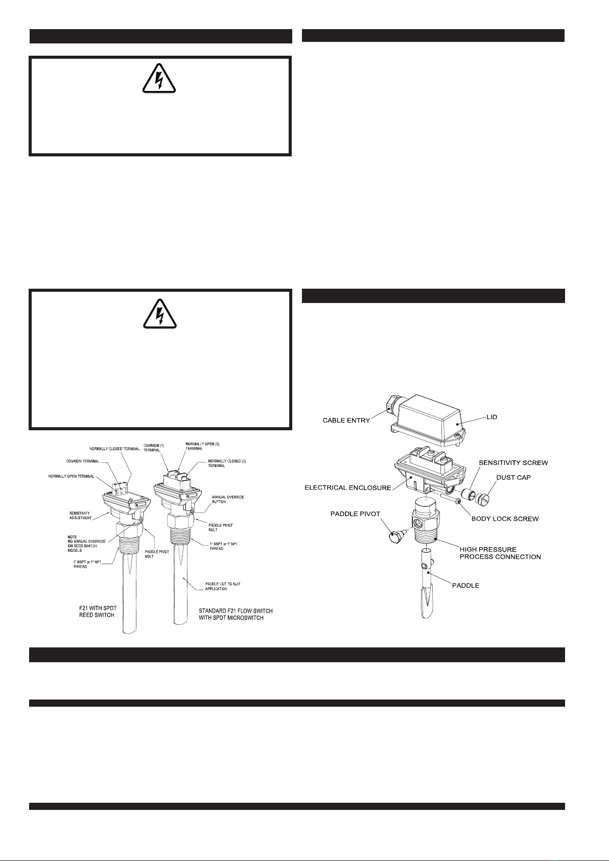
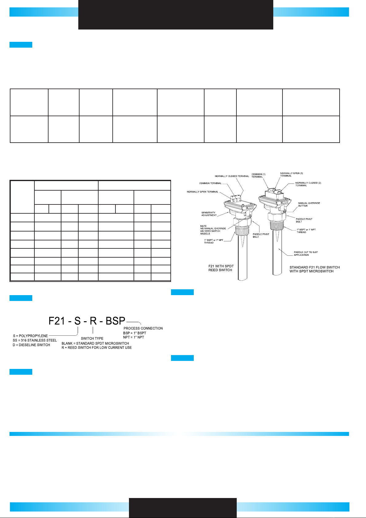
This F21 ow switch may have been supplied in one of several available congurations. The model number of the specic switch is located inside the lid of the electrical housing. The
F21 series ow switch is a versatile heavy-duty paddle ow switch suitable for detecting ow of liquids in pipes of any diameter from 25 mm (1”) upward. This ow switch has several
unique features: A) The complete electrical assembly can be removed from the switch by undoing and removing the locking screw in the split clamp on the side of the switch’s electrical
housing. With the locking screw removed, the electrical housing can be pulled straight off the wet end of the switch. Removing the electrical housing allows the wet end of the switch
to be unscrewed from pipework without disturbing the cable connection to the switch. This means the paddle of the switch can be changed, inspected or trimmed without the need to
disturb the electrical connection to the switch. replace and tighten the locking screw after completing any work on the wet end of the switch. B) The standard version of the F21 ow
switch has a built-in manual override. On the end of the switch body underneath the cable entry port is a spring loaded push button. Pressing this button actuates the switch, regardless
of the state of ow. Pumping systems can be manually started by pressing this button and holding it in until ow is established. The override button can be used to test control circuits
and wiring during commissioning, without the need for water in the pipework. The button is spring loaded so it can’t be inadvertently left in the on position and only overrides the ow
switch while it is pressed.
Warning note on operating limitations: Maximum operating pressure of the Polypropylene F21-S must be linearly de-rated as operating temperature is increased so that at 60°C
the maximum permissible operating pressure for the switch is not more than one Bar Absolute.
INSTALLATION
OPERATING LIMITATIONSELECTRICAL DATA MICROSWITCH MODELS
Model F21-S
(All Poly)
F21-SS
(Stainless)
F21-D
(Diesel)
Maximum operating pressure
(Static or Dynamic) at ambient
temperature
18 Bars
(261 PSI)
200 Bars
(2900 PSI)
200 Bars
(2900 PSI)
Minimum burst pressure at
ambient temperature
45 Bars
(652 PSI)
500 Bars
(7251 PSI)
500 Bars
(7251 PSI)
Maximum operating
temperature
60ºC
See note
below
80ºC 80ºC
Minimum operating
temperature
0ºC 0ºC 0ºC
Minimum liquid S.G. 0.8 0.8 0.8
RATED
VOLTAGE
NON INDUCTIVE LOADS INDUCTIVE LOADS
RESISTIVE
LOAD
LAMP LOAD INDUCTIVE
LOAD
MOTOR LOAD
NO NC NO NC NO NC NO NC
125 VAC 15A 3A 1.5A 15A 5A 2.5A
250 VAC 15A 2.5A 1.25A 15A 3A 1.5A
500 VAC 10A 1.5A 0.75A 6A 1.5A 0.75
8 VDC 15A 3A 1.5A 15A 5A 2.5A
14 VDC 15A 3A 1.5A 10A 5A 2.5A
30 VDC 6A 3A 1.5A 5A 5A 2.5A
125 VDC 0.5A 0.5A 0.25A 0.05A 0.05A 0.05A
250 VDC 0.5A 0.5A 0.25A 0.03A 0.03A 0.03A
SWITCH
TYPE
CONTACT SWITCHED
POWER
SWITCHED VOLTAGE
MAXIMUM
SWITCHED CURRENT
(RESISTIVE)
CARRY
CURRENT
BREAKDOWN
VOLTAGE
TYPICAL
APPLICATIONS
DRY CONTACT
REED SWITCH
S.P.D.T BREAK
BEFORE MAKE
20W / VA
MAXIMUM
140V AC
150V DC
1 AMP
MAXIMUM
2 AMP
MAXIMUM
200V MINIMUM PLC, TELEMETRY & GENERAL
LOW VOLTAGE CONTROL
APPLICATIONS
The reed switch models are supplied with a high compliance single pole double throw reed switch suitable for all low wetting current and low voltage applications. Such
applications include PLC control, signalling in telemetry systems and relay logic circuits. Note: the reed switch models are not suitable for use with inductive loads such as
contactors or high wattage relays.
ELECTRICAL DATA REED SWITCH MODELS
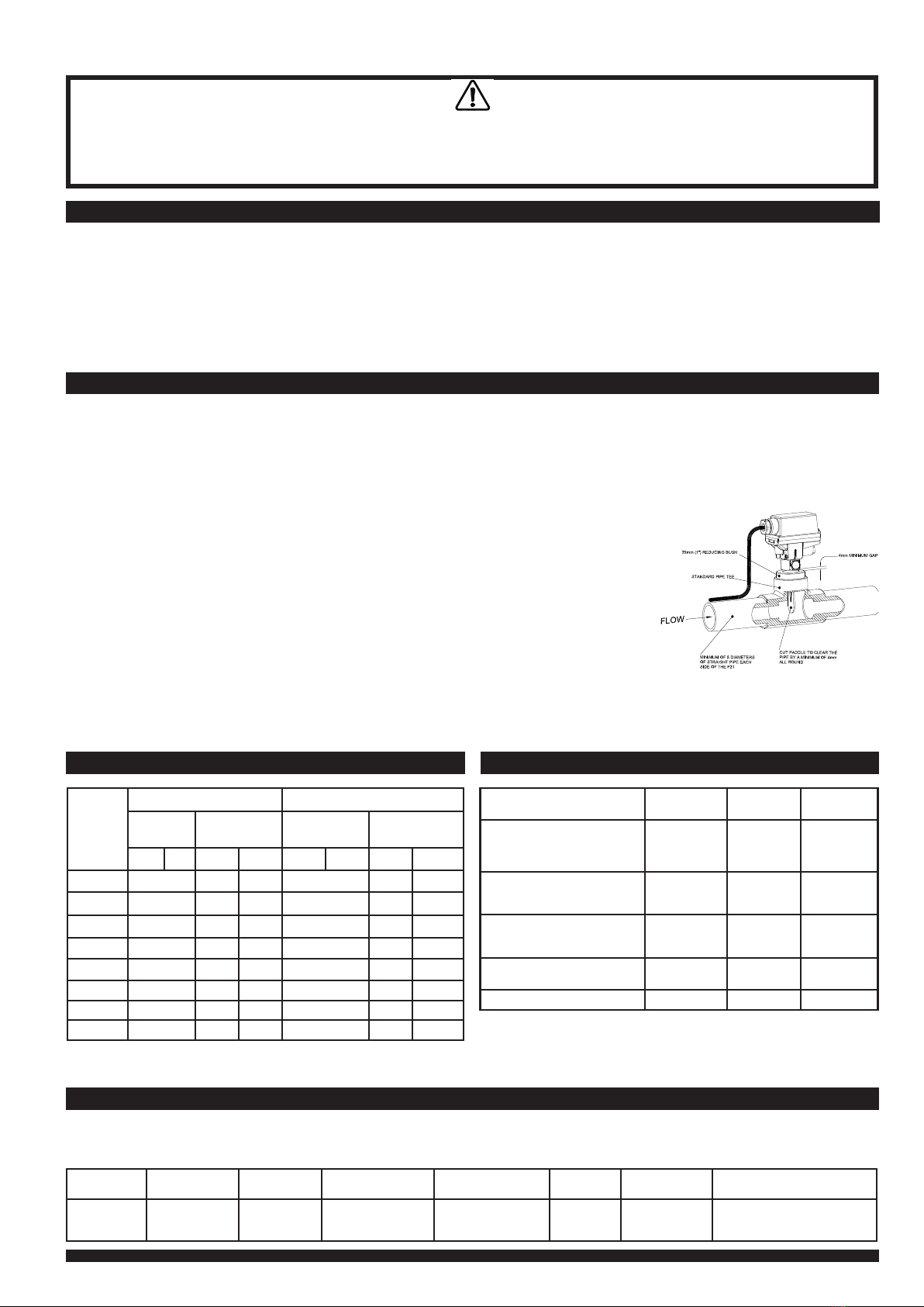
Select a location for the ow switch in a straight run of pipe, ideally with ve pipe diameters of straight pipe either side of the switch. This will ensure a linear non turbulent ow acts
against the paddle of the switch. Do not install the ow switch in any location likely to expose it to turbulence, such as close to valves, pumps or pipe bends The idea is to install the
switch in a location where there is a smooth ow of liquid past the paddle, and to obtain a stable non-chattering response from the ow switch. The F21 ow switch can be mounted in
either the suction or discharge pipe of a pump, the switch will work equally well in positive or negative pressure applications.
The F21 ow switch has an extra long paddle so it can be used in large diameter pipes. The paddle will require trimming if the ow
switch is to be used in smaller diameter pipes. The paddle can be cut and shaped as required using tin snips or a hacksaw. Note, the
paddle can be cut both in length and if required, in width. Many installers maintain a more stable ow response can be obtained by
narrowing down the paddle and avoiding turbulence close to the walls of the pipe. The F21 ow switch can be installed in any required
orientation except on the under side of horizontal pipes.
Depending on the thread on the switch, a 25 mm, 1” BSP or 1” NPT threaded socket must be provided on the piping, to t the ow
switch. This may be a tapping saddle or a pipe tee tted with a threaded reducing bush, or a socket welded directly to the pipe. Ensure
that whatever tting is used, sufcient clearance is allowed for the free movement of the paddle. Normally a clearance to the full inside
diameter of the 1” pipe thread will be required. The F21 ow switch can be installed in a 1” pipe socket attached to a short stand off
pipe, at 90° to the main pipe. This method of mounting increases the sensitivity of the switch to low ows due to the extra leverage
against the tip of a longer paddle. If this mounting method is used make sure to leave extra clearance to allow for the full arc movement
of the longer paddle.
Use a suitable thread sealant and tighten the switch into the socket using the spanner ats provided on the switch body. Do not tighten
the switch into its socket by twisting the electrical housing of the switch, as damage to the ow switch may result. Align the ow switch
squarely to the axis of the pipe, with the direction of ow arrow on the side of the switch body parallel to the axis of the pipe and aligned
in the direction of ow. The F21 will not function correctly unless alignment is correct. When installing the ow switch in vertically
aligned pipework, the sensitivity of the switch will be slightly increased; it will detect lower ows when ow is downward, and the
sensitivity will be slightly decreased when ow is upward. This is due to the effect of gravity on the dead weight of the paddle itself.
This effect is more noticeable in larger pipes and low ows where long paddles may be used.
WARNING
Please read these installation and operating instructions fully and carefully before installing or servicing this level switch. The F21 Series ow switch is
mains voltage device. Death or serious injury may result if this switch is not correctly installed and operated. All electrical work must be performed by
a fully qualied and licenced electrician.
Vendor Manual - Heavy Duty Flow Switch - Kelco - Model F21 - Installation Operation and Maintenance Manual