Keller HP Series User manual

HigH-Pressure-Calibrator
standard- and Full-Version
KELLER
May 2006

Included In delIvery:
HIgH Pressure calIbrator
standard-versIon
– 1 Calibrator
– 1 Carrying Case
– 1 Test-Unit Adapter G 1/4” / G 1/2”
– 1 Test-Unit Adapter G 1/4” / G 1/8”
– 1 Spare Battery (3,6 V)
– 1 Allen Wrench
– 1 Manual
– 1TestCerticate
… in addition for version with
Logger-Option:
– K101-Cable (RS 232)
– 2 Program Discs:
• Logger Windows
• Logger MS-DOS
Included In delIvery:
HIgH Pressure calIbrator
Full-versIon
– 1 Calibrator
– 1 Carrying Case
– 1 Test-Unit Adapter G 1/4” / G 1/2”
– 1 Test-Unit Adapter G 1/4” / G 3/8”
– 1 Pressure Switch Adapter
– 1 Adapter (4…20 mA / 0…20 mA)
– 1 Adapter (0…10 V / 0…20 V)
– 1 Mains Adapter
– 1 Spare Battery (3,6 V)
– 1 Allen Wrench
– 1 Manual
– 1TestCerticate
… in addition for version with
Logger-Option:
– K101-Cable (RS 232)
– 2 Program Discs:
• Logger Windows
• Logger MS-DOS

lIst oF contents:
Outline Drawing 1
General Description 2
Operating the Calibrator 3
– Turn-On
– Connecting Test-Units
– Executing Functions and Commands
– Pressure Generation
– Turn-Off
Description of the Functions 4
Measuring Mode 5
– Mano-Mode
Temporarily Setting new Zero Reference 6
– tara-Mode
Selection of Pressure Unit 6
– unit-Mode
Preparing the Leak-Test 7
– leak-Mode
Executing the Leak-Test 8
– leak-Mode
Testing of Pressure Switches* 9*
– Pst-Mode*
Preparing Storage of Measured Values 11
– reC-Mode
Executing Storage of Measured Values 12
– reC-Mode
Measuring the Linearity* 13*
– lin-Mode*
Calculating the Linearity* 14*
– lin-Mode*
Adjusting the Display-Resolution 15
– reso-Mode
Permanently Setting new Zero Reference 15
– Zero-Mode
Data Transfer to PC 16
Maintenance 17
– Priming the Pressure System
– Testing of Battery Capacity
– Battery Change
– Restarting the Calibrator
– External Supply of Test-Units
– Overow/OverpressureLimit
– Service
Operating Guide/Functions 18
Technical Data 19
Declaration of Conformity 20
* Full-Version only

1
outlIne drawIng
max. Oil-Level
KELLER
KELLER
10 12 13 14
11a
9815
7
6
5
4
32
1b
1a
11b
1a) Connector for RS 232 Output
(Standard Version)
1b)* Connector for RS 232 Output
(Full-Version)
2) Instrument Base (with battery compartment*)
3)* LED-Diode
4) HOLD-Key (H-Key)
5) Shut-off Valve
6) Display
7) Function-Key (F-Key)
8) Oil Chamber
9) OilRellScrew
10) Oil Screw Compressor
11a) Outlet Pressure Port (G 1/4”, female)
with Hexagon Plug (200 bar and 350 bar
Calibrator with Overpressure Valve)
11b) Outlet Pressure Port (G 1/4”, female)
with Hexagon Plug (700 bar Calibrator
without Overpressure Valve)
12) Priming Pump
13)* Input Plug for external Power Supply to
Transmitter/Switch under Test
14)* Electrical Connection for Test-Unit Adap-
ters (Transmitters or Pressure Switches)
15) Return Pipe
High-Pressure-Calibrator Ranges: 200 bar, 350 bar, 700 bar (Sealed Gauge)
* Full-Version only

2
general descrIPtIon
The calibrator combines a number of functions
and performance features. Please take your
time reading this manual thoroughly prior to
setting the calibrator into operation. The safety
instructions on page 17 are meant to enhance
your safety and to maintain the functions as well
as the accuracy of the calibrator and its internal
sensor.
The instrument is battery powered, thus very
well suited for outdoor use.
The calibrator itself is powered by a 3,6 V
battery. Test-units (transmitters or electronic
switches) can either be powered by the internal
9 V batteries or external power supply.*
The high pressure calibrator generates pressure
with both the integrated priming pump and the
oilscrewcompressor.Thepressurecanbene
adjusted.
The high technology integrated in this instru-
ment allows it to measure precisely both the
pressure generated and the output signal of a
test-unit connected.
Thus, test-units can be measured and their
characteristics can exactly be documented.
The calibrator has an internal memory for recor-
dingdata.Itcaneitherbelledwiththelinea
rity measurements (function lin)*, the switching
points of a pressure switch (function Pst)* or
with continuously measured recordings. This
data can later be transferred to a PC for evalua-
tion via RS 232 serial interface.
The calibrator is operated with the function key
(F-key), marked by a pointed triangle.
An additional key, the Hold-key, will freeze the
display at any time during operation.
* Full-Version only

3
oPeratIng tHe calIbrator
turn-on
The calibrator is turned on by pressing the func-
tion key once.
connectIng test-unIts*
Adapter:
Included in the delivery of the calibrator are
different test-unit adapters, one for each of the
following transmitter types:
– 4…20 mA / 0…20 mA transmitter
– 0…10 V / 0…20 V transmitter
– Pressure switch
Plug the test-unit adapter into socket 14.
electrIcal connectIon oF test-unIt*
Select the correct adapter. Wire the transmitter/
switch under test to the adapter. Check that
polarity is observed and that good connections
are made.
Pressure connectIon For tHe test-unIt**
Your test-unit can be connected with the
calibrator via the pressure connection 11a resp.
11b.
Pressure generatIon
Attention: To avoid an overpressure within the
oilchamber,theoilrellscrew(9)mustbeopen
when operating the calibrator!
Generate pressure with the priming pump (12)
up to approx. 10 bar.
Increase or reduce pressure with screw com-
pressor (10).
decreasIng tHe Pressure
1) To return pressure to zero, completely
screw back compressor (10).
2) Open shut-off valve (5).
Do not open (5) when system is under high
pressure! (Especially when using an external
pres
sure source, damage/injury may result).
If you are not able to reach the desired pressure,
read the chapter “Maintenance” on page 17 on
how to completely prime the pressure system.
executIng FunctIons and commands
Read the following chapter to get acquainted
with the functions.
turn-oFF
Press the function key until the command oFF
appears on the display. Release the key imme-
diately and the instrument turns off.
** To avoid leakage and damage of the check valve, the test-unit has to be cleaned prior to connecting it to the
calibrator.

4
descrIPtIon oF tHe FunctIons
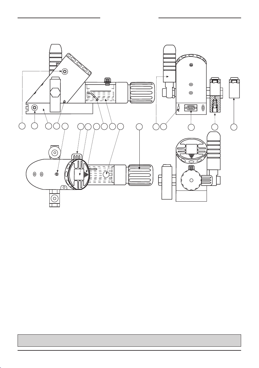
For a better understanding, the operating ele-
ments are described again:
FunctIon-Key (F-Key)
The function key on the front of the instrument,
marked by a pointed triangle, serves to operate
the instrument.
Hold-Key (H-Key)
The Hold-Key, integrated in the back of the
instrument housing, freezes the values during
the Mano-Mode. It has additional functions in
other modes (see following pages).
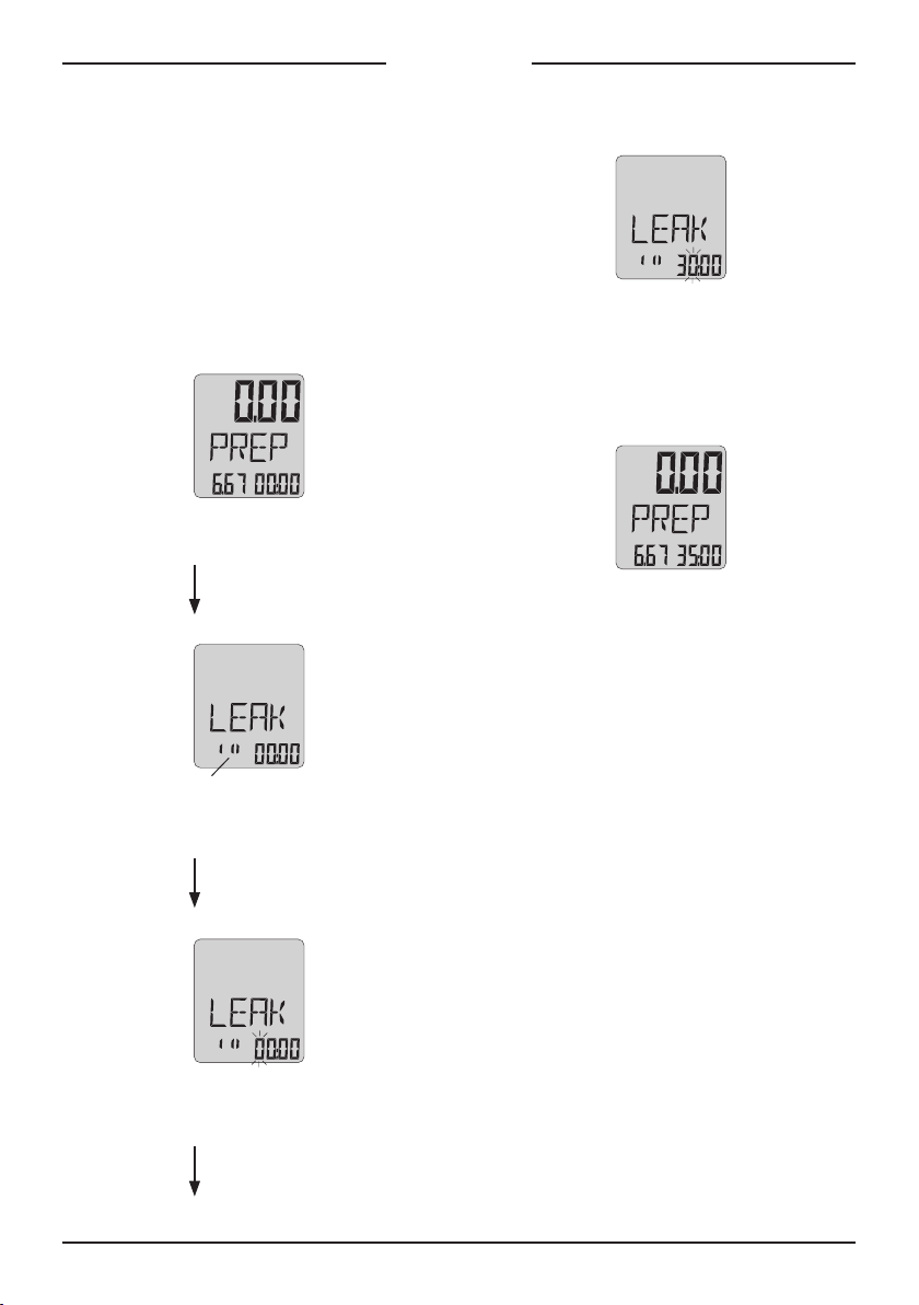
command structure
When keeping the F-Key pressed, the functions
exe, oFF, Mano, tara, unit, leak, Pst*, reC, lin*,
Zero, reso and ascending numbers appear suc-
cessively on the display. Releasing the F-Key at
a displayed function activates and leads into the
function. This cycle (constantly pressing the F-
Key and letting it go at a desired function) is cal-
led activation (e.g. to activate Mano --> Press
F-Key until display shows Mano --> Release the
F-Key).
Withinspecicfunctions,theFKeycanexecute
additional commands (exe, steP, reset).
Activating oFF turns off the instrument. When
starting the instrument again, the display will
automatically lead into the function from which
the instrument was previously turned off.
Activate Mano if normal operation is desired.
exe:In Mano-Mode: To reset peak- and
trough-pressure.
oFF:To turn off the instrument.
mano:To display the actual pressure
generated, the units, peak- and
trough pressure.
tara:To set a new, volatile reference for
the zero point (Tare).
unIt:To display the pressure in different
units (bar, Psi, kPa, MWC…).
leaK:To measure the pressure changes
over a programmable time.
Pst*: To test pressure switches.
rec:To record the measured values in
programmable intervals.
lIn*: To determine the linearity of a
test-unit.
reso:To reduce the resolution by
factor 10 or to return to the
original resolution.
Zero:To write a new zero point into the
non-volatile memory.
28, 29… Ascending numbers (have no
function).
* Full-Version only

5
mano-mode
The Mano-Mode is the standard mode of the ca-
librator. In this mode, the calibrator shows on
the upper display the actual pressure generated.
The smaller displays below indicate the peak-
and trough values. The measured values on the
smaller displays always appear with a reduced
resolution. Activating exe resets the peak- and
trough values, meaning that they are reset to the
actual pressure.
Full-Version only: If a transmitter is connected,
the display automatically indicates the value
of the transmitter in mA or V on the lower left
display. The lower right display shows the tem-
perature.
Pressing the Hold-Key (H-Key) freezes the
measured values. The actual pressure is now
shown on the lower right display. Pressing the
H-Key again leads back into the Mano-Mode
with the peak- and trough values reset to the
actual pressure (same as exe).
mano-mode
disPlay WitHout transMitter
= Is being read as a “1” between 100 bar and 200 bar when displaying with increased resolution --> 133.41 bar
Actual
Pressure
TroughPeak
Activate ExE
Actual
Pressure
TroughPeak
Press H-Key
Hold-mode
Frozen
Value
Actual PressurePeak
With H-Key back to
MAno-Mode
mano-mode
disPlay WitH transMitter (Full-Version only)
Actual
Pressure
Temperature of
the Reference-
Sensor
Signal of
Transmitter
Press H-Key
Hold-mode
Frozen
Value
Actual
Pressure
Frozen Value
of Transmitter

6
tara-mode / unIt-mode
The tara-Mode serves to set a temporary zero
reference. Unlike to the Zero-Mode, this new
zero reference will not remain after the instru-
ment has been turned off.
Activate tara:
Value to be
set to zero
Actual
Pressure
Activate ExE
mano-mode
With the command exe the new zero is being
determined and stays as a reference until a new
tara is being executed or until the instrument is
turned off.
The program returns to the Mano-Mode.
The unit-Mode allows the selection of one of
four pressure units.
Activate unIt:
Activate ExE
Activate ExE
Activate ExE
Activate Mano to return to the Mano-Mode with
the new selected unit.
Please note that, depending on pressure range,
the units can differ from the above.

7
leaK-mode
The leak-Mode serves to measure a pressure
change over a programmable time. The unit to
be tested has to be connected to the calibrator.
Setting the Test Time:
Activate leaK:
Test Time
Actual
Pressure
Activate SEl
Flashing. exe changes
to hr (hours),
exe again to day.
Activate StEp
Firstdigitisashing,exe
encreases digit.
With steP to next digit.
Activate StEp
Seconddigitisashing,
exe encreases digit…
With steP to next digit.
When the test time is set, activate PreP. The
display is now back in PreP-Mode.
The test time is now programmed (35:00). The
start of the leak-test is described on the next
page.

During Test:
8
leaK-mode
Start of the leaK-Test:
After setting the test time, the display is in the
PreP-Mode:
Test Time
Actual
Pressure
Press H-Key
or activate Run
After the test, the measured values are frozen in.
Activate PreP to return to the PreP-Mode from
the end display.
A new test can be started as follows (also when
measurements are running).
– Press the H-Key or
– Activate run with the F-Key
At any time, you may return to the Mano-Mode
by activating Mano.
Activating Mano interrupts a running leak-test.
Time counting
down to zero
Pressure at
test start
Pressure
Change
After Test:
Selected
test time
Pressure at
test start
Pressure
change after
the test

9
Pst-mode
This mode allows the testing of mechanical and
electronic switches. The display always indi-
cates the switch status and the switch pressure
points. The actual status (oPen/Close) and the
switch pressure are being displayed with each
change of status in the pressure switch.
The actual pressure is always indicated on the
top display.
All switch points are being recorded and can be
written into a PC and displayed on the screen
(only with Logger-Option). Activating end followed
by the activation of another function quits the
Pst-Mode and leads into the new selected func-
tion.
Activate Pst:
Actual
Pressure
Connect
pressure switch.
Press H-Key
or activate Run
(recording of switch
pressure points starts)
(Full-Version only)
The pressure switch closes.
The status and the switch
pressure are displayed.
The pressure switch opens.
The status and the switch
pressure are displayed.
Press H-Key
(recording of switch pressure
points ends)

10
In the stoP mode, a new
switch can be connected
withoutinuenceonstatus
or recording.
Press H-Key
New start of
measurement
Back to the Mano-Mode:
Activate end -->
Activate MAno
Note:
The test measurements can be started in each
position of the connected pressure switch.
The rst point is automatically written into the
small right display (Low) if the measurement
started at high pressure and the pressure switch
was switching at a lower pressure.
An increase of pressure from this status writes
the new switch point automatically into the
small left display (High). The pressure decrea-
sing again results in writing the new switch point
into the Low again.
This allows various switch points to be regis-
tered from the same pressure switch. They are
being recorded in the memory in pairs.
Activating run can start a new measurement at
any point of the function.
Pst-mode
(Full-Version only)

11
rec-mode
In the reC- (or Record) Mode, the measured
values can be stored. The number of measure-
ments and the interval (in minutes and seconds)
are programmable.
Subsequently, one storage cycle over the num-
ber of measurements is called a “recording”.
Full-Version only:
If no transmitter is connected, only the actual
pressure will be stored when recording. When
recording with a connected transmitter, three
values will be stored per recording: Actual pres-
sure, signal of transmitter and temperature.
Please note that when recording with three
values per recording, the storage requirements
are tripling (1000 measurements with three
values each lead to 3000 measuring values).
Adjustment of the Storage Parameters:
Activate rec:
Recording
interval
Number of
recordings
Activate SEl
Firstdigitisashing;
exe increases digit.
With steP to next digit.
Seconddigitisashing;
exe increases digit.
With steP to next digit…
Activate StEp
After setting the number of recordings, set the
recording interval in min:sec in the same way.
The adjustment of the storage parameters can
be terminated by activating PreP.
The display is now in the PreP-Mode. The newly
set storage parameters are shown in the dis-
play:
Recording
interval
Number of
recordings
– The start of the recording is described on
the next page.

12
Start of the Recordings:
After the adjustment of the storage parameters,
the display is in the PreP-Mode:
Recording
interval
Number of
recordings
Activate Run
The display end indicates the end of the recor-
ding. Activate PreP to return to the PreP-Mode
from the end display.
At any time, a record can prematurely be termi-
nated by activating res.
In the reC-Mode you may also display the tem-
perature.
Pressing the H-key at PreP display indicates the
temperature on ther lower right display.
To quit the reC-Mode, activate PreP, followed by
the activation of any function.
During Recording:
Time remaining
until next recording
(descending)
Actual
Pressure
Remaining
recordings
(descending)
After Recording:
Recording
interval
Number of
recordings
rec-mode

13
lIn-mode
The linearity mode allows the determination of
the linearity error of a test-unit. The linearity is
calculated as terminal linearity, that means, the
lineissetbetweentherstandthelastmeasu-
ring point.
The linearity error is indicated as a percen-
tageofthespanbetweentherstandthelast
measuring value. Maximal 10 linearity values are
allowed.
After having activated lin, activating the com-
mand saVe writes the actual values of the
reference pressure and of the test-unit into the
memory. This cycle can be quit by activating
saVe.
(Full-Version only)
The Linearity Test:
Activate lIn:
Actual
Pressure
Output signal
of test-unit
Press H-Key or
activate SAvE
Values are written
into the memory
Number of
measuring point
Press H-Key or
activate SAvE
New number
indicates:
Values are
registered
Pressure
increase >>>
Second value
is registered

Calculating the Linearity:
After registration of the measuring points, the
calculation of the linearity is initiated with the
command CalC.
After the calculation, the pressure and measu-
ring point with the highest linearity error are
shown:
(Full-Version only)
From this position, the linearity of all other
measuring points can be called upon:
Pressure at
point 3
Activate ExE
Pressure at
point 4
14
Number of
last measuring
point
Activate cAlc
Actual Pressure
Value of
test-unit
Number of
measuring point,
where error is
maximal
Pressure at max.
linearity error
Max. linearity
error in %
Linearity error
at point 4
Activate ExE to go
to points 5, 1, 2…
Activate pREp for
new linearity test
lIn-mode

15
reso-mode / Zero-mode
reso-Mode:
The activation of reso reduces the resolution by
factor 10 or sets the display back to the original
resolution.
Zero-Mode:
Ambient pressure changes, dependency of posi-
tionorthe inuence oftemperaturecan resultin
zero shifts.
These shifts can be permanently corrected as
follows.
Activate Zero:
Actual
Zero
Activate ExE
Activate RESo
Activate RESo
The new zero is set and permanently stored.
This zero will be maintained when turning off the
instrument.
The programme automatically returns to the
Mano-Mode after setting the new zero.

data transFer to Pc
data transFer to Pc
(only with Logger-Option)
In order to transfer the data from the calibrator
into a PC, a special cable (K101) and a special
software is required. The transfer of the data
is accomplished over a RS 232 serial interface
connected to the calibrator via socket 1a or 1b.
logger-soFtware
This software serves to transfer the data to a
PC, offering many further processing possibili-
ties of the read-out data.
The LOGGER-Software meets all the require-
ments of modern Windows-Software:
– Graphical Display
– Tabulated Display
– Export into other Windows-Programs
– Storage into Files
tIme allocatIon
After each recording (lin*, Pst*, reC), the calib-
rator writes the status of the calibrator’s time
meter into the memory. When transferring, the
absolute time-axis is calculated from the time
set in the PC, the time meter of the calibrator
and the recorded time. The calibrator should
therefore not be turned off between the recor-
ding and the transfer.
During the recording process, ve additional
recording locations for the storage of time are
used for each complete recording cycle.
memory
Each of the functions lin*, Pst* and reCllthe
memory. New data is always stored after the last
recordedvalue,continuouslyllingthememory.
Since these instruments feature a ring-memory,
new data will only overwrite the oldest data. This
ensures that the maximal amount of the most
recent data is always at your disposal when the
memory is full.
total storage locatIons
Standard: 900
Extended: 8000
(only with memory option)
16
The transfer of the data always starts at the last
recording and can be extended to read out the
entire memory. The memory may be read out as
many times as needed.
* Full-Version only

17
maIntenance
PrImIng tHe Pressure system
Completely release pressure. Open valve (5) and
screw (9). If the pressure is not zero, activate
rsttara and then exe.
Purge air from the system by repeatedly pressing
the priming pump (12). The system is free of air
when air bubbles cease coming out of the return
pipe (15). Close shut-off valve (5).
batterIes
The calibrator houses a 3,6 V battery behind the
display for the calibrator functions, and two 9 V
batteries* for the test-unit supply.
3,6 v battery
The calibrator will not indicate a battery low. If
the display starts to fade, it is an indication that
the battery charge is weakening. At this point,
we recommend changing the battery. The bat-
teries can be acquired from KELLER.
3,6 v battery cHange
Turn the display ring beyond the limit stop. It will
detach from the main housing. Disconnect the
battery connections and remove the old battery.
Insert the new battery. Set the display ring back
in place.
2 x9 v battery cHange*
The LED diode is also an indicator for the test-
unit supply. The batteries have to be changed
if the LED does not illuminate when connecting
your test-unit. Open the battery compartment of
the instrument base and change the batteries.
restartIng tHe calIbrator
If it should occur that the programme is locked,
meaning that the instrument does not react
anymore when operating the F-Key, in most
cases an interruption of the power supply can
activate the instrument again.
Just follow the procedure described for the 3,6 V
battery change and disconnect the instrument
from the battery for at least 20 seconds. After
reconnection, start the instrument again.
external test-unIt suPPly*
An external supply can be plugged to connec-
tion (13), e.g. 13 V for KELLER transmitters.
The adapter plug, included in the delivery, auto-
matically interrupts the 9 V battery supply.
When testing mechanical switches, the mains
adapter should be used.
overFlow/overPressure lImIt
The calibrator displays the pressure until 5 to
10% above the indicated pressure range. If this
range is being exceeded, the display indicates
“oVFl” (overow). Do not increase the applied
pressure any more!
If the pressure exceeds the indicated pressure
range by more than 20%, the sensor may be
destroyed.
servIce
KELLER pressure calibrators are maintenance-
free. The cycle for recalibration depends on the
application conditions. Recommended recali-
bration cycle: 1 year.
* Full-Version only
Table of contents
Other Keller Test Equipment manuals