Kenmore 583.35600 User manual

OWNER'S
MANUAL
MODEL NO.
583.35600
SERIAL NO. (owner - write in No.)
CAUTION:
Read Rules for
Safe Operation
and Instructions
Carefully
SAVE THIS MANUAL FOR
FUTURE REFERENCE
30,000 BTU
PORTABLE HEATER
Operation and Maintenance
Instructions with Parts List
Sears, Roebuck and Co., Chicago, IL 60684

CONTENTS
INTRODUCTION ......................... 2
SAFETY RULES ......................... 2
WARRANTY ............................ 3
ASSEMBLY ............................ 3
SAFETY COMPLIANCE .................... 3
HOW TO USE YOUR HEATER ............... 3
Electrical Information .................... 3
Fuel Specifications ...................... 3
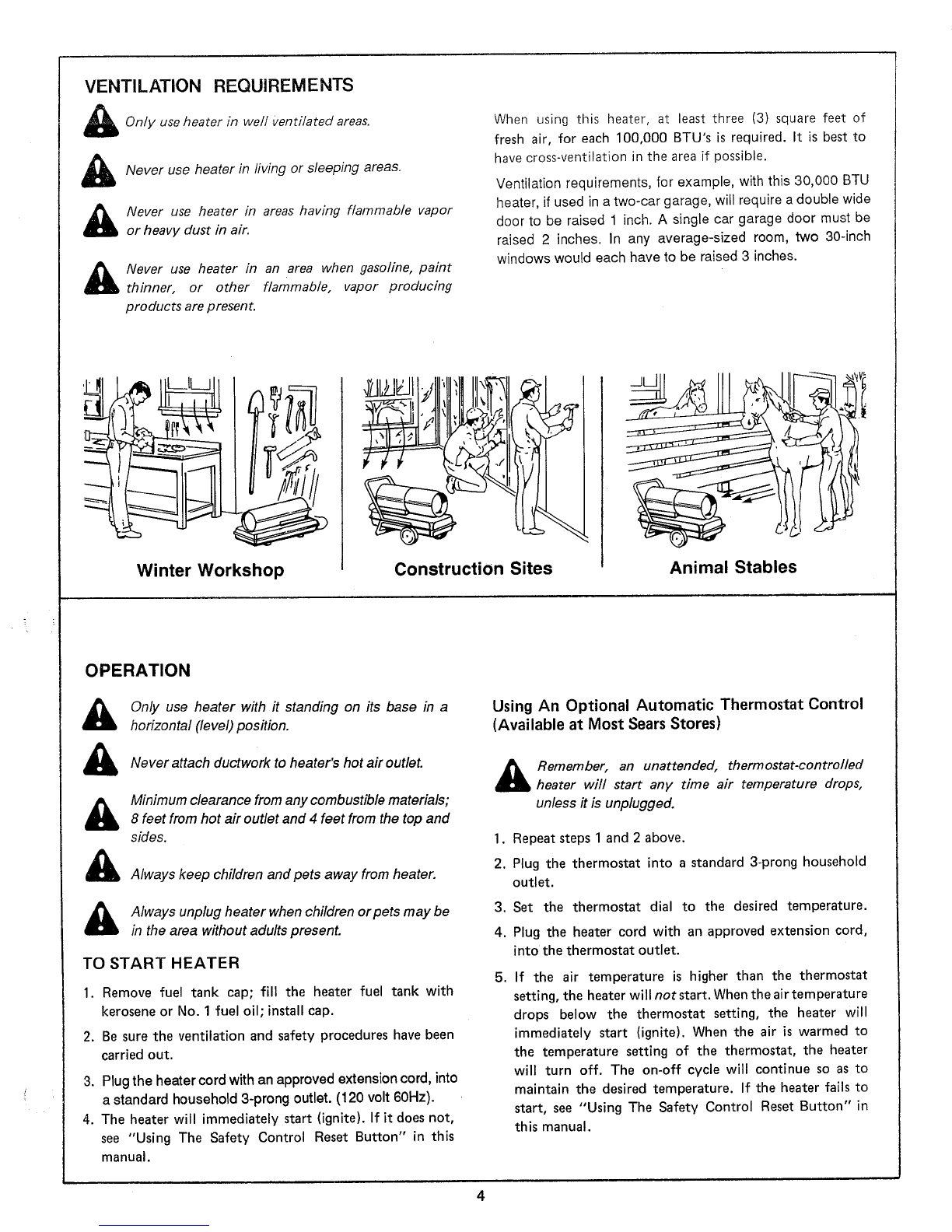
Ventilation Requirements ................. 4
Operation ............................ 4
To Start Heater ..................... 4
Using an Optional Thermostat Control ..... 4
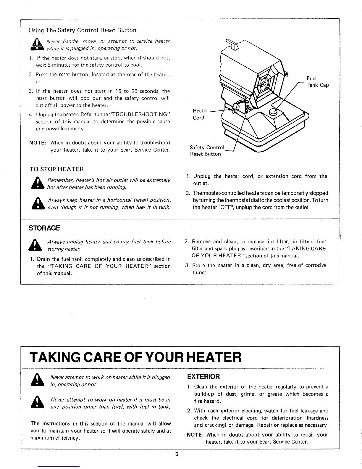
Using the Safety Control Reset Button ..... 5
To Stop Heater ..................... 5
Storage .............................. 5
TAKING CARE OF YOUR HEATER ........... 5
Exterior ............................. 5
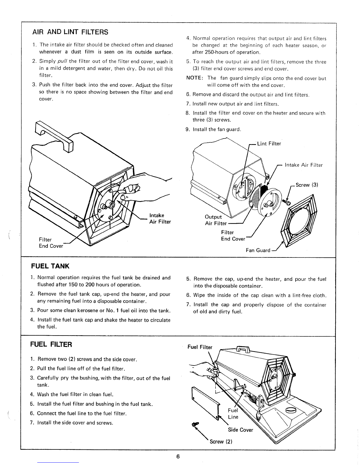
Air and Lint Filters ...................... 6
Fuel Tank ............................ 6
Fuel Filter ............................ 6
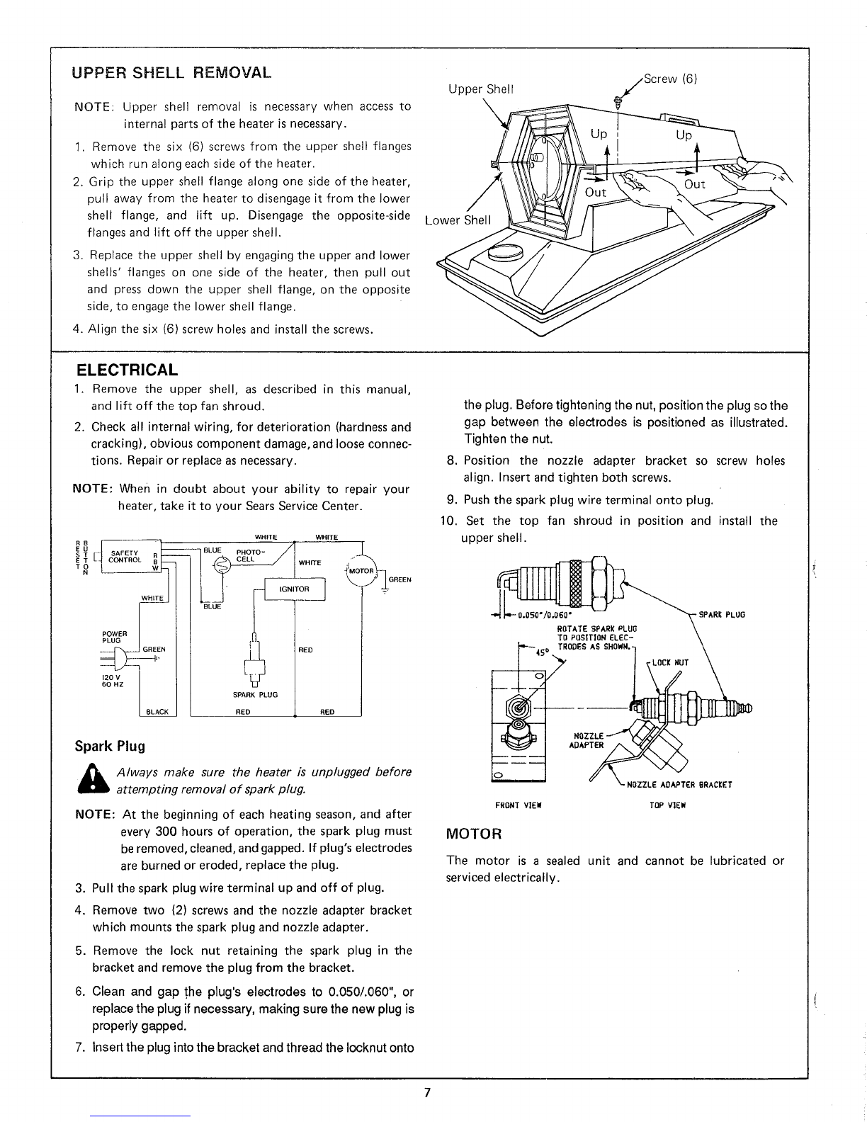
Upper Shell Removal ..................... 7
Electrical ............................ 7
Spark Plug ......................... 7
Motor ............................ 7
Cleaning the Fan ....................... 8
ADJUSTMENTS ......................... 8
Adjusting Pump Pressure .................. 8
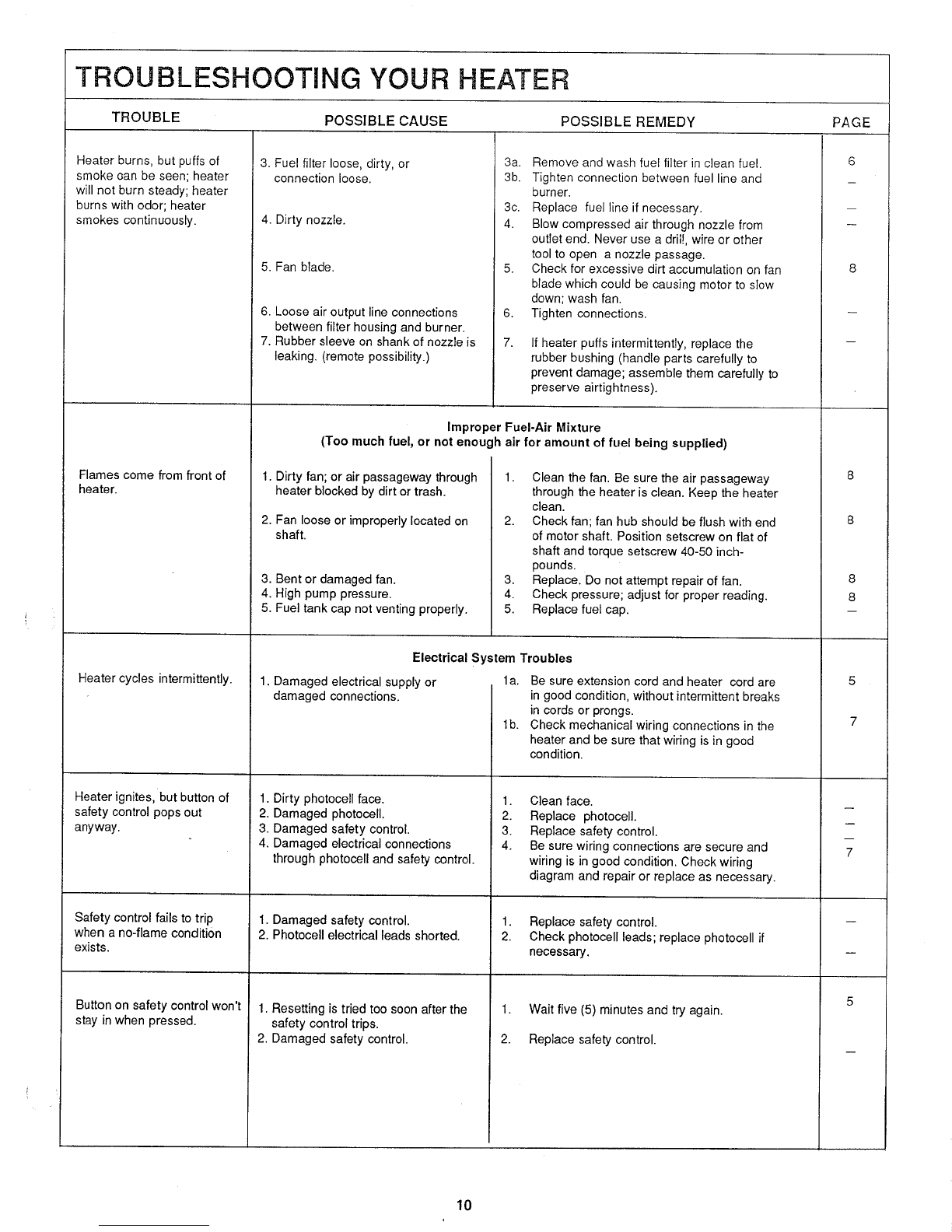
TROUBLESHOOTING YOUR HEATER ......... 9
REPAIR PARTS ......................... 11
SEARS PORTABLE HEATER ................ 14
INTRODUCTION
Read this Owner's Manual carefully and completely before
attempting to use or service this heater. Your Sears portable
heater is designed and constructed to assure a long service life
and provide maximum safety. However, improper use of any
portable heater can be dangerous to life and property. Be sure
to read and understand the following "Safety Rules". They
are also repeated in the text of the Manual and are brought
to your attention by this symbol _.
SAFETY RULES
ONLY plug heater cord into 3-wire extension cord which
plugs into standard household 3-prong outlet or properly
installed adapter.
ONLY use electrical extension cords as recommended in
this Manual.
NEVER fill heater fuel tank while heater is plugged into
outlet.
NEVER use gasoline, naphtha, paint thinner, alcohol, or
other volatile liquids asfuel.
ONLY use heater in well ventilated areas as described in
this Manual.
NEVER use heater in living or sleeping areas.
ALWAYS keep children and pets away from heater.
ALWAYS unplug heater when children or pets may be in
area without adults present.
REMEMBER, an unattended thermostat-controlled heater
will start any time air temperature drops, unless it is un-
plugged.
NEVER handle, move or attempt to service heater while it
is plugged in, operating or hot.
REMEMBER heater's hot air outlet will be extremely hot
after heater has been running.
ALWAYS keep heater in a horizontal (level) position, even
though it is not running, when fuel is in tank.
NEVER use heater in areas having flammable vapor or
heavy dust in air.
NEVER use heater in area when gasoline, paint thinner,
or other flammable, vapor-producing products are present.
ONLY use heater with it standing on its base in ahorizontal
(level) position.
NEVER attach ductwork to heater's hot air outlet.
Minimum clearance from any combustible materials: 8 feet
from hot air outlet and 4 feet from the top and sides.
ALWAYS unplug heater and empty fuel tank before storing
heater.
NEVER attempt to work on heater while it is plugged in,
while hot, or, if it must be in any position other than level,
with fuel in tank.
ALWAYS make sure heater is unplugged before attempting
to remove spark plug.
ONLY use heater in accordance with local ordinances and
code&
2

WARRANTY
ASSEMBLY
Your heater was shipped fully assembled except for the fuel tank cap and gasket to eliminate the possibility of conden-
sation in the tank. Remove the cap from the plastic bag and installonthe tank.
SAFETY COMPLIANCE
Safety requirements and model plate data comply with AMERICAN NATIONAL STANDARD INSTITUTE, INC.
Safety Requirements: ANSI A10.10-1981.
HOW TO USE YOUR HEATER
ELECTRICAL INFORMATION (The round prong on the plug is for the ground wire).
Older homes, having a 2-wire system, will require that an
adapter, with ground, be used at the outlet. These are
available at your local Sears store. They must be used in
accordancewith proper grounding instructions.
Only plug heater into 3-wire extension cord which
plugs into standard household 3-prong outlet or
properly installed adap ter.
This heater only works on standard household current
which is alternating (AC), not direct (DC), and provides
120 volts, 60 hertz. The heater uses 2.8 amperes when in use.
The standard plug, on the heater cord, is a three prong
type which mates with standard household outlets used
with standard 3-wire systems; the third wire being a ground.
Only use electrical extension cords as described
below.
Extension cord must be a 3-wire (grounded) cord of proper
wire size, as shown in the following table.
CORD LENGTH(FT). 0to75 75to125 125 to 200
MIN. WIRE SIZE (AWG). No. 18 No. 16 No. 14
FUEL SPECIFICATIONS
Never fill heater fuel tank while heater is plugged
into outlet.
Never use gasoline, naphtha, paint thinner, alcohol,
or other volatile liquids as fuel.
This heater operates on kerosene or No. 1 fuel oil. These
fuels are sold at your local fuel oil supplier or service
station.
Cold temperatures may cause fuel to thicken. Ifso, move your
heater to a warmer environment until fuel flows freely.
3

VENTILATION REQUIREMENTS
Only use heater in well Ventilated areas.
Never use heater in living or sleeping areas.
Never use heater in areas having flammable vapor
or heavy dust in air.
_Never use heater in an area when gasoline, paint
thinner, or other flammable, vapor producing
pro ducts are p resent.
When using this heater, at least three (3) square feet of
fresh air, for each 100,000 BTU's is required. It is best to
have cross-ventilation in the area if possible.
Ventilation requirements, for example, with this 30,000 BTU
heater, if used in a two-car garage, win require a double wide
door to be raised 1 inch. A single car garage door must be
raised 2 inches. In any average-sized room, two 30-inch
windows would each have to be raised 3 inches.
Winter Workshop Construction Sites Animal Stables
OPERATION
Only use heater with it standing on its base in a
horizontal (level) pos#ion.
Never attach ductwork to heater's hot air outlet.
&
&
Minimum clearance from any combustible materials;
8 feet from hot air outlet and 4 feet from the top and
sides.
Always keep children and pets away from heater.
Always unplug heater when children orpets may be
in the area without adults present.
TO START HEATER
1. Remove fuel tank cap; fill the heater fuel tank with
kerosene or No. 1 fuel oil; install cap.
2. Be sure the ventilation and safety procedures have been
carried out.
3. Plug the heatercord with an approved extension cord, into
a standard household 3-prong outlet. (120 volt 60Hz).
4. The heater will immediately start (ignite). If it does not,
see "Using The Safety Control Reset Button" in this
manual.
Using An Optional Automatic Thermostat Control
(Available at Most Sears Stores)
_emember, an unattended, thermostat-controlled
heater will start any time air temperature drops,
unless it is unplugged.
1. Repeat steps 1 and 2 above.
2. Plug the thermostat into a standard 3-prong household
outlet.
3.
4.
5o
Set the thermostat dial to the desired temperature.
Plug the heater cord with an approved extension cord,
into the thermostat outlet.
If the air temperature is higher than the thermostat
setting, the heater will not start. When the air temperature
drops below the thermostat setting, the heater will
immediately start (ignite). When the air is warmed to
the temperature setting of the thermostat, the heater
will turn off. The on-off cycle will continue so as to
maintain the desired temperature. If the heater fails to
start, see "Using The Safety Control Reset Button" in
this manual.
4

UsingTheSafetyControlResetButton
_ever handle, move, or attempt to service heater
while it is plugged in, operating or hot.
1. If the heater does not start, or stops when it should not,
wait 5-minutes for the safety control to cool.
2. Press the reset button, located at the rear of the heater,
in.
3. If the heater does not start in 15 to 25 seconds, the
reset button will pop out and the safety control will
cut off all power to the heater.
4. Unplug the heater. Refertothe"TROUBLESHOOTING"
section of this manual to determine the possible cause
and possible remedy.
NOTE: When in doubt about your ability to troubleshoot
your heater, take it to your Sears Service Center.
Heater
Cord
Safety Control
Reset Button
Fuel
Tank Cap
TO STOP HEATER
Remember, heater's hot air outlet will be extremely
hot after heater has been running.
Always keep heater in a horizontal (level) position,
even though it is not running, when fuel is in tank.
1. Unplug the heater cord, or extension cord from the
outlet.
2. Thermostat-controlled heaters can be temporarily stopped
byturning the thermostat dial to the coolest position. To turn
the heater "OFF", unplug the cord from the outlet.
STORAGE
Always unplug heater and empty fuel tank before
storing heater.
1. Drain the fuel tank completely and clean as described in
the "TAKING CARE OF YOUR HEATER" section
of this manual.
2. Remove and clean, or replace lint filter, air filters, fuel
filter and spark plug as described in the "TAKING CARE
OF YOUR HEATER" section of this manual.
3. Store the heater in a clean, dry area, free of corrosive
fumes.
TAKING CARE OF YOUR HEATER
&
&
Never attempt to work on heater while it is plugged
in, operating or hot.
Never attempt to work on heater if it must be in
any position other than level, with fuel in tank.
The instructions in this section of the manual will allow
you to maintain your heater so it will operate safely and at
maximum efficiency.
EXTERIOR
1. Clean the exterior of the heater regularly to prevent a
build-up of dust, grime, or grease which becomes a
fire hazard.
2. With each exterior cleaning, watch for fuel leakage and
check the electrical cord for deterioration (hardness
and cracking) or damage. Repair or replace as necessary.
NOTE: When in doubt about your ability to repair your
heater, take it to your Sears Service Center.

AIR AND LINT FILTERS
1. The intake air filter should be checked often and cleaned
whenever a dust film is seen on its outside surface.
2. Simply puff the filter out of the filter end cover, wash it
in a mild detergent and water, then dry. Do not oil this
filter.
3. Push the filter back into the end cover. Adjust the filter
so there is no space showing between the filter and end
cover,
4. Normal operation requires that output air and lint filters
be changed at the beginning of each heater season, or
after 250-hours of operation.
5. To reach the output air and lint filters, remove the three
(3) filter end cover screws and end cover.
NOTE: The fan guard simply slips onto the end cover but
will come off with the end cover.
6. Remove and discard the output air and lint filters.
7. Install new output air and lint filters.
8. Install the filter end cover on the heater and secure with
three (3) screws.
9. Install the fan guard.
Filter
Intake Air Filter
(3)
Filter
End Cover
Intake
Air Filter Output
Air Filter
Filter
End Cover
Fan Guard
FUEL TANK
1. Normal operation requires the fuel tank be drained and
flushed after 150 to 200 hours of operation.
2. Remove the fuel tank cap, up-end the heater, and pour
any remaining fuel into a disposable container.
3. Pour some clean kerosene or No. 1 fuel oil into the tank.
4. Install the fuel tank cap and shake the heater to circulate
the fuel.
5. Remove the cap, up-end the heater, and pour the fuel
into the disposable container.
6. Wipe the inside of the cap clean with a lint-free cloth.
7. Install the cap and properly dispose of the container
of old and dirty fuel.
FUEL FILTER
1. Remove two (2) screws and the side cover.
2. Pull the fuel line off of the fuel filter.
3. Carefully pry the bushing, with the filter, out of the fuel
tank.
4. Wash the fuel filter in clean fuel.
5. Install the fuel filter and bushing in the fuel tank.
6. Connect the fuel line to the fuel filter.
7. Install the side cover and screws.
Fuel Filter
[2
\ rew:eO°ver
6

UPPER SHELL REMOVAL
NOTE: Upper shell removal is necessary when access to
internal parts of the heater is necessary.
1. Remove the six (6) screws from the upper shell flanges
which run along each side of the heater.
2. Grip the upper shell flange along one side of the heater,
pull away from the heater to disengage it from the lower
shell flange, and lift up. Disengage the opposite-side
flanges and lift off the upper shell.
3. Replace the upper shell by engaging the upper and lower
shells' flanges on one side of the heater, then pull out
and press down the upper shell flange, on the opposite
side, to engage the lower shell flange.
4. Align the six (6) screw holes and install the screws.
Upper Shell
Lower Shell
/zScrew (6)
ELECTRICAL
1. Remove the upper shell, as described in this manual,
and lift off the top fan shroud.
2. Check all internal wiring, for deterioration (hardness and
cracking), obviouscomponent damage, and looseconnec-
tions. Repair or replace as necessary.
NOTE: When in doubt about your ability to repair your
heater, take it to your Sears Service Center.
EU
S T SAFETY
ETCONTROL
WHITE
POWER
6OI20PLUGHZVGREb_ EN
WHITE WHITE
BLUE PHOTO -
CELL WHITE
SPARK PLUG
RED RED
Spark Plug
Always make sure the heater is unplugged before
attempting removal of spark plug.
NOTE: At the beginning of each heating season, and after
every 300 hours of operation, the spark plug must
be removed, cleaned, and gapped. If plug's electrodes
are burned or eroded, replace the plug.
3. Pull the spark plug wire terminal up and off of plug.
4. Remove two (2) screws and the nozzle adapter bracket
which mounts the spark plug and nozzle adapter.
5. Remove the lock nut retaining the spark plug in the
bracket and remove the plug from the bracket.
6. Clean and gap the plug's electrodes to 0.050/.060", or
replace the plug if necessary, making sure the new plug is
properly gapped.
7. Insert the plug into the bracket and thread the Iocknut onto
the plug. Before tightening the nut, position the plug so the
gap between the electrodes is positioned as illustrated.
Tighten the nut.
8. Position the nozzle adapter bracket so screw holes
align. Insert and tighten both screws.
9. Push the spark plug wire terminal onto plug.
10. Set the top fan shroud in position and install the
upper shell.
FRONT VIEW
ROTATE SPARK PLUG
TO POSITION ELEC-
PLUG
ADAPTER
NOZZLE ADAPTER BRACKET
TOP VIEW
MOTOR
The motor is a sealed unit and cannot be lubricated or
serviced electrically.

CLEANING THE FAN
1. Remove the upper shell, as described in this manual, and
lift off the top fan shroud.
2. Wash the mounted fan with a damp cloth then dry carefully
so as not to bend the blades. Iffan is very dirty, loosen the
fan'setscrew and slip the fan off of the motor shaft. Wash the
fan in detergent and water, and then dry the fan carefully so
as not to bend the blades.
3. Slip the fan onto the motor shaft. Fan hub should be flush
with end of the motor shaft. Place the setscrew on flat of
shaft and torque setscrew 40-50 inch-pounds.
4. Install the upper shell as described in this manual.
Fan
Set Screw
ADJUSTMENTS
1. Remove the plug from the filter end cover and thread
the accessory pressure gauge into the hole.
2. Start the heater and allow it to burn.
3. The pressure gauge should read 3.0 PSI. If not, turn the
adjusting screw in (clockwise) to increase the pressure or
out (counter clockwise) until the gauge reads 3.0 PSI.
4. Unplug the heater.
5. Remove the gauge and replace the plug.
Filter
Pipe Plug m End Cover
Hole
Accessory
Pressure Gauge---_
Clockwise
Counter
Clockwise Adjusting
Screw

TROUBLESHOOTING YOUR HEATER
TROUBLE POSSIBLE CAUSE POSSIBLE REMEDY
1. No power or low voltage at heater.
2. Safety control not functioning.
3. Motor not functioning.
4. Thermostat control (if used) not
functioning.
Electrical Troubles
la. Press reset button on safety control.
lb. Be sure outlet is delivering adequate voltage.
lc. Check condition of heater and extension
cord. Repair or replace.
ld. Be sure extension cord complies with
requirements as stated in this manual.
2. Replace safety control.
3. Check motor. Replace if necessary.
4. Replace thermostat control.
Mechanical Troubles
Heater is plugged in but
motor does not start;
thermostat (if used) is set to
call for heat but motor does
not start.
Heater will not ignite, but
motor runs for a short time.
1. Fan obstructed by mechanical
damage or dirt.
2. Motor pump binding.
PAGE
5
3
5
3
la. Check for bent sheetmetal shells or shrouds; replace _
if necessary.
lb. Check for damaged fan; clean or replace if 8
necessary.
lc. Check for damaged motor mounting bracket;
replace if necessary.
2. Check pump for easy rotation; clean or
replace if necessary.
Fuel System Troubles
1. Fuel tank empty; water in fuel; wrong la. Fill tank if empty.
fuel. lb. Check for water in tank: clean tank and fuel
2. Fuel filter clogged.
3. Nozzle plugged or damaged.
3
6
4. Very low temperature may cause fuel
to thicken and not flow.
5. Dirty air filters.
6. Air leak at fuel filter.
filter if water is found (water in the tank will
form globules in the bottom which can be
seen).
lc. Add fresh, clean fuel to tank. 6
2. Remove and wash in clean fuel. 6
Reinstall.
3a. Clean by blowing compressed air through
nozzle from outlet end.
3b. Replace nozzle if cleaning does not solve the
problem.
4. Move heater into a warmer environment until 3
fuel flows freely.
5. Clean air filters. 6
6. Check fuel line to fuel filter fit and fuel line to
nozzle adapter for air leaks. Seal if needed.
A Ignition Troubles
WARNING: DISCONNECT HEATER CORD!
1. Spark plug wire disconnected from
plug.
2. Damaged spark plug. (Wrong gap,
plug wet with fuel or electrodes
carboned, or plug damaged).
A2d. Replace a damaged spark plug.
WARNING: HIGH VOLTAGE
1. Install wire on plug. 7
2a. Gap between electrodes should be per.specification 7
chart. Adjust electrode gap. 7
2b. Dry plug.
2c. Inspect plug for worn or eroded electrodes, replace if 7
necessary. 7
3. Damaged electronic ignitor.
Heater burns, but puffs of
smoke can be seen; heater
will not burn steady; heater
burns with odor; heater
smokes continuously.
3a. Unplug heater cord and removethefan.
3b. Disconnect wirefrom spark plug and check for
spark;replaceifnosparkcan be obtained.
Improper Fuel-Air Mixture (Not enough fuel)
la. Check fuel tank. If globules of water are
seen in the bottom, drain and flush the tank
and filter with clean fuel.
lb. Fill tank with fresh, clean fuel.
2. Remove and clean the air filters. Be sure air
intake is not blocked.
1. Heater running out of fuel; water
condensationin fuel tank;wrong fuel.
2. Dirty air filters causing reduced air
flow through nozzle, resulting in low
fuel flow.
3
6

TROUBLESHOOTING YOUR HEATER
TROUBLE POSSIBLE CAUSE POSSIBLE REMEDY PAGE
Heater burns, but puffs of
smoke can be seen; heater
will not burn steady; heater
burns with odor; heater
smokes continuously.
3. Fuel filter loose, dirty, or
connection loose.
Flames come from front of
heater.
4. Dirty nozzle.
Heater cycles intermittently.
5. Fan blade.
6. Loose air output line connections
between filter housing and burner.
7. Rubber sleeve on shank of nozzle is
leaking. (remote possibility.)
3a. Remove and wash fuel filter in clean fuel.
3b. Tighten connection between fuel line and
burner.
3c. Replace fuel tine if necessary.
4. Blow compressed air through nozzle from
outlet end. Never use a dril!, wire or other
tool to open a nozzle passage.
5. Check for excessive dirt accumulation on fan
blade which could be causing motor to slow
down; wash fan.
6. Tighten connections.
7. If heater puffs intermittently, replace the
rubber bushing (handle parts carefully to
prevent damage; assemble them carefully to
preserve airtightness).
Heater ignites, but button of
safety control pops out
anyway.
Safety control fails to trip
when a no-flame condition
exists.
Button on safety control won't
stay in when pressed.
Improper Fuel-Air Mixture
(Too much fuel, or not enough air for amount of fuel being supplied)
• Dirty fan; or air passageway through
heater blocked by dirt or trash.
2. Fan loose or improperly located on
shaft.
3. Bent or damaged fan.
4. High pump pressure.
5. Fuel tank cap not venting properly.
1. Clean the fan. Be sure the air passageway
through the heater is clean• Keep the heater
clean.
2. Check fan; fan hub should be flush with end
of motor shaft. Position setscrew on flat of
shaft and torque setscrew 40-50 inch-
pounds.
3, Replace. Do not attempt repair of fan.
4. Check pressure; adjust for proper reading.
5. Replace fuel cap.
Electrical System Troubles
1. Damaged electrical supply or
damaged connections•
1. Dirty photocell face.
2. Damaged photocell,
3. Damaged safety control.
4, Damaged electrical connections
throughphotocell and safety control.
1. Damaged safety control.
2. Photocell electrical leads shorted•
1. Resetting is tried too soon after the
safety control trips•
2. Damaged safety control.
la. Be sure extension cord and heater cord are
in good condition, without intermittent breaks
in cords or prongs.
lb. Check mechanical wiring connections in the
heater and be sure that wiring is in good
condition.
1. Clean face.
2. Replace photocell.
3. Replace safety control.
4. Be sure wiring connections are secure and
wiring is in good condition. Check wiring
diagram and repair or replace as necessary.
1. Replace safety control.
2. Check photocell leads; replace photocell if
necessary.
1. Wait five (5) minutes and try again•
2. Replace safety control.
6
m
8
8
5
7
m
7
10

REPAIR PARTS
SEARS PORTABLE H EATE R
MODEL 583.356001
@
11
21
=oK1
23 I
\
38
37
28
25 47
29
11

REPAIR PARTS
SEARS PORTABLE HEATER
MODEL 583.356001
KEY
NO. PART NUMBER PART DESCRIPTION
1
2
3
4
5
6
7
8
9
10
11
12
13
14
15
16
17
18
19
20
21
22
23
24
25
26
27
28
29
30
31
32
33
34
35
36
37
38
39
4O
41
42
43
44
45
46
47
** Available at
079437-01
M11084-29
079424-01 BF
M50834
M29678
M50785-02
M29824
M29681
097124-01
M29835
079980-01
M16660
M16656-4
M50833
M51061-01
NTC-4C
M29652-04
M29652-05
079423-01BF
M11271-8
M10990-3
M50876-04
079870-01
097702-01
M50671-01
097137-02
M11084-27
M11084-26
M11143-1
M10813-86
M50837
M25907
M30865-02
M50104-02
M15823-37
079552-01BH
M10908-2
M50631
079900-01
M15823-27
'liar
097098-01
your local hardware store.
Handle
Screw (10-14 x 9/16, 2 Required)
Upper Shell
Fan Shroud (Top)
Fan w/Setscrew
Motor and Pump Assembly (See Page 13)
Combustion Chamber
Burner Head Assembly (See Keys 9-13)
Special Lock Nut (14MM)
Siphon Nozzle
Nozzle Adapter Bracket
Spark Plug
Nozzle Adapter
Photocell Bracket
Photocell
Fan Shroud (Bottom)
Motor Mounting Bracket
Hex Nut (1/4, 2 Required)
Airline (Rubber Tubing)
Fuel Line (Rubber Tubing)
Lower Shell
Clip Nut (6 Required)
Bushing
Fuel Filter
Electronic Ignitor
Fuel Tank Cap
Safety Control w/Reset Button and Hex Nut
Fuel Tank
Screw (10-16 x 1/2, 2 Required)
Screw (10-16 x 3/8, 10 Required)
Strain Relief Bushing
Heater Cord
Fan Guard
Snap Bushing
Open/Closed Bushing
Shorty Bushing
Grounding Screw
Side Cover
Screw (6-32 x 3/8, 2 Required)
Rubber Bumper (2 Required)
Wire Nut (Red, for 3-#18 AWG wires))
Wire Nut (White, for 5-#18 AWG wires)
Wire Nut (Blue, for 2-#18 AWG wires)
Ignitor Cable Assembly
Screw (10-16 x 1/2, 6 Required)
Primary Wire (White)
Primary Wire (Red)
Owner's Manual (F642-3886)
12

REPAIR PARTS
MOTOR AND PUMP ASSEMBLY
MODEL 583.356001
KEY
NO.
1
2
3
4
5
6
7
8
9
10
11
12
13
14
15
16
17
18
PART NUMBER
097073-01
079975-01
M22009
M22456-1
M29608
M29632
M29633
M29609
M12461-31
M27694
M10993-1
M22997
M8940
M29612-01
M12461-31
M50016
M8643
FHPF3-2C
PART DESCRIPTION
Motor
Pump Body
Rotor Insert
Pump Rotor
Pump EndCover
LintFilter
IntakeAir Filter
Filter End Cover
Screw (10-32 x 1,3 Required)
Adjusting Screw
Pressure ReliefSpring
Pipe Plug
Steel Ball(1/4 inch)
OutputAirFilter
Screw (10-32 x 1,6 Required)
90°Elbow
Blade (4 Required)
Screw (10-32 x 1/4, 2 Required)
13

OWNER'S
MANUAL
SERVICE
MODEL NO.
583.356001
HOW TO ORDER
REPAIR PARTS
PARTS
SEARS PORTABLE HEATER
MODEL 583.356001
PARTS AVAILABLE-NOT SHOWN
079428-01 TradenameDecal
097098-01 Owner'sManual
OPTIONAL ACCESSORIES
583.409960 Pressure Gauge
583.401050 Wheel and Handle Kit
SEARS
PORTABLE HEATER
Should a need for repair parts or service occur, contact a Sears Service
Center. Be sure to provide all pertinent facts when you call or visit.
The model and serial number of your portable heater will be found on a
decal located on top of the heater, towards the rear.
WHEN ORDERING REPAIR PARTS,
ALWAYS GIVE THE FOLLOWING INFORMATION:
1. Part Number
2. Model Number
3. Part Description
4. Name or Merchandise
If the parts you needare not stocked locally, your order will be electronical ly
transmitted to a Sears Repair Parts Distribution Center for "expedited
handling".
Sears, Roebuck and Co., Chicago, IL 60684
097098-01
F642-3886 PRINTED IN U.S.A. 7A
Table of contents
Popular Electric Heater manuals by other brands

Lucci CONNECT
Lucci CONNECT Thermastrip manual

Harvia
Harvia TRT70 Instructions for installation and use

Kingfisher
Kingfisher GHFSWC25BUK manual

MrHeater
MrHeater MHBE150FAT Operating instructions and owner's manual

Chromalox
Chromalox S-RAD-2 Installation and operating instructions

Cadet
Cadet Portable Baseboard owner's manual

Bradford White
Bradford White Convection Heater Installation and operating instruction manual

Chemin'Arte
Chemin'Arte Lounge instruction manual

DeLonghi
DeLonghi ELECTRIC CONVECTOR HEATER Instructions for use

Roberts Gorden
Roberts Gorden VANTAGE NP CTHN-125 Installation & operation

Lasko
Lasko 6251 operating manual

Master
Master B15 EPB owner's manual