4HSF (M) 600W 042315
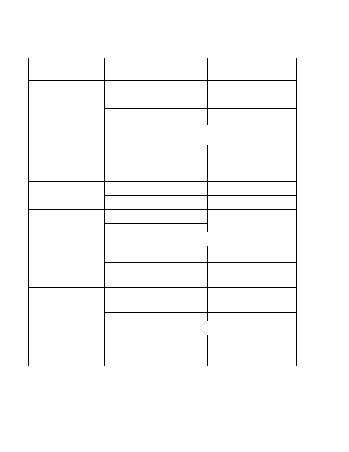
TABLE 3. POWER SUPPLY RATINGS AND SPECIFICATIONS
CHARACTERISTIC SPECIFICATION CONDITION/NOTES
Input Voltage Nominal: 100-120V a-c, 200-240V a-c
Range: 85-264V a-c(1), 110-370V d-c 0 to 100% load, -10 to 40°C
Input Source Frequency Nominal: 50-60 Hz
Range: 47-440 Hz 0 to 100% load, -10 to 40°C
At 440 Hz leakage current exceeds
UL/VDE safety spec. limit.
Input Current: (Maximum Load At
25°C with Nominal Output Voltage) 8.4A rms max. 100 - 120V a-c
4.2A rms max. 200 - 240V a-c
Switching Frequency 140KHz typ. Forward Converter
Input Protection A limiting resistor in series with a resistor fuse (and thyristor circuit) reduces start-up surge.
The internal power supply is protected against shorts by an input fuse. Fuse value 15.0A at
250 Volts
Input Surge cold start, interval > 30
sec (First surge only, not including
current flow into EMI filter)
15A typ., 30A max. first surge 100 - 120V ac
30A typ., 60 max. first surge 200- 240 V ac
Leakage Current: 0.45mA typ., 0.75mA max. 120V a-c, 60Hz per IEC 950 and UL1950
0.60mA typ., 0.75mA max. 240V a-c, 60Hz per IEC 950 and UL1950
Power Factor 0.99 typical 100V a-c, max load, nominal output,
per EN 61000-3-2
0.95 typical 200V a-c, max load, nominal output
per EN 61000-3-2
Transient Recovery excursion
characteristic ±4% maximum 50% to 100% load,
transient time >50sec
recovery time 1 ms maximum
Stabilization NOTE: Refer to Table 2, ripple and noise and Note (8) for minimum output voltage required to
meet stabilization specifications.
Source Effect (min - max) ±0.1% Typical, ±0.2% Maximum 85 to 132V a-c, 170 to 264V a-c
Load Effect ±0.3% Typical, ±0.6% Maximum (2) 0%-100% load change
Temperature Effect ±0.5% Typical, ±1.0% Maximum –10° to 40°C
Combined Effect ±0.9% Typical, ±1.8% Maximum Source, Load and Temperature
Time Effect 0.2% Typical, 0.5% Maximum 1/2 to 8 hours at 25°C
Start-up Time 280 msec Typical, 350 msec Maximum 100V a-c
100 msec Typical, 150 msec Maximum 240V a-c
Output Hold-up Time 30 msec Typical, 20 msec Minimum. 100V a-c
40 msec Typical, 20 msec Minimum. 240V a-c
Overvoltage Protection When the Power Supply goes into an overvoltage condition, the output is cut OFF. See PAR.
3.7.1.
Remote Control ON/OFF: ±RC pins control on/off as follows:
“High”, 2.4V to 24V (or open), unit OFF- Fan Off;
“Low”, 0.0V to 0.4V (or closed), unit ON.
Source current: 1.6mA maximum at low level
Sink current: 1.0 mA maximum at high level.
Must be enabled by DIP switch positions 3
and 4 (see PAR. 3.5).
(1) For input voltage between 85 to 95V a-c maximum operating temperature is 35°C.
(2) MZ Models: ±0.3% Typical, ±2% Maximum (default). When VDC/ALARM ON powered from internal reference voltage: ±0.6%
Maximum, ±0.3% Typical (see PAR 3.4.3).