KEPCO BOP 2X-DE Series User manual

©2019, KEPCO, INC 1
Data subject to change without notice 228-1921
KEPCO, INC. 131-38 SANFORD AVENUE FLUSHING, NY. 11355 U.S.A. TEL (718) 461-7000FAX (718) 767-1102
www.kepcopower.com email: hq@kepcopower.com
QUICK START GUIDE
KEPCO An ISO 9001 Company.
BOP
2X-DE SERIES
BIPOLAR 2X-DE SERIES
DUAL CHANNEL OPERATIONAL POWER SUPPLY
I — INTRODUCTION
1.1. SCOPE OF MANUAL. This Quick Start Guide
covers simple installation and local operation of the Kepco
BOP 2X-DE Series Dual Channel Bipolar Operational
Power Supply, hereafter referred to as BOP 2X-DE. Com-
plete specifications, features and instructions are found in
the full BOP 2X-DE Series Operator Manual that can be
downloaded free from the Kepco web site at:
www.kepcopower.com/support/opmanls.htm#bop-op
1.2. DESCRIPTION.
Kepco's Series BOP 2X-DE dual-channel BOP models are
200W and 400W power supplies. Each channel is a sepa-
rate power supply, completely isolated, independent and
functionally identical. The 200W units have two 100W
channels and the 400W units have two 200W channels.
The channels are completely isolated, but share two digital
front panel meters (without affecting isolation) which dis-
play d-c output voltage and current for the channel selected
by the front panel Channel select switch. A single power
cord powers both channels; separate on-off circuit breakers
turn each channel on/off separately.
Each BOP 2X-DE channel is a linear stabilizer with two
bipolar control loops (voltage or current mode), selectable
and individually controllable by remote signals applied to
the PC 15 programming connector at the rear panel. These
two principal control loops are each protected by bipolar
limit circuits. The positive and negative current or voltage
limit points can be remotely programmed simultaneously or
Individually. Automatic crossover between each principal
control loop and the limit loops is provided. Only one princi-
ple loop (voltage or current) can control the output at any
one time.
Each channel can operate automatically in all four voltage-
current quadrants; it can act as either a source (output volt-
age is the same polarity as output current) or a sink (output
voltage is opposite the polarity of output current). An exam-
ple is shown in Figure 1 where the BOP channel is pro-
grammed to deliver a sine wave output and the load
produces a phase shift between the output voltage and cur-
rent. See BOP 2X-DE Series Operator Manual (PAR. 1.1)
for limits on long-term operation in sink mode.
Remote On-Off Feature. A remote on-off feature provides
Isolated remote on-off control of the output; an associated
flag signal is configured at the PC 15 programming connec-
tor.
Units are shipped for 115V a-c operation (105V to 125V
a-c), 57 to 63Hz. For operation at 104V a-c, 208V a-c or
230V a-c refer to the full Operator Manual (PAR 1.1).
LAN OPERATION. Each channel of the BOP 2X-DE
includes a LAN interface that accepts digital data bus infor-
mation from a computer and converts it to an analog signal
which, in turn, controls the channel output.
FIGURE 1. SINK OPERATION PRODUCED BY LOAD
PHASE SHIFT
1.3. OPTIONS. Models optimized to operate in current
mode with large inductive loads are identified by suffix L.
Models optimized to operate in voltage mode with large
capacitive loads are identified by suffix C.
1.4. EQUIPMENT SUPPLIED.
• Two PC 15 programming connectors. One PC 15
programming connectors MUST be installed at the
rear panel of each channel to enable operation.
• 115V a-c Line Cord NEMA 5-15P-C13
1.5. ACCESSORIES (NOT SUPPLIED)
• Slides

2228-1921 022720
KEPCO, INC. 131-38 SANFORD AVENUE FLUSHING, NY. 11355 U.S.A. TEL (718) 461-7000FAX (718) 767-1102
http://www.kepcopower.com email: hq@kepcopower.com
II — SAFETY.
Exercise care in making all connections to and from the
BOP terminals. WARNINGS
1. Remove a-c power from the BOP 2X-DE before mak-
ing any connections.
2. Wires and/or cables, connected from the BOP termi-
nals to external components or programming devices
must be properly insulated and securely terminated on
both sides to make accidental touch impossible.
3. The BOP 2X-DE chassis and cover must be safety-
grounded to a reliable a-c source ground. A safety-
ground may be established by using a grounded a-c
power outlet or, if the latter is not available, by means
of a separate wire, from the provided GND terminal of
the rear panel terminal block to a reliable a-c source
ground point.
4. THE COM OUTPUT TERMINALS OF THE BOP 2X-
DE channel MAY EITHER FLOAT OR BE
GROUNDED. Leave the output terminal floating when
an externally grounded device is used at either the pro-
gramming input or the output, or for a grounded load.
For noise reduction ground a single return terminal on
either the programming device, the BOP or the load
configuration. See “D-C Signal Ground.” on page 3 for
the maximum allowable floating voltage for the output
terminals.
III — INSTALLATION
3.1. UNPACKING. The power supply has been thor-
oughly inspected and tested prior to packing and is ready
for operation. After careful unpacking, inspect for shipping
damage before attempting to operate. Perform the Prelim-
inary Checkout (PAR. 3.2). If any indication of damage is
found, file an immediate claim with the responsible trans-
port service
3.2. PRELIMINARY CHECKOUT. A simple oper-
ating check after unpacking and before permanent instal-
lation, is advisable to ascertain whether the BOP 2X-DE
has suffered damage in shipment.
1. Install PC 15 programming connectors (supplied) for
each channel under test at the rear panel. This is
required for proper operation of each channel.
2. Set the CHANNEL 1 - CHANNEL 2 selector switch to
CHANNEL 1.
3. Refer to Safety instructions (see Section II) and con-
nect channel to 115V a-c source; see Operator Manual
(PAR 1.1) for different source voltage.
4. Connect the channel to a computer as specified in
“CONNECT BOP2X-DE CHANNEL TO NETWORK.”
on page 4.
5. Set the a-c POWER switch for channel under test to
ON. CAUTION: DO NOT repeatedly toggle the
POWER on/off switch as this may cause unit to
fault. If actuator does not lock when released, wait a
few seconds before trying again. The circuit breaker is
“trip-free;” if overload exists, contacts cannot be held
closed by actuator.
6. Using a thin tool (e.g., the end of a paper clip), press
then release the LAN Reset pushbutton switch of the
channel under test (see Figure 8). The LAN indicator
will blink briefly, then remain on.
7. Locate the BOP/BIT using the PS Find utility as speci-
fied in “FINDING KEPCO POWER SUPPLIES ON
THE LAN.” on page 4
8. From the PS Find screen (Figure 5) click Launch
Webpage to view the Instrument Home page (Figure
2). Verify the model is correct, matching the voltage
and current of the BOP channel in use. The serial no.
of channel 1 ends in A, channel 2 ends in B. To verify
the correct unit/channel has been selected, click ID
INSTRUMENT at the left of the Instrument Home
page. This causes the associated LAN indicator (see
Figure 8) on the BOP 2X-DE rear panel to blink.
FIGURE 2. INSTRUMENT HOME PAGE
9. Click on the OPERATE INSTRUMENT tab of the home
page. Leave password blank and click Submit to
access the Operate Instrument page (see Figure 3).

KEPCO, INC. 131-38 SANFORD AVENUE FLUSHING, NY. 11355 U.S.A. TEL (718) 461-7000FAX (718) 767-1102
http://www.kepcopower.com email: hq@kepcopower.com
022720 228-1921 3
10.If necessary, click on the MODE button at the upper
right side of the Operate Instrument page until the indi-
cator above the MODE button reads VOLTAGE.
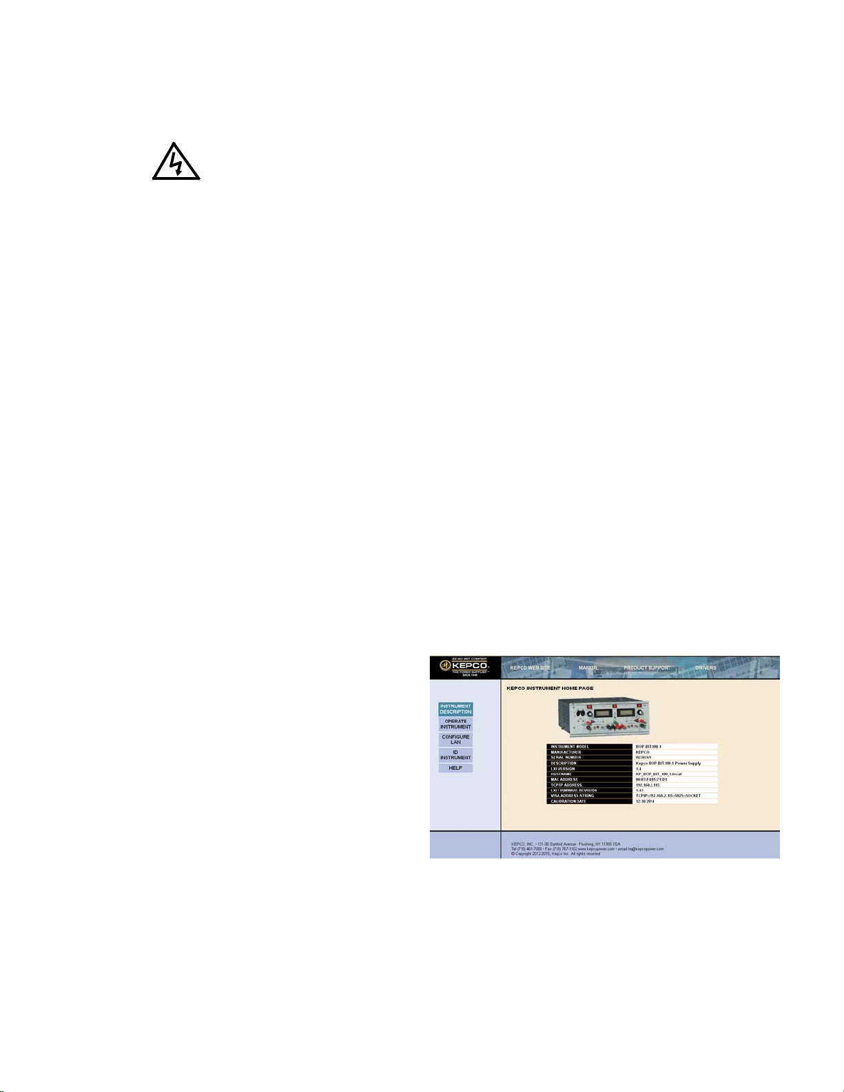
11.Set the unit to output +8.1V by entering +8.1 in the
VOLTAGE field, then click SET. Verify the output of the
BOP changes and the voltage indication is +8.1V on
both the web page and the BOP front panel.
FIGURE 3. OPERATE INSTRUMENT PAGE
12.Repeat steps 1 through 11 for channel 2. At step 2 set
selector switch to CHANNEL 2
13.Set the a-c POWER switch for channels 1 and 2 to OFF.
3.3. INSTALLING THE POWER SUPPLY. These
models are shipped with fixed angle brackets and chassis
slide support bars installed and are ready for mounting in a
19-inch rack.
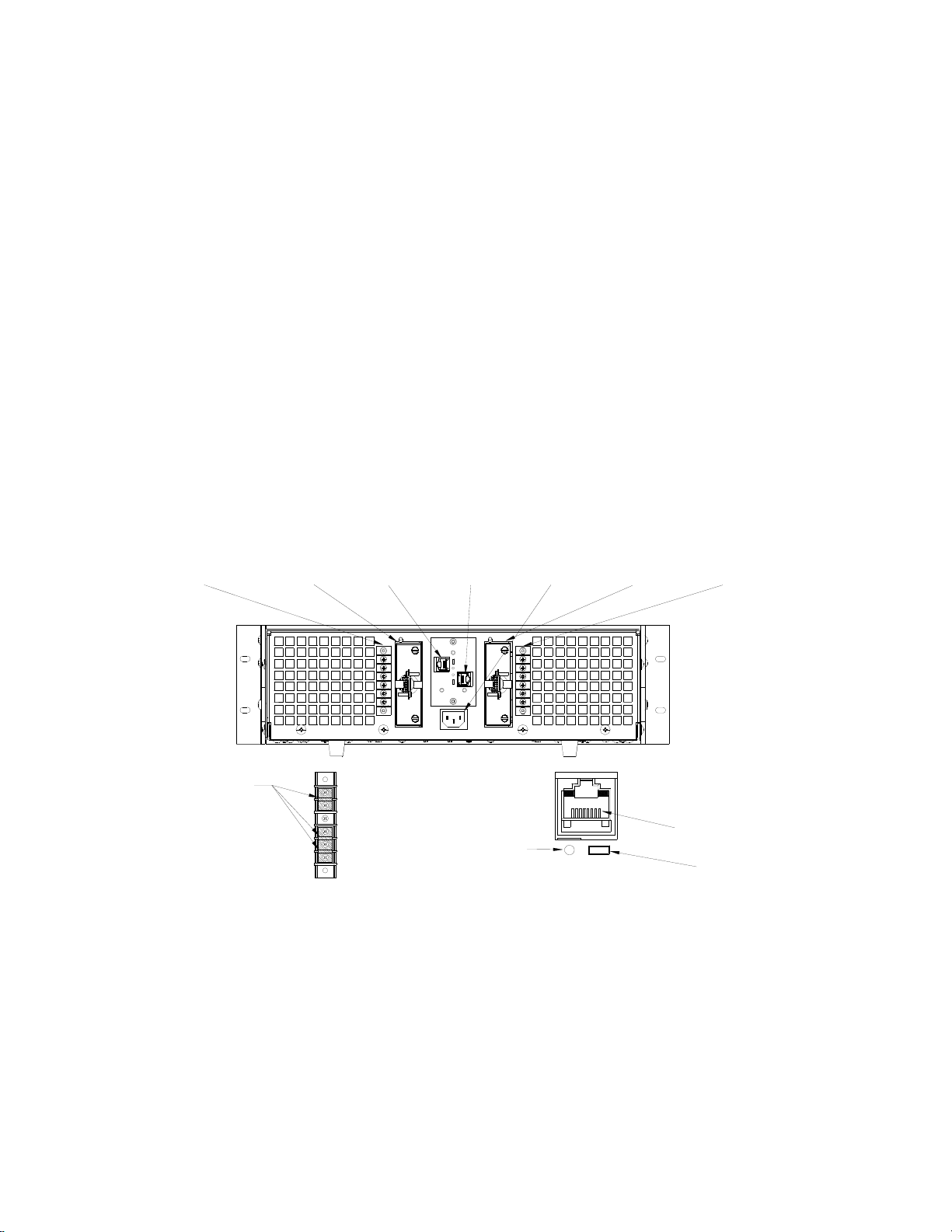
3.4. CONNECTIONS. Connections to the load are
made using the rear panel terminations.
LOAD CONNECTIONS. Connect the load between OUT
(output) and COM (common) terminals at the rear panel.
Sense connections are required; otherwise the unit will
not operate properly.
LOCAL SENSE CONNECTIONS. For local sensing the
OUT and COM terminals are connected to the adjacent S
(sense) terminals. The unit is shipped with local sensing
links in place at the rear panel.
REMOTE SENSE CONNECTIONS. Remote sensing (con-
necting the corresponding S terminals to the OUT and
COM terminations at the load instead of at the BOP) can
compensate for load wire losses up to 0.5V per wire (0.25V
per wire on models with rated output less than 20V).
Remote sensing is recommended for minimum load effect
in voltage mode for a remote load. Use twisted pairs: #22
AWG for output sense lines and wires rated for the nominal
output current of the power supply for power leads. See full
Operator Manual (see PAR. 1.1) for remote sensing
requirements.
GROUNDING NETWORK. The unit is shipped with a link
installed between GND NET and GND terminals at the rear
panel to enable the Grounding Network. This network
reduces noise/ripple that may be present at the output
when the output is not grounded.
INPUT A-C CONNECTIONS. Install the line cord (sup-
plied) at the rear panel and connect to 115V a-c, 60Hz
(105V to 125V a-c, 47 to 63Hz) mains. Refer to the full
Operator Manual (see PAR. 1.1). For operation at 104V
a-c, 208V a-c or 230V a-c refer to the full Operator Manual
(see PAR 1.1).
A-C GROUND. The 3-wire line cord with 3-prong safety
plug (supplied), in combination with a properly grounded
a-c power outlet, automatically grounds the BOP 2X-DE
case. If an adapter for a non-grounded outlet is used, the
case must be grounded separately using the GND terminal
at the rear panel terminal block. The ground wire must be
rated for at least the BOP input current (as noted on name-
plate at rear of unit).
D-C SIGNAL GROUND. Specified ripple and noise figures
for BOP power supplies are valid only with the COM side of
the output load circuit returned to a ground point. The BOP
circuits, including output and programming terminals, have
no d-c connection to the chassis.
Each output terminal of each BOP channel can be “floated”
up to 250 volts (d-c or peak) off chassis ground. The com-
mon mode current (leakage from output to ground) is less
than 50 A (rms) or 5 mA (p-p) at 115V a-c, 60 Hz power
input. To avoid common mode current from affecting the
BOP output, the system (including the programming
device, if used, load, and BOP) can have a single connec-
tion to ground (earth ground). The d-c ground wire must be
rated for the nominal output current of the BOP (e.g., for
BOP 20-10D, use rating of 10A).
Multiple signal grounds in the system may cause “ground-
loop” and instability problems, since noise signals develop
across the impedances between the multiple ground
points. The exact physical location of the “best” single
ground point must be carefully selected for minimum ripple/
noise output and to avoid the possibility of output current
flowing through the return path of an external programming
signal.
REAR PROGRAMMING CONNECTOR, PC 15. Control of
each channel is via the associated rear panel programming
connector. (See Figures 4, 6, and 8). Table 1 lists the func-
tions of each terminal. For more details, refer to the BOP
2X-DE Operator Manual (see PAR. 1.1).

4228-1921 022720
KEPCO, INC. 131-38 SANFORD AVENUE FLUSHING, NY. 11355 U.S.A. TEL (718) 461-7000FAX (718) 767-1102
http://www.kepcopower.com email: hq@kepcopower.com
FIGURE 4. REAR PROGRAMMING CONNECTOR, PIN
AND TEST POINT LOCATIONS
3.5.
CONNECT BOP2X-DE CHANNEL TO NETWORK
.
1. Connect a BOP 2X-DE channel to a network via the
LAN Port (see Figure 8). Use either a standard ether-
net cable if using a HUB, or a crossover LAN cable if
connecting the channel directly to a computer. The
LAN interface is not Auto-MDI-X enabled and requires
the crossover cable.
2. Apply power to BOP 2X-DE channel. The BOP 2X-DE
will beep for less than 1 second, then will be ready for
use.
3.6. FINDING KEPCO POWER SUPPLIES ON THE
LAN.
The PSfind utility can be downloaded from the Kepco
web site at:
www.kepcopower.com/drivers/
drivers-dl3.htm#bit802e.
This utility finds all operational Kepco power supplies
connected to the LAN and then shows the MAC and IP
addresses of the models found.
To run the utility from your PC download the psfind.zip
file to your computer. Extract psfind.exe from the zip file
to a location of your choice, then double-click psfind.exe
to run the application. A separate window opens as
shown in Figure 5.Once the search is completed, all
found units are displayed in the Select a Unit window (the
MAC address appears in parentheses). If you do not see
your device in the Select a Unit window or if the icon to the
left of the selected instrument is red (not green), make
TABLE 1. REAR PROGRAMMING CONNECTOR
TERMINAL FUNCTIONS
TERMINAL
(Figure 6) FUNCTION
1 Current Limit Reference
3 Voltage Limit Reference
15
Preamp “B”
13
2
4
11
Preamp “A”
9
5
7
6+E
oLimit Input
8+IoLimit Input
32 –EoLimit Input
34 –IoLimit Input
10 Current Monitoring
20 Voltage Monitoring
12, 14 Voltage Mode Compensating Terminals
16, 18 Current Mode Compensating Terminals
17 Voltage Comparison Amp Input
19 Current Comparison Amp Input
21 On-off Controlling Logic
22 –10V Reference Voltage 4mA Max
28 +10V Reference Voltage 4mA Max
23, 25, 27,
29, 31, 33 Sensing Common
24 Circuit Breaker Control
26, 36 Turn-off Signal Output
30 Voltage Mode/Current Mode control
35 Local/Remote control
37 +5V
38 IoLimit Flag
39 EoLimit Flag
40 EoMode Flag
42 IoMode Flag
41 Non-isolated Turn-off Signal Input
43, 44, 45 Not Used.
46 /ON-OFF_FLAG
47, 49 Optically Isolated Turn-off Signal Input
48 ISO_GND
50 ON-OFF_CTRL
PIN 1
PIN 49
PIN 50
PIN 2
INSTALLED
(TYPICAL)
P/N 195-0121
PIN AND TEST POINT LOCATIONS
TEST POINT

KEPCO, INC. 131-38 SANFORD AVENUE FLUSHING, NY. 11355 U.S.A. TEL (718) 461-7000FAX (718) 767-1102
http://www.kepcopower.com email: hq@kepcopower.com
022720 228-1921 5
sure it is turned on and connected to the network, then click
the Search Again button.
FIGURE 5. PS FIND SCREEN
3.7. COOLING. The components in the BOP 2X-DE
power supply rely on forced air cooling. FRONT AND
REAR PANEL OPENINGS AND THE TOP OF THE CASE
MUST BE KEPT CLEAR FROM ALL OBSTRUCTIONS TO
ENSURE AIR CIRCULATION. Periodic cleaning of the
interior of the power supply is recommended. If the BOP
2X-DE is rack-mounted or installed into confined spaces,
care must be taken that the ambient temperature (the tem-
perature immediately surrounding the power supply) does
not rise above 55°C (~131°F).
IV — OPERATION
Each BOP channel is controlled by commands issued
through web pages accessed through a web browser.
The following paragraphs provide simple procedures to
control a BOP channel output voltage (PAR. 1) or output
current (PAR. 4.2). Refer to the Operator’s Manual (see
PAR. 1.1) for alternative ways of controlling the BOP out-
put.
Voltage and current limits are set by default to a fixed value
approximately 10% above the nominal output voltage and
current of the unit. Refer to the Operator’s Manual (see
PAR. 1.1) to use external reference signals in the 0 to +10V
range to remotely program/control limits between 0.2% and
110% of nominal output,
4.1. VOLTAGE MODE OPERATION WITH CUR-
RENT LIMITING. The BOP channel may be used as a
stabilized (d-c) source of positive or negative voltage with
output current limiting (for either polarity) when adapted for
the application at hand.
Always monitor the front panel meters while adjusting out-
put voltage/current.
FIGURE 6. REAR PROGRAMMING CONNECTOR,
WIRING DIAGRAM
1. Refer to PAR. 3.4 and connect the load to the DC OUT-
PUT Terminal Block for the channel in use.
2. Perform steps 1 through 10 of the Preliminary Checkout
(see PAR. 3.2).
3. From the Operate Instrument page, click the Output
ON/OFF button at the upper right of the web page and
1
3
5
7
9
11
13
15
17
19
21
23
31
27
25
29
2
4
6
8
16
12
10
14
22
28
30
32
18
26
24
20
37
33
35
49
34
36
39
47
41 42
38
40
48
50
46
J1
1
2
3
4
5
6
7
8
9
10
11
12
13
14
15
16
17
18
19
20
21
22
23
24
25
26
27
28
29
30
31
32
33
34
35
36
37
38
39
40
41
42
43
44
45
46
47
48
49
50
TP10
1
2
TP5
1
2
TP4
1
2
TP3
1
2
TP2
1
2
TP1
1
2
TP11
1
2
TP6
1
2
TP7
1
2
TP9
1
2
TP8
1
2
ISOLATED
CIRCUITS
PC 15
CONNECTOR
3021008

6228-1921 022720
KEPCO, INC. 131-38 SANFORD AVENUE FLUSHING, NY. 11355 U.S.A. TEL (718) 461-7000FAX (718) 767-1102
http://www.kepcopower.com email: hq@kepcopower.com
verify the OFF indicator above the button changes to
ON (green) indicating the output is on.
4. Program the channel by entering desired output volt-
age in the VOLTAGE field, and current limit in the
CURRENT field, then click SET. Settings that exceed
the channel’s rated voltage/current will not be
accepted.
5. From the Operate Instrument page, click the Output
ON/OFF button at the upper right of the web page and
verify the OFF indicator above the button changes to
ON (green) indicating the output is on.
6. Verify the output of the BOP changes and the voltage
indication is the same on both web page and the BOP
front panel.
FIGURE 7. BOP 2X-DE SERIES, FRONT PANEL CONTROLS AND INDICATORS
4.2. CURRENT MODE OPERATION WITH VOLT-
AGE LIMITING. The BOP channel may be used as a
stabilized d-c source of positive or negative current, with
output voltage limiting (for either polarity), pre-selected for
the application at hand. Always monitor the front panel
meters while adjusting output voltage/current.
1. Refer to PAR. 3.4 and connect the load to the DC
OUTPUT Terminal Block for the channel in use.
2. Perform steps 1 through 9 of the Preliminary Checkout
(see PAR. 3.2).
3. Click on the MODE button at the upper right side of the
Operate Instrument page until the indicator above the
MODE button reads CURRENT.
4. Program the channel by entering desired output cur-
rent in the CURRENT field and voltage limit in the
VOLTAGE field, then click SET. Settings that exceed
the channel’s rated voltage/current will not be
accepted.
5. From the Operate Instrument page, click the Output
ON/OFF button at the upper right of the web page and
verify the OFF indicator above the button changes to
ON (green) indicating the output is on.
6. Verify the output of the BOP changes and the current
indication is as programmed on both the web page and
the BOP front panel.
Channel 1
A-C POWER
switch/circuit
breaker
Channel 1
VOLTAGE MODE
indicator (green)
or
VOLTAGE LIMIT
indicator (yellow)
Channel 1 or 2
VOLTAGE
meter (d-c Volts)
Channel 2
A-C POWER
switch/circuit
breaker
CHANNEL 1 -
CHANNEL 2
select switch
3044250
Channel 2
VOLTAGE MODE
indicator (green)
or
VOLTAGE LIMIT
indicator (yellow)
Channel 1
CURRENT MODE
indicator (green)
or
CURRENT LIMIT
indicator (yellow)
Channel 2
CURRENT MODE
indicator (green)
or
CURRENT LIMIT
indicator (yellow)
Channel 1 or 2
CURRENT
meter (d-c Amps)

KEPCO, INC. 131-38 SANFORD AVENUE FLUSHING, NY. 11355 U.S.A. TEL (718) 461-7000FAX (718) 767-1102
http://www.kepcopower.com email: hq@kepcopower.com
022720 228-1921 7
4.3. ADDITIONAL FEATURES. The following fea-
tures of the BOP 2X-DE power supply are covered in the
full BOP 2X-DE Operator Manual (see PAR. 1.1).
• BOP Channel Operation with Remote Control of
the Voltage Control Channel
• BOP Channel Operation with Remote Control of
the Current Control Channel
• Using a BOP Channel as an Amplifier
• Remote Control of a BOP Channel Current Limit
• Remote Control of a BOP Channel Voltage Limit
• Series and Parallel Connection of BOP Channels
• Remote On-Off Control.
The following additional features are covered in the BIT
802E Operator Manual (see PAR. 1.1).
• Programming an Output channel via the LAN
interface.
• Calibration of an Output channel via the LAN
interface.
FIGURE 8. BOP 2X-DE SERIES REAR PANEL TERMINATIONS
Channel 2
Rear Panel
PC 15
Programming
Connector
Channel 2
D-C OUTPUT
terminal block
(DETAIL "A")
Channel 1
Rear Panel
PC 15
Programming
Connector
A-C Power
input
connector
Channel 1
D-C OUTPUT
terminal block
(DETAIL "A")
3044414
Links (3)
P/N 172-0306
DETAIL "B"DETAIL "A"
Channel 2
LAN Port
(DETAIL "B")
Channel 1
LAN Port
(DETAIL "B")
S OUT
OUT
GND
GND NET
COM
S COM LAN RESET
Switch LAN
Indicator
81
ETHERNET
Connector

8228-1921 022720
KEPCO, INC. 131-38 SANFORD AVENUE FLUSHING, NY. 11355 U.S.A. TEL (718) 461-7000FAX (718) 767-1102
http://www.kepcopower.com email: hq@kepcopower.com
Table of contents
Other KEPCO Power Supply manuals

KEPCO
KEPCO FDP 5-20-48 User manual

KEPCO
KEPCO HSF 3.3-25-1UR User manual

KEPCO
KEPCO JQE 6-22 User manual

KEPCO
KEPCO ATE-DMG User manual

KEPCO
KEPCO MSK 20-5M User manual

KEPCO
KEPCO BOP 500M User manual

KEPCO
KEPCO BOP-H Series User manual

KEPCO
KEPCO KLP 600-4-1.2K User manual

KEPCO
KEPCO PAT 7-2 User manual

KEPCO
KEPCO HSF 12-12 User manual

KEPCO
KEPCO EFX 100-T User manual

KEPCO
KEPCO FPD 50W-48V User manual

KEPCO
KEPCO PTR Series User manual

KEPCO
KEPCO HSF 12-53M User manual

KEPCO
KEPCO MAT 6-100 User manual

KEPCO
KEPCO JBW 05-3R0 User manual

KEPCO
KEPCO ERD150W-24 User manual

KEPCO
KEPCO ATE 6-50 User manual

KEPCO
KEPCO FPD 100W-48V User manual

KEPCO
KEPCO HSP Series User manual