KEPCO HSF-1UR 50W Series User manual

©2013, KEPCO, INC 1
Data subject to change without notice 228-1563 REV 10
KEPCO, INC. 131-38 SANFORD AVENUE FLUSHING, NY. 11355 U.S.A. TEL (718) 461-7000 FAX (718) 767-1102
INSTRUCTION MANUAL
KEPCO An ISO 9001 Company. HSF-1UR
50W SERIES
KEPCO SINGLE OUTPUT, 1U, 50 WATT
HOT SWAP PLUG-IN POWER SUPPLIES
I — INTRODUCTION
The Kepco HSF-1UR, 50 Watt Series hot swappable, high
frequency switching, plug-in power supplies with built-in
power factor correction (PFC) employ forward conversion
and are designed to operate in a fault tolerant power sys-
tem with either a-c or d-c input. A thermistor soft-start cir-
cuit limits start-up surge. Built-in OR-ing diodes (all models)
and a forced current share circuit (all models except 3.3V)
allow configuration of all models for hot-swap and parallel-
redundant N+1 operation. Outputs of 3.3, 5, 12, 15, 24, 28
or 48V are available (see Table 1).
These power supplies are designed to be used with
Kepco’s Series RA 19-1U rack adapters. The RA 19-1U
rack adapter accepts up to four 50 Watt, 100 Watt or 150
Watt units (see Figure 2). All input/output connections are
through a 24-pin connector that plugs in to the rack
adapter. All external connections are made through the
rack adapter. I/O signals and implementation of HSF
options are described in detail in the RA 19-1U Rack
Adapter Manual. Surface mount technology permits effi-
cient component layout for minimum mounting space.
EMI filtering is designed to meet FCC Class B rating and
VDE 0871 Class B rating. Table 1 contains specifications
that vary for each model of the HSF-1UR 50 Watt Series.
Common specification are listed on page 5.
OPTIONS. There are four options available: T, C, X and
Y. Features for all models are the same, except as follows:
The heart of the standard 50W HSF-1UR (no options) mod-
els is a Kepco RKW power supply (28V model not avail-
able).
T option (-1URT) models use a Kepco RTW power supply
instead of the RKW. T option models weigh less, and have
improved efficiency (input current) specifications. All volt-
ages are available.
C option (-1URC) models include a current sensing resis-
tor, allowing external current monitoring within ±10% (con-
tact Kepco if greater accuracy required). In addition, a 28V
model is available with Option C. All voltages are available.
X option (-1URX) remote control models are identical to T
option, but also include the ability to turn the unit on and off
from a remote location. All voltages are available.
Y option models (-1URY) are identical to T option, but also
include both current monitoring and remote on-off capabili-
ties. All voltages are available.
When the input is cut off, the output is maintained for 15
milliseconds minimum (25 for T, C, X and Y models). If the
power supply shuts down due to an output overvoltage
condition, it is then necessary to wait 60 seconds minimum
(30 for T, C, X and Y models) before turning the unit on
again.
II — FEATURES
FRONT PANEL ACCESS. The front panel provides a
power ON/OFF switch controlling input power and a “VDC
ON” light which indicates when the unit is operating. NOTE:
The ON/OFF switch must be set to OFF before remov-
ing unit from rack adapter. The front panel “MASTER
ON” LED lights when 1) the unit operates independently, or
2) the unit is used in parallel redundant configurations while
a) the output is less than 10% of nominal or b) the output is
within 10% to 100% of nominal and the unit is functioning
as a master. In parallel redundant configurations, the mod-
ule with the highest voltage functions as the master. The
other units are slaves, and track the output voltage of the
master. Refer to Current Share Bus (CSB) on page 4 for
details. The front panel Vadj trimmer provides adjustment of
the output voltage within the limits specified in Table 1; test
points connected to the +S and –S lines are available at the
front panel for measuring the output.

2228-1563 REV 10 083013
KEPCO, INC. 131-38 SANFORD AVENUE FLUSHING, NY. 11355 U.S.A. TEL (718) 461-7000 FAX (718) 767-1102
http://www.kepcopower.com email: hq@kepcopower.com
FIGURE 1. 24V MODEL PEAK CURRENT REQUIREMENTS
BUILT-IN OR-ING DIODES. OR-ing diodes allow
configuration of all models for hot-swap and parallel-
redundant N+1 operation where current distribution is not
equal and the idle unit takes over in the event of failure.
FORCED CURRENT SHARE CIRCUIT. (Not appli-
cable to 3.3V models.) When units are configured for N+1
parallel redundant operation, it is desirable for current to
be divided equally among the paralleled supplies. When
the CSB (forced Current Share Bus) lines of paralleled
HSF-1UR units are connected together, the load current is
forced to divide equally between all paralleled units; units
operate at less than maximum, reducing stress and
increasing reliability of the system. If one unit fails, the
remaining units will continue to supply the load, and the
load current will be divided equally among the remaining
operating units. The failed unit is automatically isolated
from the circuit by a built-in isolation diode. Refer to Cur-
rent Share Bus (CSB) on page 4 for details.
TABLE 1. OUTPUT RATINGS AND SPECIFICATIONS, HSF-1UR 50W SERIES
HSF MODEL HSF 3.3-10-1UR
(1) (2)
HSF 5-10-1UR
(1)
HSF 12-4.3-1UR
(1)
HSF 15-3.5-1UR
(1)
HSF 24-2.2-1UR
(1)(8)
HSF 28-1.8-1UR
(6)
HSF 48-1-1UR
(1)
OUTPUT VOLTS, d-c
(NOMINAL) 3.3V 5V 12V 15V 24V 28V 48V
ADJUSTMENT RANGE 2.8 - 3.4V 4.3 - 5.3V 11.4 - 12.6V 13.5 - 16.5V 22.5 - 25.5V 22.4 - 30.2V 45 - 51
OUTPUT CURRENT
(NOMINAL)(3) 10A 10A 4.3A 3.5A 2.2A
(3.2A Peak(8))1.8A 1.1A
CURRENT LIMIT(4) 10.5A min 10.5A min 4.5A min 3.68A min 3.3A (2.3A(9))
min 1.9A min 1.15A min
OUTPUT POWER (MAX.)(5) 33W 50W 51.6W 52.5W 52.8W 50.4W 52.8W
SHORT CIRCUIT CURRENT(4) 15A (15.5(9)) 12.6A 5.6A 5.4A (4.5(9))3A
(9) 2.5A 2.4A (1.7A(9))
RIPPLE
AND
NOISE
(mV p-p)
0-40°C,
10-100% LOAD
switching (typ) 80 80 100 100 100 150 200
spike noise
(d-c—50MHz) 120 120 150 150 150 200 300
OVERVOLTAGE SETTING
(25 °C, NOM. INPUT) 3.9 - 5.1V 5.7 - 6.4V 13.5 - 15.5V 16.8 - 18.8V 26.8 - 30.3V 32.0 - 35.0V 54.8 - 59.9V
Sense Resistor (Rs) Value(7) 0.01 Ohm 0.01 Ohm 0.02 Ohm 0.03 Ohm 0.05 Ohm 0.05 Ohm 0.1 Ohm
(1) Unless otherwise noted, specifications are identical for all options.
(2) Forced current Share not available for 3.3V Models.
(3) Derates same as Output Power.
(4) Current Limit is rectangular. After the overload is removed, output is
automatically restored.
(5) See power derating curve, Figure 5.
(6) 28V Model available with T, C, X and Y Options only.
(7) Sense resistor included on C and Y Models only (see
“Remote on-off.” on page 3 for Y option details).
(8) Peak current and thermal protection applicable to 24V
standard (no options) and C option models only. See Figure 1
for peak power requirements.
(9) T, X and Y Models only.
3043527
I1
I2
T
t
D=(t/T)
Standard (no options) and C option 24V Models can sup-
ply Peak current listed in Table 1 if the four conditions
listed below are met. This model includes thermal protec-
tion, voltage shutdown type. Restart by removing a-c
input; after sufficient cooling, reapply a-c input (wait at
least 30 seconds).
1. Time: t ≤ 10 Seconds
2. I1≤ Peak Current (Amperes)
3. Effective Current:
≤Rated current (Amperes)
4. Effective Power P ≤Maximum Power (Watts)
(output RMS current x output voltage)
DI1
2ID–()I2
2
×+

KEPCO, INC. 131-38 SANFORD AVENUE FLUSHING, NY. 11355 U.S.A. TEL (718) 461-7000 FAX (718) 767-1102
083013 228-1563 REV 10 3
FIGURE 2. HSF-1UR 50 WATT POWER SUPPLIES (4) INSTALLED IN RA 19-1U RACK ADAPTER
REMOTE ON-OFF. Remote on-off (X and Y models
only) is via ±RC assigned to pins of the RA 19-1U I/O con-
nector: off = no voltage, short circuit, or 0 to 0.8V, on = 4.5
to 12.5V (or 12.5 to 24.5V via 1.5K Ohms). To reverse on-
off polarity contact Kepco. There is no isolation between
±RC, d-c output and alarm circuit. Refer to the RA 19-1U
Manual for details. NOTE: POWER switch must be ON for
remote control to be active.
CURRENT MONITOR. Current monitor (C and Y mod-
els only) is via ±IMON assigned to pins of the RA 19-(X)B
I/O connector. Monitored Output Current (Amps) = Voltage
drop across REQ (mVolts) / REQ (mOhms) where REQ is the
sum of RS(see Table 1) + trace resistance to point where
current monitor is connected, approximately 4mOhms. The
voltage drop across REQ is measured across ± IMON pins
(requires millivoltmeter, range 0 to 250mV). Accuracy is
±10%; contact Kepco if greater accuracy is required. There
is no isolation between ±IMON, alarm circuit and d-c out-
put. Refer to the applicable RA 19-1U Manual for details.
ALARM CIRCUIT. The HSF-1UR includes an isolated
internal relay offering normally closed and normally open
contacts referenced to an isolated common (see above for
isolation restrictions for remote on-off or current monitor
options. These contacts may be used to configure “close
on failure” or “open on failure” alarm circuits (“close on fail-
ure” not available for X and Y models). (Refer to the
RA 19-1U Manual for alarm configurations for multiple
HSF-1UR power supplies.)
KEYING. Keying of the HSF-1UR is established at the
factory (see Figure 3). The output voltage determines
which key pins are installed. When the proper holes in the
rack adapter are blocked by keying screws installed by the
user, only a power supply of the correct voltage can be
inserted in the rack adapter slot. (Refer to the RA 19-1U
Manual for rack adapter keying instructions.)
FIGURE 3. REAR CONNECTOR AND KEYING
PS2PS1
3042496
PS4
PS3

4228-1563 REV 10 083013
KEPCO, INC. 131-38 SANFORD AVENUE FLUSHING, NY. 11355 U.S.A. TEL (718) 461-7000 FAX (718) 767-1102
http://www.kepcopower.com email: hq@kepcopower.com
CONNECTIONS: The 24-pin I/O connector (Figure 3)
is designed to mate with the corresponding connector in
the RA 19-1U Rack Adapter.
(+) SENSE, (–) SENSE: These lines are provided to com-
pensate for voltage drops in the load connecting wires.
The Sense lines must be connected to their respective (+)
and (–) output terminals, either at the load or at the rack
adapter (see Rack Adapter Manual). The connection
ensures the most accurate error tracking. Error compen-
sation in the connecting wires is up to 0.25 Volts per lead
for all models.
NOTE:
The Sense lines must be connected for the
HSF-1UR Power supply to work properly!
OUTPUT (+), OUTPUT (–): HSF-1UR power supply d-c out-
put.
CURRENT SHARE BUS (CSB): Connecting the CSB lines
of HSF-1UR power supplies operating in a parallel config-
uration causes output current to be shared equally. (See
Rack Adapter Manual for additional information on parallel
configurations.). For current sharing to work properly the
outputs of all paralleled units must be within 250 mV (max)
of each other and each unit must be operating at between
10% to 100% of rated output. If current to the load goes
below 10% for each unit in current share mode, all MAS-
TER ON lights may go on (see load effect specifications);
this indicates that forced current share is no longer work-
ing, units are simply in current share mode. (If forced cur-
rent sharing at less than 10% nominal current per supply
is needed, contact Kepco application engineering.)
Remote sensing is recommended. For master/slave oper-
ation to work properly each unit should be adjusted to 40
mV (optimum) less than the next paralleled unit (unit 1 is
adjusted to VOUT, unit 2 to VOUT – 40mV, and unit 3 to
VOUT – 80mV, etc. If the master fails, the unit 2 will
become the new master). The 40 mV difference can be
reduced to a minimum of 25 mV as needed to parallel
many units and still keep all units within 250 mV of each
other. Adjust the outputs using Vadj trimmer on front
panel.
• Optimum difference among output voltages of
paralleled units: 40mV
• Maximum difference among output voltages of
paralleled units: 250 mV
• Minimum difference among output voltages of
paralleled units: 25 mV
NOTE: Current share requirements stated above may be
extended to units located in adjacent racks.
ALARM: The Alarm NC (normally closed) - Open on Fail-
ure and Alarm NO (normally open) - Close on Failure lines
are relay contacts referenced to Alarm Common. If the
unit fails, the path between Alarm NC - Open on Failure
and Alarm Common opens, the path between Alarm NO -
Close on Fail and Alarm Common is a short circuit. Figure
4 illustrates typical Close on Fail and Open on Fail circuits
to give a failure indication if any one of a number of power
supplies fail.
INPUT POWER: Line (either a-c or d-c source power), Neu-
tral and Ground (chassis)
FIGURE 4. TYPICAL ALARM CIRCUIT DIAGRAMS

KEPCO, INC. 131-38 SANFORD AVENUE FLUSHING, NY. 11355 U.S.A. TEL (718) 461-7000 FAX (718) 767-1102
083013 228-1563 REV 10 5
III — SPECIFICATIONS
The following specifications apply to all HSF-1UR 50 Watt
Series models (also refer to Table 1) except where noted.
Other models are also available; consult your Kepco repre-
sentative for their specifications.
INPUT:
Voltage: 120V a-c/240V a-c nominal; Range 95-264V
a-c; 125-370V d-c. (polarity insensitive; consult
factory)
Frequency: Nominal 50-60 Hz; Range 47-440Hz (at
440Hz leakage current exceeds UL/VDE safety
spec.limit).
Current (nominal output at rated load):
-1UR:
1.0A a-c typ., 1.2A a-c max (120V a-c rms input);
0.5A a-c typ., 0.7A a-c max. (240V a-c rms input)
Options T, C, X and Y, all except 3.3V model:
0.7A rms max. (100-120 Va-c input);
0.4A rms max. (200-240 Va-c input).
Options T, C, X and Y, 3.3V model:
0.6A rms max. (100-120 Va-c input);
0.3A rms max. (200-240 Va-c input).
Initial Turn-on Surge: (one-half of first input cycle):
@120V a-c rms, 45A max.,
@240V a-c rms, 90A max.
Brownout Voltage: 85V a-c, 110V d-c
Switching Frequency: 120KHz typical, nominal load
STABILIZATION:
Source Effect: Range 95-132V a-c or
190-265V a-c, 0.2% typ.; 0.3% max.
Load Effect: Range 10%-100% load, 0.5% typ.; 1.5%
max.
Temperature Effect: Range 0oto 40oC, 0.5% typ.;
1.0% max.
Combined Effect: 0.9% typ.; 1.8% max. (includes
source, load, and temperature effects).
Time Effect: 0.2% typ.; 0.5% max. (1/2 hr-8 hr at
25oC).
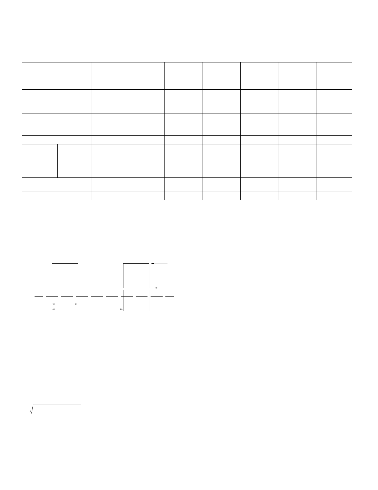
RECOVERY CHARACTERISTICS: A step load
change from 50% to 100% produces less than +4% output
excursion. Recovery occurs to within +1% of the original
setting in <2 ms (load change tr or tfequal to or greater
than 50µsec).
START-UP TIME: 500 ms. maximum.
HOLDUP TIME:
-1UR: 20 ms. typ. (120V a-c), 15 ms. min (100V a-c);
Options T, C, X and Y, all except 3.3V and 28V mod-
els: 30ms typ. (20ms min.);
Options T, C, X and Y, 3.3V model:
55ms typ., 40ms min.;
Options T, C, X and Y, 28V model:
35ms typ., 25ms min.
DIELECTRIC STRENGTH:
Between input and output: 2KV a-c (3KV a-c for
Options T, C, X and Y) for one minute.
Between input and output with Y-capacitor removed:
3.75KV a-c for one minute.
Between input and case (ground): 2KV a-c for one
minute.
INSULATION RESISTANCE: Between input and
ground, output and ground, input and output;
100 Megohms min. (500V d-c).
LEAKAGE CURRENT
-1UR Models:
UL method, 120V a-c: 0.5 mA maximum;
VDE method, 240V a-c: 0.75 mA maximum.
Options T, C, X and Y:
120V a-c and 60 Hz (in conformance with Den-An):
0.28mA typ, 0.45mA max;
240V d-c and 60 Hz (in conformance with IEC 950
and UL1950)0.38mA typ, 0.6mA max.
SAFETY: UL 60950-1, 1st Edition, 2007-10-31; CSA
C22.2 No. 60950-1-03, 1st Edition, 2006-07; EN 60950.
Units are CE marked per the Low Voltage Directive (LVD),
73/23/EEC and 93/68/EEC. [The standards do not apply
with DC input operation]
EMI: Designed to meet FCC Class B (100-120V a-c) and
VDE 0871 Class B (220-240V a-c).
VIBRATION: (non-operating, one hour on each one of
the three axes): 5-10 Hz, 10 mm amplitude, 10-55
Hz, 2g acceleration.
SHOCK: (non-operating, one-half sinusoidal pulse, three
shocks to each axis): Acceleration: 20g, Duration:
11ms +5ms
OPERATING TEMPERATURE: See Figure 5.
STORAGE TEMPERATURE: -40oC to +75oC.
OPERATING AND STORAGE RELATIVE
HUMIDITY: up to 95% (wet bulb temp. <35oC non-con-
densing).

6228-1563 REV 10 083013
KEPCO, INC. 131-38 SANFORD AVENUE FLUSHING, NY. 11355 U.S.A. TEL (718) 461-7000 FAX (718) 767-1102
http://www.kepcopower.com email: hq@kepcopower.com
FUSE: -1UR: Quick acting 3.0A, 250V; (5.2 x 20mm),
San-O P/N MT4 3A; Kepco P/N 541-0110.
T, C, X, Y Models:Wickmann P/N C1-372-2.0A,
Kepco P/N 541-0136.
DIMENSIONS: See Figure 7.
WEIGHT: -1UR Models: 1.5Lbs (0.7Kg);
T, C, X and Y Models: 1.25Lbs (0.57Kg).
WARRANTY: 5 years.
FIGURE 5. % OUTPUT POWER RATING VS.
AMBIENT TEMPERATURE
IV — INSTALLATION
MOUNTING THE POWER SUPPLY. Refer to Figure
6 and insert HSF-1UR power supply in selected slot until
power supply front panel is flush with rack adapter chassis
and secure with two front panel mounting screws.
CAUTION: Do not overtighten these screws: max.
torque is 2 in.-lbs. (0.23 N x m).
CONNECTIONS. All connections are made at the rear
panel of the RA 19-1U Rack Adapter (see RA 19-1U
Operator Manual). Connect the load to the applicable ±
DC OUTPUT terminals. AC input power is applied via two
INPUT POWER terminal blocks: one supplying slots 2
and 4, the other supplying slots 1 and 3. Make sure to
connect the AC input Neutral, Line and Ground wires to
the respective terminals of the terminal blocks.
REMOVAL. To remove a power supply, first use the
POWER switch to turn off the unit. Then loosen the two
mounting screws and extract the unit from the RA 19-1U
Rack Adapter. CAUTION: The ON/OFF switch must be
set to OFF before removing the unit from the rack
adapter.
V — OPERATION
Turn the unit on using the front panel POWER switch (see
Figure 6). CAUTION: DO NOT repeatedly toggle the
POWER on/off switch as this may cause unit to fault.
When output voltage is available, the VDC ON LED is on
(green). All 50W models use convection cooling and do
not include a fan.
While monitoring output voltage at the front panel test
points, the Output Voltage Adjust trimmer allows adjust-
ment of the output voltage.
The 3.3V models do not use forced current sharing so the
MASTER ON LED is always off. The MASTER ON LED
for 5V through 48V models goes on under any of the three
following conditions:
• Independent operation.
• Operation in a parallel master/slave configuration
to indicate which unit is the master.
• Operation in a parallel master/slave configuration
to indicate that a slave unit is no longer within the
proper specifications for paralleled units. Slave 1
should be optimally adjusted to 40mV less than
master, slave 2 adjusted to 40mV less than slave
1, etc. The maximum allowable difference
between paralleled units is 250mv. The minimum
allowable difference between paralleled units is
25mV. If a slave exceeds these limits, the MAS-
TER ON light goes on.
FIGURE 6. COMPONENT LOCATIONS
NOTE:
Safety agency approvals apply only to operation up to 40°C.
3043412
POWER
SWITCH
TEST
POINTS
VOLTAGE
ADJUST
TRIMMER
MASTER
ON
LED
VDC
ON
LED
MOUNTING
SCREW
MOUNTING
SCREW
NOTE: MOUNTING SCREW MAX TORQUE: 2 IN.-LBS. (0.23 N x m)

KEPCO, INC. 131-38 SANFORD AVENUE FLUSHING, NY. 11355 U.S.A. TEL (718) 461-7000 FAX (718) 767-1102
083013 228-1563 REV 10 7
FIGURE 7. HSF-1UR 50W POWER SUPPLY OUTLINE DRAWING
5. TOLERANCES (UNLESS OTHERWISE SPECIFIED):
3 PLACES: ±0.005, 2 PLACES: ±0.01, FRACTIONS: ±1/64"
1.131 [28.7]
3.960 [100.6]
++++
+S
+S
+S
+SNNNN
LLLL
--S
--S
--S
--S
NOTES:
13.050 [331.5]
1.474 [37.4]
0.471 [12.0]
0.010 [0.3]
0.076 [1.9]
0.140 [3.6]
1.732 [44.0]
4.295 [109.1]
0.437 [11.1]
0.780 [19.8]
0.156 [4.0]
1.125 [28.6] 0.750 [19.1]
4. DIMENSIONS ARE IN INCHES, [DIMENSIONS IN BRACKETS
ARE IN MILLIMETERS].
FRONT PANEL -KEPCO DUAL TONE GRAY
C) FRONT PANEL 0.090 THK. ALUM. 6061-T6
A) BACKPLATE 0.064" THK. ALUM. 5052-H32
3. MODULE IS KEYED AS SHOWN IN DETAIL
0.591 [15.0]
1. MATERIAL:
B) PCB 0.063" THK FR-4
2. FINISH:
KEYPINLOCATION
48VOLTS
28VOLTS
24VOLTS
15VOLTS
5VOLTS
3.3VOLTS
12VOLTS
0.129 [3.3]
3.755 [95.4]
0.303 [7.7]
0.690 [17.5]
4.275 [108.6]
0.260 [6.6]
=PINPRESENT
=PINMISSING
14.131 [358.9]
0.507 [12.9]
1.088 [27.6]
0.191 [4.9]
0.190 [4.8]
0.125 [3.2]
1.406
[35.7]
0.228
[5.8]
0.250
[6.4]
0.140
[3.6]
0.140
[3.6]
0.507
[12.9]
0.391
[9.9]
1.732
[44.0]
0.503 [12.8]
0.282 [7.2]
MAX MOUNTING
TORQUE:
2 IN.-LBS (0.23 N x m)
1.108 [28.2]
0.066 [1.7]
0.133 [3.4]
0.125 [3.2]
0.250 [6.4]
0.140 [3.6]
3043062
Table of contents
Other KEPCO Power Supply manuals

KEPCO
KEPCO BHK 500-0.4MG User manual

KEPCO
KEPCO EFX 150-T User manual

KEPCO
KEPCO BOP-GL 1KW User manual

KEPCO
KEPCO RBX SERIES User manual

KEPCO
KEPCO MSK 10-I0M User manual

KEPCO
KEPCO HSF 24-50A User manual

KEPCO
KEPCO FPD 10 Watt User manual

KEPCO
KEPCO KFD 24-4.2-28W User manual

KEPCO
KEPCO HSP Series User manual

KEPCO
KEPCO ATE 1/4 RACK User manual

KEPCO
KEPCO HSF 12-12 User manual

KEPCO
KEPCO HSF A User manual

KEPCO
KEPCO KIT 219-0548 User manual

KEPCO
KEPCO JQE 25-20MVPY-27274 User manual

KEPCO
KEPCO TBC 12-50M User manual

KEPCO
KEPCO HSF 5-10-1U User manual

KEPCO
KEPCO KLP 600-4-1.2K User manual

KEPCO
KEPCO ATE-DMG User manual

KEPCO
KEPCO KLP SERIES User manual

KEPCO
KEPCO HSM 24-42 User manual