KEPCO KIT 219-0548 User manual

©2015, KEPCO, INC 1
Data subject to change without notice 228-1744 REV 3
INSTRUCTION MANUAL
BOP 1000W
KEPCO
KEPCO, INC. 131-38 SANFORD AVENUE FLUSHING, NY. 11355 U.S.A. TEL (718) 461-7000FAX (718) 767-1102
http://www.kepcopower.com email: hq@kepcopower.com
An ISO 9001 Company. Transition Circuit
KIT 219-0548
BOP 6-125MG
TRANSITION CIRCUIT KIT
1. DESCRIPTION
Kepco KIT 219-0548 contains components used for a field upgrade of BOP 6-125MG power supplies to allow
smoother transitions through zero power when driving inductive loads at low frequencies and/or at a low rate of
output power changes. This upgrade avoids possible faults under these conditions which can cause the unit to dis-
play an error and reduce output power to zero.
The Transition circuit detects when the voltage and the current at the BOP output have opposite signs, showing
that the unit is beginning to sink power. This turns on a preload placed between the Front End Module and the Out-
put Module of the BOP. If the Sink power increases to the point that the Source-Recuperation Detector is triggered,
the Front End switches to Sink-Recuperation mode at an increased level of power, as the preload is turned off by
the Source-Recuperation Detector. This permits a sharper transition towards Sink-Recuperation mode. If the Front
End switches to Source mode, the preload is activated for a predetermined period of time in order to boost the
power requested from the Front End, resulting in a sharper transition towards the Source mode.
2. APPLICABILITY
This KIT applies only to BOP 6-125MG models. Contact Kepco for kits applicable to other models. This manual
applies only to Rev 2 Transition Circuit Assemblies.
3. INSTALLATION INSTRUCTIONS
3.1 MATERIAL SUPPLIED (See Table 1.)
TABLE 1. MATERIAL SUPPLIED
MATERIAL KEPCO PART NUMBER QUANTITY
Transition Circuit assembly (A7A3)
comprised of (1) Printed Circuit Board assembly (236-
3069), (1) Heat Sink assembly (136-0481) and other related
components
300-0535 1
Screw, PHPH, 6-32 x 0.5 in. 101-0519 2
Cable Assembly, A2A5 to A7A3J1 (5-Pin connector) 118-1265 1
Cable Assembly, A4A8 to A7A3J3 (4-Pin connector) 118-1266 1
Cable Assembly, A4A8 to A7A3J4 (3-Pin connector) 118-1267 1
Resistor, 150KOhms, 1%, 1/8W (R59) 115-2597 1
Resistor 200KOhms, 1%, 1/4W (R58, R70) 115-2809 2
Cable Tie 138-0076 5
Adapter Plate 128-2412 1
Screw, FLPO, 6-32, 0.375 IN., ST 101-0332 2
Self-adhesive Plastic Mount Cable Tie 138-0089 3
Instruction Manual 228-1744 REV 3 1

2228-1744 REV 3 080515
KEPCO, INC. 131-38 SANFORD AVENUE FLUSHING, NY. 11355 U.S.A. TEL (718) 461-7000FAX (718) 767-1102
http://www.kepcopower.com email: hq@kepcopower.com
3.2 COVER REMOVAL PROCEDURE
WARNING: Before installing the kit, unplug the BOP from a-c input source and disconnect the output
load!
1. Turn power off and disconnect the unit from source power and remove line cord, then disconnect the output
load.
NOTE: Retain all hardware for reassembly.
2. Remove the two mounting ears from the chassis by removing three screws from each.
CAUTION: The two screws at the top of the front panel must be removed first to avoid damage to the
front panel.
3. Remove the top cover of the unit by removing 14 screws as follows: two at top of the front panel, four at each
side, (one towards the rear, three at the bottom) and four at the top of the rear panel.
3.3 PRINTED CIRCUIT BOARD AND HEAT SINK INSTALLATION PROCEDURE
The Transition Circuit Assembly (A7A3) is shipped with Printed Circuit Board (PCB) assembled to the Heatsink
with the preload-MOSFET mounted directly on the heatsink (Figure 1).
FIGURE 1. TRANSITION CIRCUIT ASSEMBLY, COMPONENT LOCATIONS
1. Attach the adapter plate provided in this kit to the Transition Circuit assembly heat sink using two flat head
screws (P/N 101-0332) provided in this kit.
2. Install the Transition Circuit assembly as shown in Figure 2 by sliding the adapter plate under the fan and
using the two screws provided in this kit at the ventilation holes identified in the figure. The screws are inserted
up through the bottom of the chassis into the adapter plate.
CAUTION: When routing cables, ensure that the cables stay clear of the Output Module (A2) Fan and
Auxiliary Power Supply (A5).
3. Cable assembly P/N 118-1267 (provided in the Kit) has a 3-pin connector with two wires, each having non-iso-
lated ring lugs. Remove the screws and lockwashers from J4M and J2M on A4A8, then add the wires from the
cable assembly to the wires already connected to J4M and J2M as follows (see Figure 2 for the location of
A4A8 in the chassis, Figure 3 for location of J4M and J2M and Figure 6 for cable routing):
• red/white wire to A4A8- J4M
• black/white wire to A4A8- J2M
!
R28
C12
Q6
1
2
Q2
!

080515 228-1744 REV 3 3
KEPCO, INC. 131-38 SANFORD AVENUE FLUSHING, NY. 11355 U.S.A. TEL (718) 461-7000FAX (718) 767-1102
http://www.kepcopower.com email: hq@kepcopower.com
FIGURE 2. BOP 1KW COMPONENT LOCATIONS
4. Install the 4-pin cable assembly (P/N 118-1266) on Transition Circuit A7A3J3 of the PCB (see Figure 1). Route
the cables as shown by Figure 6. This cable has three (3) unterminated wires. Determine the needed length,
cut the wire and remove the insulated sleeving (approximately 0.15"), then solder each wire to the indicated
point (see Figure 3 for A4A8 component locations and Figure 6 for cable routing):
• red wire to A4A8D1 Cathode
• black wire to A4A8D1 Anode
• white wire to A4A8TP2
3043897
CHASSIS GROUND CONNECTION
SCREW (QTY 2), PHPH,
6-32 X 0.5 IN., ST
KEPCO P/N 101-0519
TRANSITION CIRCUIT
ASSEMBLY A7A3
A2A5 ASSEMBLY
(SEE FIGURE 4.)
A4A3 ASSEMBLY
(SEE FIGURE 3.) A1 ASSEMBLY
(SEE FIGURE 2.)
OUTPUT MODULE
(A2) FAN
NOTE:
TO MOUNT TRANSITION
CIRCUIT ASSEMBLY A7A3
INSERT ONE SCREW IN
VENTILATION HOLE A, THE
OTHER IN HOLE B. IF THE
CHASSIS BOTTOM MUST
BE FLUSH TO A FLAT
SURFACE, THE CHASSIS
HOLES A AND B MUST BE
COUNTERSUNK. (PARTIAL TOP VIEW)
B
(SEE NOTE.)
FAN MOUNTING
SCREW
A
(SEE NOTE.)
FRONT
PANEL

4228-1744 REV 3 080515
KEPCO, INC. 131-38 SANFORD AVENUE FLUSHING, NY. 11355 U.S.A. TEL (718) 461-7000FAX (718) 767-1102
http://www.kepcopower.com email: hq@kepcopower.com
FIGURE 3. A4A8 COMPONENT LOCATION/WIRING
5. Install the 5-pin cable assembly (P/N 118-1265) on Transition Circuit A7A3J1 (see Figure 1) of the PCB. Route
the cables as shown by Figure 6. This cable assembly has a 5-pin connector with five (5) unterminated wires.
Determine the needed length, cut the wire and remove the insulated sleeving (approximately 0.15"), then sol-
der each wire to the indicated point of assembly A2A5 (see Figure 4 for location of wire attachment points and
Figure 6 for cable routing):
• white/yellow wire to A2A5D26 Anode
• white/blue wire to junction of A2A5R40 and J3, pin 6
• black wire to A2A5TP1
• red wire to A2A5TP7
• white wire to A2A5TP8
FIGURE 4. A2A5 COMPONENT LOCATION

080515 228-1744 REV 3 5
KEPCO, INC. 131-38 SANFORD AVENUE FLUSHING, NY. 11355 U.S.A. TEL (718) 461-7000FAX (718) 767-1102
http://www.kepcopower.com email: hq@kepcopower.com
6. To gain access to the components of A4A3 in order to replace R58, R59 and R70, first remove A4A3 from the
chassis as follows:
a. At top of A4A3 disconnect nine cables from J1 through J9 of A4A3 (Figure 5).
b. Remove four screws attaching A4 assembly to the chassis.
c. Remove five screws and five washers attaching A4A3 board to A4A1 board and remove A4A3 board.
7. Unsolder and remove the following three resistors from A4A3 and replace with the resistors supplied as fol-
lows (see Figure 5 for location of A4A3 components):
• Install and solder replacement R59 supplied: P/N 115-2597 (150K Ohms, 1%, 0.125W)
• Install and solder replacement R58 and R70 supplied: P/N 115-2809 (200K Ohms, 1%, 0.25W)
FIGURE 5. A4A3 COMPONENT LOCATIONS
8. Reinstall A4A3 by following the reverse of step 6 above.
9. Perform visual inspection of transition circuit installation.
CAUTION: After installing all components and wiring as described above, perform the following
checklist to verify that installation has been done correctly.
• Verify that cable wires are connected properly and to the correct termination
• Check for unintentional short-circuits between the wire connections and adjacent components, pads and
traces.
• Use an ohmmeter to verify that the Transition Circuit heatsink is isolated (more than 1Megohm resistance)
from the BOP chassis.
• Verify that the Transition Circuit is securely attached to the BOP chassis.
• Verify that the Transition circuit cables are clear of the Output Module (A2) Fan and Auxiliary Power Supply
(A5).
!

6228-1744 REV 3 080515
KEPCO, INC. 131-38 SANFORD AVENUE FLUSHING, NY. 11355 U.S.A. TEL (718) 461-7000FAX (718) 767-1102
http://www.kepcopower.com email: hq@kepcopower.com
FIGURE 6. TRANSITION CIRCUIT ASSEMBLY, CABLE ROUTING
NOTE: Components shown are typical; arrangement may differ depending on unit revision.

080515 228-1744 REV 3 7
KEPCO, INC. 131-38 SANFORD AVENUE FLUSHING, NY. 11355 U.S.A. TEL (718) 461-7000FAX (718) 767-1102
http://www.kepcopower.com email: hq@kepcopower.com
3.4 VERIFICATION MEASUREMENTS
Prior to shipping, the Transition Circuit has been tested in a BOP 1KW. The following measurements ensure that
the Transition circuit has been installed correctly, or for debugging. Table 2 lists the test equipment needed to per-
form these measurements.
3.4.1 A7A3R5 Measurement
1. With the unit turned off, connect a DVM (set for DC voltage measurements) to Transition Circuit A7A3R5 (end
closest to A7A3J1; see Figure 1), referenced to TP2.
2. Install the power cord and connect the BOP to source power.
3. With no load connected, turn on the unit, then set the BOP to voltage mode, enable the output and program
the output voltage to positive full scale (6V).
4. Set the current limit to the full scale value (125A).
5. Verify that the DVM measures –10V ±0.5V.
6. Set the output voltage to negative full scale and verify that the DVM measures +10V ±0.5V. Turn off the unit.
3.4.2 A7A3TP3 Measurement
1. With the unit turned off, connect the DVM to Transition Circuit A7A3TP3, referenced to TP2.
2. Install a short-circuit across the BOP output.
3. Turn on the unit, then set the BOP to current mode, enable the output and program the output current to posi-
tive full scale (125A).
4. Set the voltage limit to the full scale value (6V).
5. Verify that the DVM measures +10V ±0.1V.
6. Set the output current to negative full scale. Verify the DVM measures –10V ±0.1V, then turn off the unit
3.4.3 A7A3R17 Measurement
1. With the unit turned off, connect the DVM across A7A3R17 (reference lead connected to the resistor end near-
est to A7A3J4).
2. Disconnect the short-circuit from the output and connect a resistive load RL (see Table 2) across the output.
Turn on the unit, set voltage mode, enable the output and program the output voltage to positive full scale. Set
the current limit to the full scale value. The DVM should measure 0V ±10mV. Turn off the unit.
3. With the unit turned off, leave the DVM across A7A3R17 and connect a scope probe to A7A3D3 anode (refer-
enced to the end of resistor A7A3R17 nearest to A7A3J4). Set the scope for 1V/div, 5ms/div, normal triggering
(positive edge, single).
4. Disconnect the load from the output and connect a variable power supply PS (see Table 2) to the BOP with PS
positive terminal to BOP OUT terminal and PS negative terminal to BOP COM terminal. Set the PS for to the
nominal output voltage of the BOP (6V), and set PS current limit value to minimum (zero).
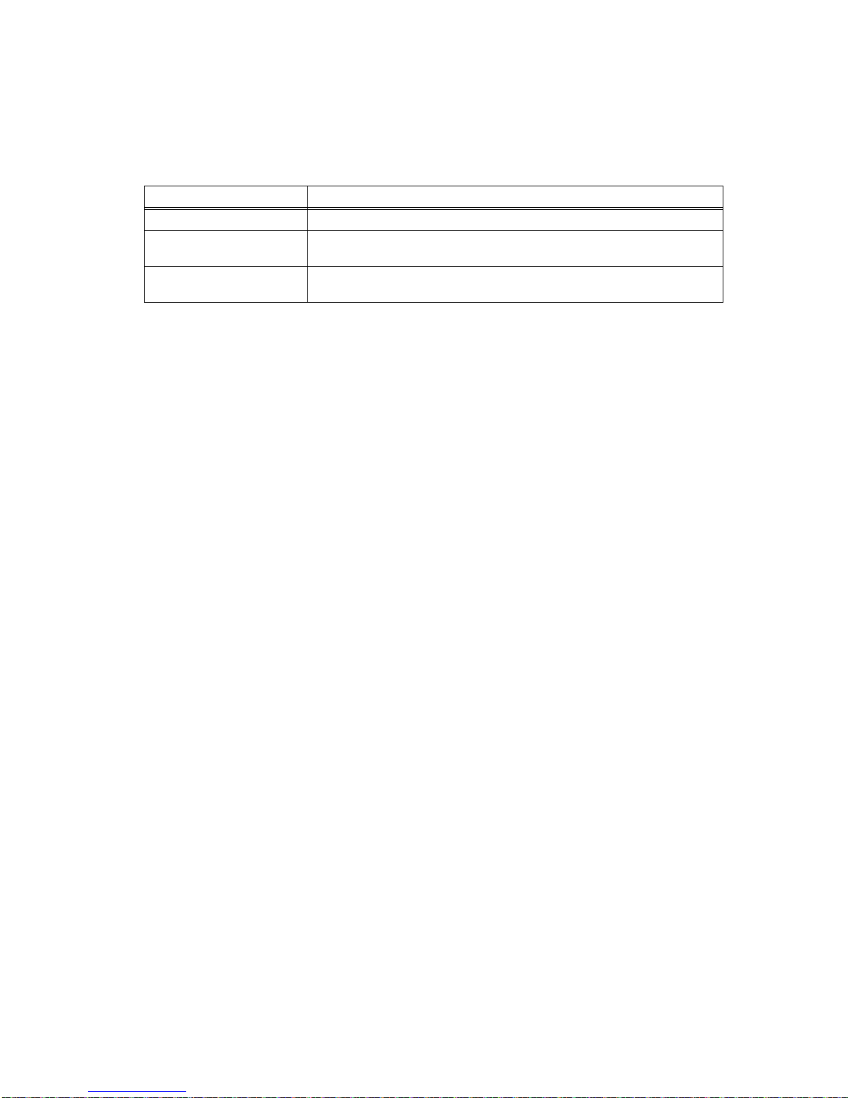
TABLE 2. TEST EQUIPMENT REQUIRED
Test Equipment Requirement
Digital Voltmeter (DVM) Voltage measurements (d-c)
Resistive Load (RL) Value (Ohms) = 200 x Nominal Output Voltage / Nominal Output Current
(RL = 10 Ohms, 10W).
Variable Power Supply (PS) Unipolar, adjustable, able to deliver Nominal Output Voltage of 6V with an adjust-
able current limit having a maximum value of at least 20A.

8228-1744 REV 3 080515
KEPCO, INC. 131-38 SANFORD AVENUE FLUSHING, NY. 11355 U.S.A. TEL (718) 461-7000FAX (718) 767-1102
http://www.kepcopower.com email: hq@kepcopower.com
5. Turn on the BOP, set voltage mode, enable the output and program a positive output voltage of +5.5V value
and set the current limit to full scale (125A).
6. Gradually increase the PS current, monitoring the DVM/ scope and the BOP front panel display and/or the
internal LED indicators DS3 and DS2 on A3A4 (see Figure 5 for location of LEDs). DS3 is green and goes on
when the Front End Module is in source mode of operation. DS2 is yellow and goes on when the Front End
Module is in sink (recuperation) mode of operation.
7. When PS current reaches approximately 0.13A ±0.04A, note that the DVM indication jumps from zero to
+1.24V ±0.3V.
8. When PS current reaches approximately 16.2A ±.2.4A, green LED indicator A4A3DS3 goes off, yellow LED
A4A3DS2 goes on, the BOP display changes the message flag from “SOURCE” to “SINK” and the DVM jumps
from +1.24V to zero.
9. Gradually decrease PS current. When PS current reaches approximately 5.1A ±0.8A, green LED indicator
A4A3DS3 goes on, yellow LED A4A3DS2 goes off, the BOP display changes the message flag from “SINK” to
“SOURCE” and the scope will show a 15V, 5mS positive pulse.
10. Turn off the unit and disconnect all the test equipment from the BOP. Unplug the unit from the a-c input source.
3.5 REASSEMBLY PROCEDURE
CAUTION: The two screws at the top of the front panel must be installed last to avoid damage to the
front panel.
1. Attach the cover to the chassis using 14 screws.
2. Attach the two mounting ears to the chassis using three screws for each.
3. Install the power cord and connect the unit to source power.
3.6 CONNECTING MULTIPLE UNITS
If multiple BOP 6-125MG units are connected in either series or parallel, it is recommended that the Transition Cir-
cuit Assembly be installed in all units. If the Transition Circuit Assemblies are a mix of Rev 1 and Rev 2, it is rec-
ommended that a unit with a Rev 2 Transition Circuit Assembly be selected as the master.
!
Table of contents
Other KEPCO Power Supply manuals

KEPCO
KEPCO JQE 55-20 (m) User manual

KEPCO
KEPCO HSF 5-20 User manual

KEPCO
KEPCO ERD150W-24 User manual

KEPCO
KEPCO FPD 50W-24V User manual

KEPCO
KEPCO RTW 300W SERIES User manual

KEPCO
KEPCO BOP 3/4 RACK User manual

KEPCO
KEPCO HSF-PFC Series User manual

KEPCO
KEPCO PAT 7-2 User manual

KEPCO
KEPCO FAW 5-30K User manual

KEPCO
KEPCO KLP 600-4-1.2K User manual

KEPCO
KEPCO BOP 1000W User manual

KEPCO
KEPCO BOP 500M User manual

KEPCO
KEPCO TBC 12-50M User manual

KEPCO
KEPCO BOP-2KW MG User manual

KEPCO
KEPCO HSF A User manual

KEPCO
KEPCO EFX 100-T User manual

KEPCO
KEPCO APH Series User manual

KEPCO
KEPCO PTR Series User manual

KEPCO
KEPCO JBW 05-3R0 User manual

KEPCO
KEPCO KLN Series User manual