KERR ENDODONTICS Apex Connect User manual

Apex
Connect
INSTRUCTIONS FOR USE
ELECTRONIC APEX LOCATOR

1
en - ENGLISH
Apex Connect
ELECTRONIC APEX LOCATOR
CONTENTS OVERVIEW
1All Components
Apex Connect Unit Probe Cord File Holder Adapter Lip Hook (5)
File Holder A File Holder B AC/DC Adapter Power Cord
APEX CONNECT UNIT
No. Name Function
1Power button Turns on the main body. To turn off the power, press and hold the [ ] button for 2 seconds.
2USB connector
terminal Use probe cord to connect the file holder and lip hook to the main body.
3Display Screen Displays the main body status and the measured value of the root canal length while the main body is in use.
4Settings button Press and hold the [ ] button to enter the settings mode.
• In the settings mode, the APEX can be set for the reference value, sound volume, and standby time
5Select button In the settings mode, change the settings.
6Battery cover There is a built-in rechargeable battery that supplies power.
7Charging terminal Connects the power cord and AC/DC adapter to charge the battery.
LCD SCREEN
The measurement screen is the screen that appears on the display when the device is turned on. On this screen, the device can be checked and
the root canal length read and set the usage environment.
No. Description
1Volume icon. The alert sound volume is displayed.
2Battery Icon. The remaining battery charge is displayed.
3Measurement information of the root canal length. The current location of the file in the root
canal is displayed in a number and a graph.

2
PROBE CORD
No. Name Function
1Lip hook connector Install the lip hook.
2USB connector (H) Connects to the file holder.
3USB connector (A) Connects to the Apex Connect unit
INDICATIONS FOR USE
Apex Connect is an Electronic Apex Locator designed to measure
the working length of root canals.
CONTRAINDICATIONS
•Do not use this device on patients with pacemakers or nerve
regulators. Also, do not use this device on patients who are
sensitive to metals such as stainless steel.
•Do not use this device in the presence of oxygen oxides,
nitrogen oxides, or flammable anesthetic mixtures
containing air. There is a risk of explosion.
SAFETY PRECAUTIONS
To ensure the safety of users and patients and to use the device
properly, be sure to read the contents of this instructions for use
before using the device.The manufacturer is not responsible for
any injuries or damage caused by not following the precautions.
The most important thing when using medical devices is the
safety of all users, including patients and medical staff members.
Please read the following safety information thoroughly to
identify and prevent potential hazards.
WARNING
May cause serious damage or severe injury such as death if
not followed.
PRECAUTION
May cause physical injury or property damage, as well as, indicates
unsafe procedures or cases where the device may be damaged.
WARNINGS
•For use by qualified and trained dental personnel only.
•U.S. federal law restricts the sale of this device to or on the
order of a healthcare professional.
•Do not use this device with electric surgical devices.
•Use of other accessories that are not authorized for use in
connection with this device may cause malfunction and
compromise patient safety.
•Do not use the device in a place that it is exposed to direct
sunlight, heat sources, or near a fire. The battery may
explode or cause a fire.
•Never use a damaged cable. There is a risk of fire or
electric shock.
•Be sure to connect the power plug to a grounded power
supply. There is a risk of fire or electric shock.
•Do not touch electrical parts with wet hands. There is a risk
of electric shock and injury.
•To prevent accidental aspiration, the use of a rubber dam is
strongly recommended.
•Use the battery, AC/DC adapter, and power cord included in
the package. Only use Kerr Endodontics batteries designated
for this system. Use of other batteries may damage the
device(s) or cause a malfunction.
•Ensure conductors such as metal are not in contact with
the metal part of the device. There is a risk of device
malfunction, fire, or electric shock.
•Do not disassemble the device. Direct physical contact with
the inside of the device can cause electrical shock and burns.
•Do not repair, modify, or disassemble the device, except for
authorized service engineer or a specialist who has received
repair training. Product failure or damage caused by
unauthorized actions is not subject to free service and
warranty service.
•When transporting the device, use the original packaging
provided by manufacturer to prevent accidental activation
of the unit or any damage to the device itself.
•Air or land transportation of the device is permitted in the
original packaging container.
•For shipping batteries within the United States or
Internationally, consult the Department of Transportation’s
Pipeline and Hazardous Materials Safety Administration or
the International Air Transport Association guidelines.
PRECAUTIONS
•Do not use this device for any purpose other than its
intended use. The manufacturer is not responsible for any
injuries or damage caused by this.
•This device is not waterproof. Do not submerge or directly
contact the device with water. There is a risk of electric
shock or device malfunction.
•Do not connect unsupported types of devices. The device
may break down or malfunction.
•When using or moving the device, do not throw or drop it.
The device may break down or malfunction.
•When using, be fully aware of the protective measures for
the patient and be prepared for possible risks.
•Check the patient's condition and device operation
during use.
•If the device is dropped during use, ensure that there is no
danger to the patient or user.
•For long-term storage, keep the device in a clean and
dry place, where the temperature and humidity do not
change easily.
•If there are sign of smoke or burning, turn off the power
immediately, and take appropriate measures.
•If the device breaks down or has a problem, stop using it
immediately, and contact customer services.
ADVERSE REACTIONS
None known.
SYMBOL DESCRIPTION
Full explanation of symbols used on Kerr packaging is located at:
http://www.kerrdental.com/symbols-glossary
Serial number
Authorized representative in the European Community
Manufacturer
CE - Mark and identification number of notified body.
Product conforms to the essential requirements of the
Medical Device Directive 93/42/EEC
Type BF Applied Part
Humidity limitation
Fragile, handle with care
This way up
Sterilizable up to the stated temperature

34
Warning
WEEE Marking
Catalogue number
Medical Device
CAUTION: Federal law restricts this device to sale by or
on the order of a dentist
Date of manufacture
CSA Mark with “C/US”Indicator for Certified Products
Temperature limit
Atmospheric pressure limitation
Keep dry
Refer to instruction manual
Caution
STEP-BY-STEP INSTRUCTIONS
PRECAUTION
The components and devices have not been disinfected or
sterilized prior to shipping. Please perform the necessary
cleaning and disinfection steps prior to patient treatment.
GETTING STARTED
Remove the device, file probes, AC/DC adapter, and power cord
from their packaging.
1Charging the Battery
•When using the device for the first time or after long-term
storage, charge the battery sufficiently before use.
•After connecting the power cord and AC/DC adapter, plug
the AC/DC adapter into the charging terminal on the right
side of the device and plug the power cord into the power
supply. The battery icon appears on the display.
•When charging is complete, the battery icon stops blinking
and stays on.
WARNING
• Charge using the AC/DC adapter and power cord included in
the package.
• Be sure to connect the power plug to a grounded power supply.
PRECAUTION
This device is designed to not operate while charging.To use the
device, disconnect the AC/DC adapter from the device.
INITIAL SETUP
1Assembling the Device
a. Attach the lip hook and file holder to the probe cord, and
then connect it to the body.
b. Insert the USB connector (H) of the probe cord into file
holder B and insert the lip hook into the lip hook connector.
Or connect holder A using the holder Adapter
c. Plug the USB connector (A) of the probe cord into the Apex
Connect unit USB connector.
PRECAUTIONS
• The USB connector (Type C) on the probe cord has its intended use.
Examine each connector and connect to the appropriate device.
• Single USB connector (A): connects to the Apex Connect unit
• USB connector (H) connects to the file holder
2Disassembling the Device
1. Pull the lip hook from the lip hook connector on the probe
cord to remove.
2. Pull out the USB connector at both ends of the probe cord
from the Apex Connect Unit and file holder B.

34
3. If using File Holder A, remove File Holder A from the File
Holder Adapter and disconnect the File Holder Adapter from
the Probe Cord.
PRECAUTION
After using the device, refer to “Autoclavable Components:
Lip hook, File holder A and File holder B.”
3Turning the Device On/Off
Press the [ ] button on the left side of the device without
the file holder and lip hook touching anything. The device is
connected to power and turns on the display.
a. Once powered on, the calibration function will run
automatically. [CAL] flashes while the device is
being calibrated.
b. When calibration is complete, the measurement screen
appears on the display.
c. If the calibration function is not executed, Er will flash on
the measurement screen.
d. To end use, press and hold the [ ] button. The display
turns off.
PRECAUTION
If the device is powered on while the file holder and lip hook are
touching the object, the calibration function will not start, and
[Er] is displayed on the measurement screen.
NOTE:
Calibration is completed in about 10 seconds, if the
measurement screen does not appear after 10 seconds,
contact Kerr Customer Care.
PRECAUTION
After using the device, refer to “Cleaning, Disinfection and
Sterilization Instructions”section to properly manage
the device.
PREPARING THE DEVICE
1Preparation and Use Environment
The environmental information appropriate for using this device
is as follows.
•Appropriate temperature: 10–35°C (50–95°F) / Appropriate
humidity: 30–75% / Atmosphere pressure: 700–1060 hPa
•Do not use the device in a place that it is exposed to direct
sunlight, heat sources, or near a fire.
2Assembly
•Charge the battery sufficiently when using the device for the
first time or after long-term storage.
•Be sure to charge the battery using the power cord and
AC/DC adapter included in the package.
•Sterilize the lip hook and file holder when using the device
for the first time and after every patient.
•Examine the role of each USB connector on the probe cord
and connect to the appropriate device.
•Ensure the file holder and lip hook are properly connected
to the probe cord.
NOTE:
•Refer to “Charging the Battery”on page 3 for more
information on how to charge and replace the battery.
•Refer to “Assembling the Device”on page 3 for more
information on how to mount and remove the lip hook and
file holder.
USING THE DEVICE
1. Refer to “Initial Set-up”to connect the lip hook and file
holder to the device.
2. To turn on, press the [ ] button on the left side of the
device without the file holder and lip hook touching
anything.
PRECAUTION
If the device is powered on while the file holder and lip hook are
touching the object, the calibration function will not start, and
[Er] is displayed on the measurement screen.
3. With the clip of the file holder B touching the lip hook,
ensure that the figures and graphs are activated on the
measurement screen.
4. While holding down the [Push] button on file holder B,
insert the file according to the shape of the clip.
PRECAUTIONS
• Use a stainless-steel hand file (k-file).
• Do not use deformed or damaged files.
5. Gently pull on the file to confirm it is secured.

56
PRECAUTION
If the file is not properly secured to the file holder, the file may
become detached during use and may result in inaccurate readings.
6. Place the lip hook on the lip opposite the tooth to be
worked on.
7. Slowly insert the file into the root canal, checking the
information on the measurement screen.
• Refer to “Measuring Working Length”on to measure
the length of the root canal.
• When measuring with file holder A, confirm that the file is
connected to the metal part under the file handle.
PRECAUTIONS
• When measuring the root canal length, the file length may vary
depending on the operator's viewing angle.
• After root canal instrumentation, the length of the file may differ
from the measured angle of the original working length. After
instrumenting the root canal, check the working length again.
8. When finished, press, and hold the [ ] button for
2 seconds. The display turns off.
9. Press the [Push] button on the file holder B to remove the
file from the clip.
10. Refer to “Disassembling the Device”to remove the lip
hook and file holder from the device.
11. Refer to “Cleaning, Disinfection and Sterilization
Instructions”to manage the device.
1Measuring Working Length
1. Slowly insert the file into the root canal while checking
the readings.
• When the file approaches the APEX reference value, an
alarm beeps.
• When the file reaches or passes the APEX reference
value, the device will sound the alarm continuously and
measurement screen and file holder will flash at the
same time.
• The measured value range and corresponding color will be
shown on the display with the file holder lamp.
See Table Below.
Lamp Color Lamp Status Measured value range (mm)
Blue On 3.0–1.1
Yellow On 1.0–0.1
Red On 0.0– -0.5
2. Once the distance between the file and APEX reaches the
APEX reference value, stop inserting the file, place the
rubber stopper of the file on the reference point of the tooth,
and then remove the file from the tooth.
3. Use an Endo ruler to measure the working length between
the end of the file and the rubber stopper.
NOTE:
Use radiographs to check the working length.
Different results from radiographs than the results obtained from
the measuring device may be shown.This is not a malfunction
of the measuring device. It may be due to the anatomical apex
and/or the physiologic apex may be located coronal to the
radiographic apex, or there was a misalignment of the angle of
the X-ray beam and the film. (See Figure 1)
2Helpful Tips to Avoid Measuring Errors
•Before measuring root canal length, remove any exudates
such as blood from the root canal.
•Before measuring the root canal length, be sure to dry the
pulp chamber around the root canal opening.
•If the root canal is completely dry, the actual length and
measurement may differ. Fill the inside of the root canal
with saline water and measure.
•After inserting the file to approximately half the length of
the root canal, attach the file to the file holder.
•When measuring the root canal length, start working with a
thicker file. If the reading does not reach the APEX point, use
a thinner file to measure the root canal length.
•During root canal length measurement, be mindful of the
errors that may occur if the file touches a metal restoration.
•The presence of necrotic dentition and cementum within
the root canal can affect the measurements. Measure
several times, extending the root canal with a file of the
appropriate thickness.
•If the root canal is not fully formed or is over instrumented,
the measurement of the working length may be shorter
than the actual measurement.
•To obtain a more accurate measurement with minimal error,
measure at least twice.
•If the root canals within the tooth are connected, such as
a multi-root canals or the tooth has a crack, it may affect
the measured value and cause an error. Use a radiograph to
check the structure of the tooth, including cracks
USER ENVIRONMENT SETTINGS
Follow the steps below to set the user environment for the
Apex Connect unit
1. With the device powered on, press, and hold the [ ] button
for about 2 seconds. Entering the settings mode, the figures
and graphs flash on the display.
2. Press the [ ] button to select the APEX reference value, and
then press the [ ] button. The settings are saved, and the
volume icon blinks.
• The APEX reference value is displayed as a line on the graph
on the measurement screen, and this line can be used as an
estimate of the working length of the root canal.

56
• APEX reference value can be set between -0.5 and 1.0 mm.
(Default: 0.0 mm)
• The default setting of the APEX reference value which is 0.0
means that the file has reached the anatomical foramen
(apical constriction) and is approximately 0.5 mm away
from the physiological foramen (apical foramen).
3. Press the [ ] button to select the alarm volume, and then
press the [ ] button. The settings are saved, and the
value flashes.
• Set the alarm volume between 0 and 3. (Default: 2)
4. Press the [ ] button to select the standby time, and then
press the [ ] button. The settings are saved and returned to
the measurement screen.
• Set a standby time so that the device turns off after a
certain period of inactivity.
• The standby time can be set between 2 and 10 minutes, in
2-minute increments. (Default: 4 minutes)
ADVANCED SETTINGS
1Linking the Apex Connect to the Elements
Connect Endodontic Motor
This device can be used in conjunction with Elements Connect
Endodontic Motor, by connecting the two devices, the
instrumentation and enlargement of the root canal can be
performed while checking the working length of the root canal.
PRECAUTIONS
• This device is designed to be compatible with Elements Connect.
Do not connect any device other than Elements Connect.
• Use the USB connection terminal on this device only to connect
Elements Connect and lip hook. Do not connect the charging
USB cable.
2Elements Connect Endodontic Motor
Components
The following components are required to set up the Cordless
endodontic motor:
Contra angle
Motor Handpiece Battery (2)
NOTE:
For more information on the components of the Elements
Connect Cordless Endodontic Motor and how to use them, refer
to the “Elements Connect Endodontic Motor Instructions
for use.”
3Assembly and Connection
1. Plug the USB connector (H) on one end of the probe cord into
the USB connection terminal of the motor handpiece and the
other USB connector (A) into that of the Apex Connect Unit.
PRECAUTIONS
The USB connector (Type C) has specific connectors for each
intended use. Examine the role of each connector and connect to
the appropriate device.
• Single USB connector (A): Apex Connect device connection.
• USB connector (H) supplied with lip hook connector: Motor
handpiece connection.
2. Insert the lip hook into the lip hook connector of the probe cord.
PRECAUTION
Be sure to clean and sterilize the lip hook, File Holder A and File
Holder B before use. Refer to “Cleaning, Disinfection and
Sterilization Instructions”.
3. Refer to “BEFORE USE > Using Accessory”in the Elements
Connect Cordless Endodontic Motor Instructions for use
to attach the contra angle and Ni-Ti file to the motor
handpiece.
PRECAUTION
When selecting the proper file length for the procedure, note that
the total working length of the file is reduced by 2mm due to the
deep set insert in the contra angle head and might difficult the
repositioning of the silicone stopper. A longer file might have to
be selected.
4. Press the [Main] button on the motor handpiece and the
[ ] button on the Apex Connect Device. The power and the
display of both turn on.
5. Check that [EAL] appears on the main screen of the motor
handpiece. If [EAL] appears, it means that the motor
handpiece and main body are properly connected.
4Setting the Linkage
Set the motor operation options when using the device in
conjunction with Apex Connect

78
1. On the main screen of the motor handpiece, press the [ ]
button for 2 seconds. The linkage settings appear.
2. Press the [ ] button until the desired menu appears, then
press the [/]button to select a value.
3. [Auto start&stop]: Set whether to operate the motor
depending on the location of the file.
• [On]: The motor operates when the file is inserted into the
root canal, and the motor stops when the file is pulled out
from the root canal.
• [Off]:The motor does not run even if the file is inserted
into the root canal. Regardless of where the file is, the
[Main] button must be pressed to operate the motor.
4. [Apical action]: When the Apex Connect measurement
approaches the APEX reference value during root canal
instrumentation, the speed of motor and the torque of the
motor decrease so that the root canal does not instrument
deeper than the set value.
• [Speed slowdown]:When the Apex Connect
measurement approaches the APEX reference value,
the motor's rotational speed decreases.
• [Torque slowdown]:When the Apex Connect
measurement approaches the APEX reference value,
the motor's torque limit decreases.
• [Off]:The motor operates the same regardless of whether
or not the Apex Connect measurement approaches the
APEX reference value.
5. Press the [Main] button. The settings are saved, and return
to the main screen.
5Using Linkage
1. Refer to “USING THE DEVICE > Basic functions”in the
Elements Connect Endodontic Motor Instructions for use to
set the memory number and the motor operation method.
2. Place the lip hook on the lip opposite to the tooth being
treated
3. Slowly insert the Ni-Ti file into the root canal. The root canal
length is measured, and the Apex Connect measurement is
displayed in the [EAL] area of the main screen.
NOTE:
To measure root canal length only, [Auto start&stop] must
be set to [Off ]. For more information on how to set the motor
operation, refer to “Setting the Linkage”in this manual.
4. When the [Main] button is pressed on the motor handpiece,
the motor will start, and the operation is displayed in the
motor screen.
• The following information is displayed in the motor
operation screen:
No. Description
1• These values represent the APEX reference value and the
measurements taken by the Apex Connect at the file’s
current location.The measured value is also displayed
numerically on the right side of the screen.
• When the measured value reaches the APEX reference
value, the motor operates as follows.
• [R&S]: The motor stops after rotating in the opposite
direction of the current setting.
• [REV]: The motor rotates in the direction opposite to the
current setting. It then rotates in the set direction again.
2It is the torque value of the motor when operating and the
torque limit value set in the memory.
3[APEX] blinks when the measurement reaches or passes the
APEX reference value.
•Confirm the following information with the Apex Connect Unit.
• If the instrument reading approaches the value of the APEX
reference value, an alarm will beep rapidly.
• If the reading reaches or passes the value of the APEX
reference value, the alarm will beep continuously, and the
screen will blink.
•Confirm the measured value range with the lamps of the
[Main] button on the motor handpiece.
• If the reading reaches or passes the value of the APEX
reference value, the [Main] button of the motor handpiece
will blink.
Lamp Color Lamp Status Measured value
range
(mm)
Blue On 3.0–1.1
Yellow On 1.0–0.1
Red On 0.0– -0.5
•To stop the motor operation, press the [Main] button. The
memory number and motor operation settings are changed
on the main screen.
•If selected [CW], [CCW], [Adaptive], or [RCP]as the motor
operation method, press and hold the [Main] button on the
main screen to rotate the motor in the opposite direction of
the current setting.
• The motor rotates in the opposite direction only while the
button is pressed and stops when release it.
• Here, the operation screen does not appear on the display,
and the main screen remains on.
5. To end use, press any two buttons on the motor handpiece
at the same time for 2 seconds, then press and hold the [ ]
button on the Apex Connect Unit. The power and the display
of both are turned off.
6. To remove pull the lip hook connector from the probe cord.
7. Pull out the USB connectors at both ends of the probe cord
from the motor handpiece and Apex Connect Unit.
8. Refer to “INITIAL SET-UP > Disassembling the Device”
in the Elements Connect Endodontic Motor Instructions for
use to detach the Ni-Ti file and contra angle from the motor
handpiece.
9. Refer to “Cleaning, Disinfection and Sterilization”from
the Kerr Endodontic Motor instructions for use to manage
the device and accessories.
PRECAUTION
Be sure to clean and sterilize the lip hook and contra angle.
MAINTENANCE
1Replacing the Battery
Replace the battery with a new one if there is a problem, such
as when the battery has reached the end of its life or not
charging properly.
1. Remove the silicone ball from the screw hole in the battery
cover on the back of the device. Remove the screw with a
screwdriver, and then remove the battery cover.

78
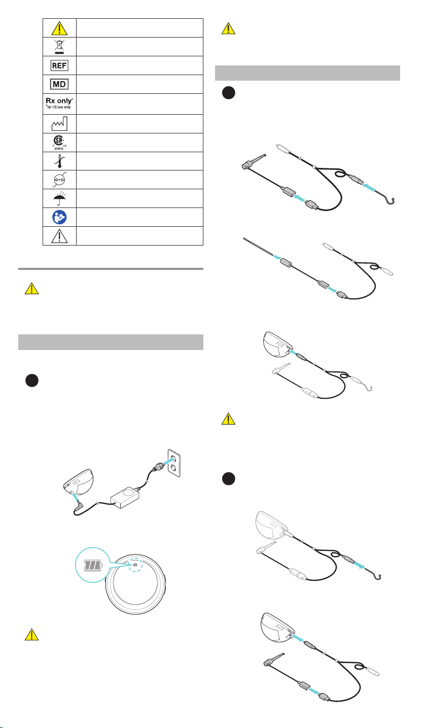
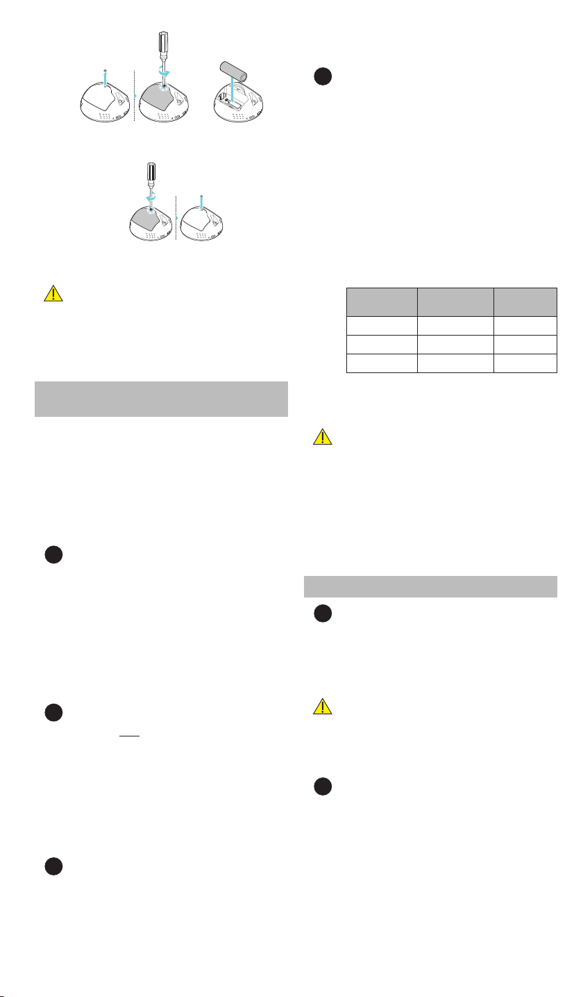
2. After removing the used battery, insert a new battery in the
correct direction of the battery terminal.
3. Place the battery cover on the back of the device, screw it in,
and insert the silicone ball into the screw hole.
PRECAUTIONS
• Dispose of used batteries in accordance with applicable laws
and regulations in the current country and region.
• Contact the dealer, Kerr Endodontics sales representative or Kerr
Customer Care and use an Apex Connect Battery approved by
Kerr Corporation.
CLEANING, DISINFECTION AND STERILIZATION
INSTRUCTIONS
After using the device, be sure to keep it thoroughly clean for the
next use. And clean everything thoroughly before autoclaving. In
order to prevent the dirt on the surface of the device from drying
out before cleaning, please wash it as soon as possible after use.
In addition, the reprocessing procedure should minimize delays
between steps.
Autoclavable Components: Lip hook, File
holder A and File holder B
The lip hook and the file holder must be sterilized after cleaning.
1Cleaning and Disinfection: File Holder A
1. Put the file holder A in the tap water for 5 minutes.
2. Thoroughly clean the surfaces of the file holder A with a
tissue containing isopropyl alcohol (e.g., CaviWipes).
•Wipe the surface of the file holder A at least twice in
one minute.
•Clean the surface of the file holder A thoroughly to avoid
leaving any residue of contamination.
3. Rinse the file holder A in tap water for at least 30 seconds.
4. Dry the file holder A with a soft cloth, and dry at room
temperature for at least 30 minutes.
2Cleaning and Disinfection: File Holder B
NOTE: Do not spray the File Holder B with a liquid
disinfectant.
1. Clean the surfaces of the file holder B with a tissue
containing isopropyl alcohol (e.g., CaviWipes).
• Wipe the surface of the file holder B at least twice in
one minute.
• Clean the surface of the file holder B thoroughly to avoid
leaving any residue of contamination.
2. Dry the file holder B with a soft cloth, and dry at room
temperature for at least 30 minutes.
3Cleaning and Disinfection: Lip Hook
1. Put the lip hook in the tap water for 5 minutes.
2. Thoroughly clean the surfaces of the lip hook with a tissue
containing isopropyl alcohol (e.g., Caviwipes).
• Wipe the surface of the lip hook at least twice in
one minute.
• Clean the surface of the lip hook thoroughly to avoid
leaving any residue of contamination.
3. Rinse the lip hook in tap water for 30 seconds.
4. Dry the lip hook with a soft cloth, and dry at room
temperature for at least 30 minutes.
4Packing and Sterilization
NOTE:
•Health Care facilities are responsible for making sure that
the sterilization equipment is calibrated according to the
manufacturer’s manuals and specifications. In addition,
health care facilities are responsible for training their staff
on infection control, proper sterilization and disinfection
procedures
•Make sure that the sterilization pouches are suitable for
steam sterilization and comply with the national guidelines,
standards, and requirements.
–ISO 11607
–For USA: Use FDA-cleared accessories
1. Place the cleaned lip hook and the file holder(s) into an
autoclave pouch.
2. Recommended sterilization parameters:
Cycle Gravity
Displacement
Pre-Vacuum
Temperature (°C) 121°C (250°F) 132°C (270°F)
Exposure time (min) 30 minutes 4 minutes
Drying time (min) 30 minutes 30 minutes
3. Take out the lip hook and the file holder from the autoclave
and dry it while keeping it packed in the pouch for at least
30 minutes at room temperature.
PRECAUTIONS
• Maximum number of re-sterilization of lip hook and the file
holder is 250 times.
• Immediately after sterilization, the lip hook and the file holder
can be very hot. Cool it sufficiently before use as there is a risk of
injury such as burns.
• Do not leave the lip hook and the file holder inside the
autoclave after sterilization.
• Never sterilize components other than the lip hook and the
file holder.
NONAUTOCLAVABLE COMPONENTS
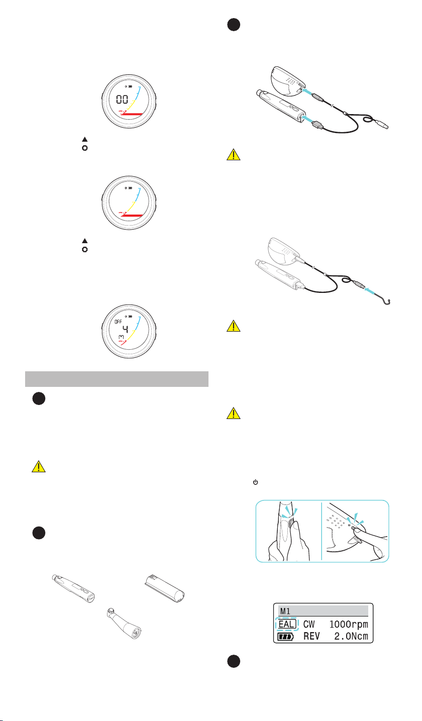
1Cleaning and Disinfection: Apex Connect Unit
After using the device, be sure to keep it clean for the next use.
•Wipe the surface of the Apex Connect Unit using a cloth
(or gauze) lightly moistened with ethanol (70-80%).
Clean the crevices with a cotton swab moistened with
ethanol. And dry at room temperature for 30 minutes.
PRECAUTIONS
• Do not use organic solvents such as thinner, benzene, or
methanol to clean the device.
• Do not put the device in alcohol or water and be careful not to
let foreign substances such as water or dust get inside the device.
2Cleaning and Disinfection: Probe Cord
1. Wet a small soft brush in ethanol for disinfection (ethanol
70-80 vol%) to remove all contaminants from the crevices
and all surfaces. (repeat 20 times)
2. Wipe all surface thoroughly using a cloth (or gauze) lightly
dampened in ethanol for disinfection. (repeat 20 times)
3. Wipe all surfaces with a cloth moistened with distilled
water, then dry with a clean, dry cloth.
4. After visual inspection to ensure cleanliness, repeat the
cleaning steps if contamination is visible.

910
STORAGE AND DISPOSAL
1Storage:
After sterilization, place the pouches containing the devices in a
dry and dark place such as a closed cupboard or a drawer.
•Follow the instructions provided by the pouch manufacturer
regarding storage conditions and maximum allowed time
in storage.
2Disposal
•For proper disposal always follow local and regional laws
(i.e. The Waste Electrical and Electronic Equipment - WEEE).
TROUBLESHOOTING GUIDE AND
TECHNICAL SUPPORT
If a problem occurs with the device, refer to the guide below. If
this guide does not resolve the problem, contact Customer Care
at 1-800-537-7123 (Available from 6:00am to 4:00pm PST).
Outside of these hours, email us at KerrCustCare@kavokerr.
com. Alternatively, contact the dealer or Kerr Endodontics sales
representative.
Problem Cause Solution
The power does
not turn on.
The battery
is dead.
Charge the battery before use.
If the problem persists, please
contact customer care
The Apex
Connect unit
is charging.
The Apex Connect Unit is
designed not to operate while
charging. Disconnect the
AC/DC Adapter from the device
and press the power button [ ].
The Apex
Connect Unit
turns off
during use.
The battery
is dead.
Charge the battery before use.
When
connecting the
File Holder B
or File Holder
Adapter, the
screen
automatically
turns off.
Either the File
Holder B or File
Holder Adapter
is faulty.
Switch off and restart the device
after replacing with the new File
Holder B or File Holder Adapter.
No alarm sounds. The alert sound
volume is set
to‘0’.
Refer to “User Environment
Settings”and adjust the
alarm volume.
The
measurements
are not displayed.
The probe cord
is not properly
connected.
Refer to “INITIAL SET-UP”and
install the probe cord.
Even though the
file has reached
the APEX, the
measured value
is not displayed.
The root canal is
completely dry.
Add saline solution to the
root canal.
Measurement
is not working
properly.
Foreign
substances such
as washing
liquid have
accumulated in
the mouth.
Measure after removing foreign
objects from the mouth.
There is a metal
restoration on
the tooth.
Make sure that the metal
restoration is not connected
to the root canal or the file, as
errors may occur if the metal
restoration is connected to the
root canal or contacts the file.
There is necrotic
dentin or tissue
and inorganic
debris in the
root canal.
If necrotic dentin and inorganic
debris in the root canal are not
removed, errors may occur, so
please start the measurement
with a thick file to a thin file.
This is a multi-
rooted canal
tooth.
Check with a radiograph if there
are any cracks in the teeth and
then re-measure
Problem Cause Solution
Er will flash
on the
measurement
screen.
Calibration
has not been
executed.
Disconnect the probe cord from
the Apex Connect Unit. Restart
the Apex Connect Unit and
reattach the probe cord to the
device. If problem persists, please
contact Kerr Customer Care.
SPECIFICATIONS
1General Specifications:
Item Description
Protection from electric shock Internal powered ME equipment
Degree of Protection (IEC 60529) IPX0
Applied part Lip hook, File holder A,
File holder B, File holder Adapter
Battery Lithium-ion battery
2Device specifications:
Item Description
Apex
Connect
Unit
Rated input 3.6 V / 1900 mAh (Lithium-ion
battery)
Dimensions 90 X 75.4 X 73.6 mm
Weight 184 g (including battery)
Operation mode Continuous operation
Accuracy ±0.5 mm
AC/DC
Adapter
Input voltage 100–240 V, 50–60 Hz
Output voltage 9 V DC
Output current 2.0 A
3Environmental Specifications:
Item Description
Operation Temperature 10–35°C (50–95°F)
Humidity 30–75%
Atmosphere pressure 700–1060 hPa
AC/DC Adapter Temperature -20–60°C (-4–140°F)
Humidity 5–90%
Atmosphere pressure 700–1060 hPa
WARRANTY
Kerr Endodontics warrants the system (excluding batteries) to
be free from defects in materials or workmanship for period
of 3 years from the original date of purchase.The batteries are
warrantied for a period of 6 months from the original date of
purchase.
If the system shows any defect within the warranty period that
are not excluded from this warranty, Kerr Endodontics shall, at its
sole discretion, either replace or repair the device using suitable
new or reconditioned parts. In the case other parts are used
which constitutes an improvement, Kerr Endodontics may, at its
discretion, charge the customer for the additional cost of these
parts. If the warranty claim provides to be justified, the product
will be returned to the user freight prepaid.Warranty claims
other than those indicated herein, are expressly excluded.
EXCLUSIONS
Damage and defects caused by the following conditions are not
covered by the warranty:
•Improper handling/disassembly/modifying, neglect,
or failure to operate the unit in compliance with the
instructions given in this manual.
•Force majeure or any other condition that is beyond the
control of Kerr Corporation.
•Damage caused by customer misuse or uses other than
those specified.

910
DISCLAIMER
For safety reasons, this product should be used with accessories
manufactured and sold by Kerr Corporation. Any use of non-
authorized accessories or not following any of the instructions
for use is done so at the operator’s risk and voids the warranty.
Kerr Corporation does not assume any responsibility for incorrect
diagnosis due to operator error or equipment malfunction.
Product name Apex Connect
Warranty Device: 3years / Accessories: 6 months
Manufacturer Distributed by:
Kerr Corporation
1889 W Mission Blvd., Pomona, CA 91766 USA
1-800-KERR-123 | kerrdental.com
Manufactured by:
Meta Systems Co., Ltd.
#1214-18, Sicox tower 12F, 484 Dunchon-daero,
Jungwon-gu, Seongnam-si, Gyeonggi-do, 13229,
Korea
PART NUMBERS
Part number Components
815-1802 Apex Connect Kit - US
815-1803 Apex Connect Kit - EU
815-1804 Elements/Apex Connect Power Cord - US
815-1805 Elements/Apex Connect Power Cord - EU
815-1807 Apex Connect AC/DC Adapter
815-1812 Apex Connect Probe Cord
815-1813 Apex Connect Lip Hook
815-1814 Apex Connect File Holder Adapter
815-1815 Apex Connect File Holder A
815-1816 Apex Connect File Holder B
815-1817 Apex Connect Replacement Battery
ELECTROMAGNETIC COMPATIBILITY
This device has been tested for compliance with electromagnetic
tests according to EN60601-1-2 and is designed to protect
against harmful interference when installing and using the
device following the instructions.This device can generate, use,
and discharge radio wave energy. This device may cause harmful
interference with other nearby equipment. In this case, the
user should use one or more of the recommendations described
below to resolve the interference.
•Increase the distance between the device and the device
causing the interference.
•Reinstall the device and restart.
•Contact the dealer, Kerr Endodontics sales representative or
Customer Care.
BUYER INFORMATION
Business Name _________________________________
Address ______________________________________
___________________________________________
Phone _______________________________________
Date of Manufacture ______________________________
Serial Number __________________________________
Date of Purchase_________________________________
Purchase Price/Quantity ____________________________
NOTES

Distributed by Kerr Corporation
1889 W. Mission Blvd.
Pomona, CA 91766 USA
1-800-KERR-123 | kerrdental.com
Manufactured by:
Meta Systems Co., Ltd.
#1214-18, Sicox tower 12F, 484
Dunchon-daero, Jungwon-gu
Seongnam-si, Gyeonggi-do
13229, Korea
Distribution Facility:
Kerr Australia Pty. Ltd.
12 Mars Rd., Unit 6
Lane Cove West
NSW, 2066 Australia
+61 2 8870 3000
MADE IN KOREA ML-43-001_Rev.A
2022-10
Table of contents
Other KERR ENDODONTICS Dental Equipment manuals