Kessil AP9X User manual

USER MANUAL
200327A1

TABLE OF CONTENT
01 INSIDE THE BOX, PARTS DIAGRAM
02 INSTALLATION & CONNECTION
03 TOUCH PANEL
04 WI-FI INDICATOR STATES
05 MODE INDICATOR STATES
06 MOUNTING, CONTROLLING MULTIPLE K-LINK & 0-10V
FIXTURES, WARNING
07 CONTROLLED BY SPECTRAL CONTROLLER X ,
TROUBLESHOOTING GUIDE, SPECIFICATIONS
08 DEEP CLEANING
09 SAFETY INSTRUCTIONS, INSTRUCTIONS DE SECURITE
10 MAINTENANCE, FCC STATEMENT
1
2
3
4
5
6
7
8
9
10
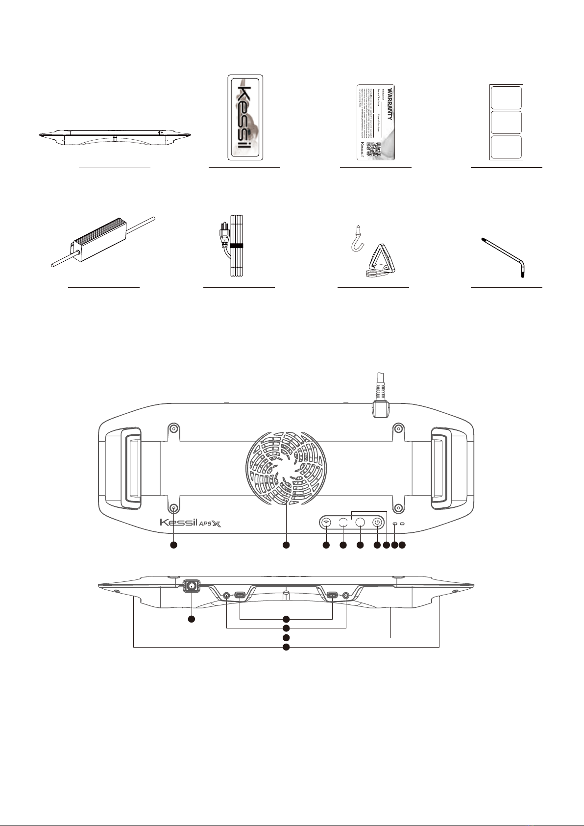
INSIDE THE BOX
AP9X
Power Adapter
Warranty Card
Kessil Sticker
Screw Hook &
Hanging Bracket x4
PARTS DIAGRAM
A Mode Indicator
B Wi-Fi Indicator
CTouch Panel - Touch once to activate
DPower - Turn the AP9X on or off.
EIntensity - Adjust the intensity of the light.
FColor - Adjust the color of the light.
GMode - Slave mode.
H Fan (Air Inlet)
I Screw Holes - For AP9X Mounting Arm
/ Hanging Kit / Brackets
J K-Link Ports
K0-10V Output Ports
L LED Arrays + Reflectors
MVents (Air Outlet)
N Power Cord
AC Adapter Cable
(Plug type varies from
country to country)
COLOR
1
INT
COLOR
Wi-Fi
Mode
K-Link0-10V(R) K-Link 0-10V(L)
C B ADEFGH
NL
L
K
I
M
J
QR Code Stickers
(This is for wireless
connection process, please
SAVE these stickers)
T10 M3 Torx key
(For deep cleaing)
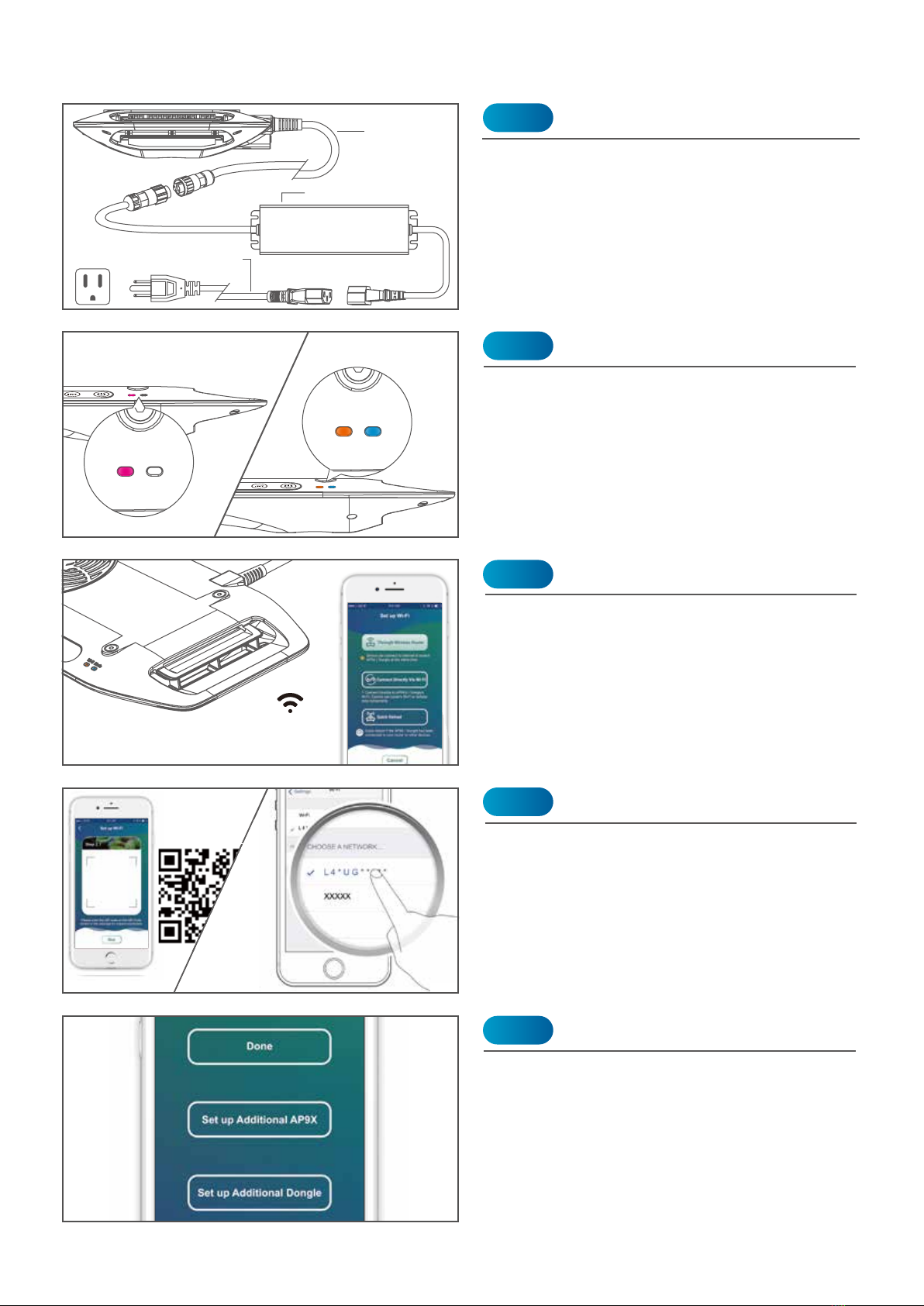
The AP9X requires 20-30 seconds to boot.
The Wi-Fi Indicator (B) will first show solid
purple light, and then turn to solid orange
light. The Mode Indicator (A) will also show
solid blue light.
* The light will be turned on automatically.
DO NOT place the AP9X on any object.
Connect the AP9X to the Power Adapter and
plug it into a wall outlet. The Wi-Fi Indicator
(B) will be solid purple to indicate booting
mode.
INSTALLATION & CONNECTION
Power
Booting
Step 1
Power Cord
(5.9ft / 1.8m)
Power Adapter
Step 2
If you have more AP9Xs, choose "Set up
Additional AP9X". Choose "Done" if you
complete the setup.
Set up More AP9X
Step 5
Adapter Cable (5.9ft / 1.8m)
(Plug type varies from country to country)
Download the “Kessil WiFi” app* in App Store
or Google Play Store.
* Only supports iOS 10.0 or above and Android 5.0
or above
Download “Kessil WiFi” App
Step 3
Open the “Kessil WiFi” app and follow the
instructions in the app to connect to AP9X.
You will need the QR Code Sticker provided
in the package. If you wish to enter the
password manually, the password is
reverse of the S/N of the AP9X (capital
letter matters).
Connection
Step 4
This is for wireless
connection process,
please SAVE these stickers.
***
Wi-Fi Mode
INT
Wi-Fi Mode
2
Wi-Fi Mode
INT
COLOR
Wi-Fi Mode
Booting After booting

Wi-Fi Mode
Wi-Fi Mode
TOUCH PANEL
Manual Control
COLOR : 9 color modes
INTENSITY : 5 intensity levels
Touch the Power (D) symbol to turn on/off the
AP9X.
Power ON: Mode Indicator (A) is solid blue
Power OFF: Mode Indicator (A) is solid red
Turn On/Off the AP9X
1% / 25% /50% /75%/100% Touch the Intensity (E) symbol and Color (F)
symbol to adjust the intensity and color of the
AP9X. Intensity levels and color modes are in
cycles.
Reset the AP9X Wi-Fi Configuration
Factory Reset the
AP9X
Wi-Fi Mode
INT
COLOR
Wi-Fi Mode
Wi-Fi Mode
INT
COLOR
Wi-Fi Mode
Touch and hold the Intensity (E) & Mode (G)
symbols simultaneously for 3 seconds to
reset the Wi-Fi configuration (i.e. to recon-
nect). The Wi-Fi Indicator (B) will turn solid
red. User's settings will not be deleted. The
Wi-Fi Indicator (B) will change to solid
orange after booting.
Touch and hold the Intensity (E), Color (F) &
Mode (G) symbols simultaneously for more
than 5 seconds to reset the AP9X. The Wi-Fi
Indicator (B) will blink red. Replug the power
plug within 30 seconds. User's settings will
be deleted. The Wi-Fi Indicator (B) will
change to solid orange; Mode Indicator (A)
will change to solid blue after booting.
3
Touch the Touch Panel (C) once to activate
4
Booting
Wi-Fi ON
Wi-Fi OFF
Standby /
No Connection
Connected
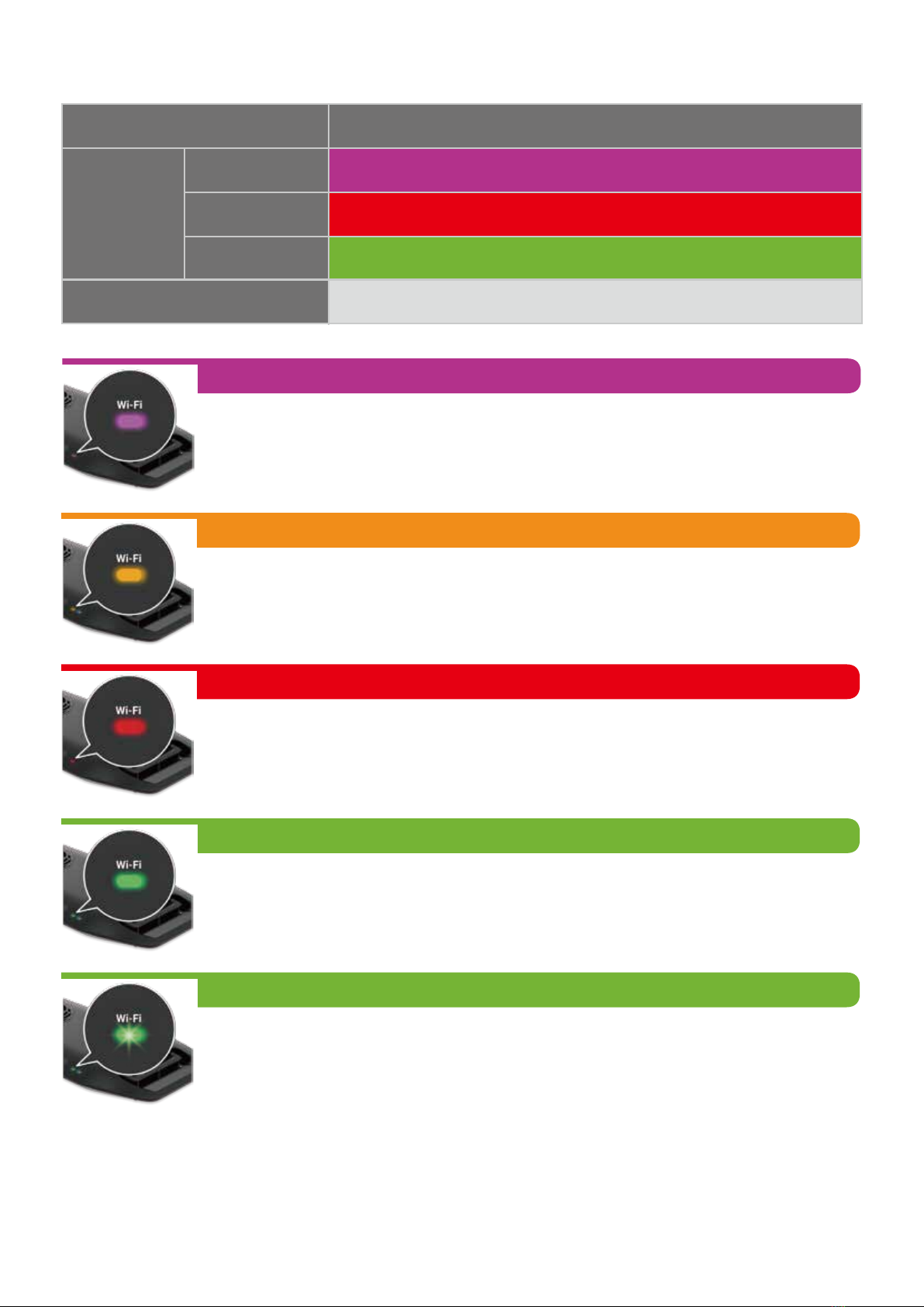
Solid Purple
Wi-Fi_STA Mode
Solid Red
Solid Green
(To connect to a wireless router or master Kessil Wi-Fi enabled products)
No Light
Solid Orange
Standby mode, ready to be connected.
Solid Purple
The AP9X requires 20-30 seconds to boot. The AP9X Wi-Fi Indicator (B) will
show solid purple light.
Solid Red
Attempting to connect. If it stays for more than 3 minutes, reset AP9X's WiFi
configuration (Touch and hold the Intensity (E) & Mode (G) symbols simulta-
neously for 3 seconds) and add the AP9X in the app again.
Blinking Green
When updating the AP9X’s firmware through Kessil WiFi app, the Wi-Fi Indi-
cator (B) will blink green light.
Solid Green
STA mode. Successfully connected to wireless router or to a master Kessil
Wi-Fi enabled product as slave.
WI-FI INDICATOR STATES
Solid Orange
Solid Orange
NOT broadcasting Wi-Fi signal. K-Link signal as Input, able to daisy-chain
other master & slave AP9X.
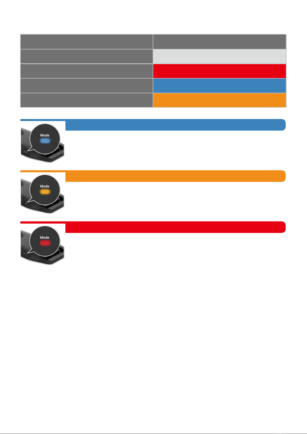
Solid Red
Power is at OFF mode.
Solid Blue
Broadcasting Wi-Fi signal. K-Link signal as Output , able to daisy-chain other
slave AP9X (Unable to daisy-chain other master AP9X).
MODE INDICATOR STATES
5
Booting
Power OFF
K-Link as Output
K-Link as Input
Solid Purple
Mode
Solid Red
Solid Blue
No Light

WARNING
CONTROLLING MULTIPLE K-LINK & 0-10V FIXTURES
MOUNTING
• Hang the light with the four Screw Hooks and the four Hanging Brackets.
• To install the Hanging Brackets, remove the screws on the AP9X, use the same screws
to secure the fasteners with triangular rings (Hanging Brackets) onto the light fixture.
6
0-10V(Output only) 0-10V(Output only)K-LinkK-Link
K-Link0-10V(R) K-Link 0-10V(L)
Master: Controllable
touch panel (C)
Slave: Touch panel (C)
cannot be controlled
When multiple X-series K-Link fixtures are daisy-chained, the Touch Panel (C) of the slave
fixture(s) is deactivated. Control is only available on the master fixture.
INT
COLOR
Wi-Fi Mode
INT
COLOR
Wi-Fi Mode
• Two K-Link ports (J): Connect and control multiple X-series K-Link fixtures using "Kessil
WiFi" app and K-Link Cables. When connecting Kessil Wi-Fi enabled products, make
sure to switch them to slave mode. When controlling them manually, tuning controls on
any light control all other lights in chain.
• Two 0-10V Output ports (K): Connect and control multiple 0-10V fixtures by using
"Kessil WiFi" app.
INT
COLOR
Wi-Fi Mode
INT
COLOR
Wi-Fi Mode

Dimensions
Weight
16.46” x 5.71” x 1.42” (418mm x 145mm x 36mm)
2.05 Ibs (0.93 kg)
llluminator Power Adapter
Power Consumption 185W maximum Input 100-240V~ AC 50-60 Hz
Input Voltage 48V DC 5% Output 48V DC, maximum 4.2A
+
_
SPECIFICATIONS
Size and Weight
Operating Frequency IEEE 802.11b/g/n(2.4GHz) & IEEE 802.11a/ac(5GHz)
Network Encryption Type
Wi-Fi Module
WPA-PSK / WPA2-PSK
(Do not support WEP, WPA-Enterprise, WPA2-Enterprise, and Monitor Mode.)
CONTROLLED BY SPECTRAL CONTROLLER X
- AP9X can be connected and controlled through Kessil Spectral Controller X with a
K-Link Cable.
- Switch the AP9X to slave mode first, by touching the Mode (G) symbol for 3 seconds,
then connect to the Spectral Controller X. The AP9X will be grouped under the TB group.
INT
COLOR
Wi-Fi Mode
INT
COLOR
Wi-Fi Mode
TROUBLESHOOTING GUIDE
Problem
Make sure the fan is operating properly.
Cause / Solution
Please make sure to perform maintenance before doing any troubeshooting.
Light doesn’t turn ON
Unit is flickering
Make sure the unit is connected to the power adapter and the power adapter is plugged
into an outlet with the correct specifications.
Make sure the device is operating within the specified operating temperature range. If
unit overheats, it will automatically shut down.
Make sure the unit has not overheated by operating at a room temperature above
100°F/40°C.
Make sure the power adapter has the right specifications.
Make sure the power adapter has the right specifications.
Make sure electrical power is available to the AC outlet being used.
7
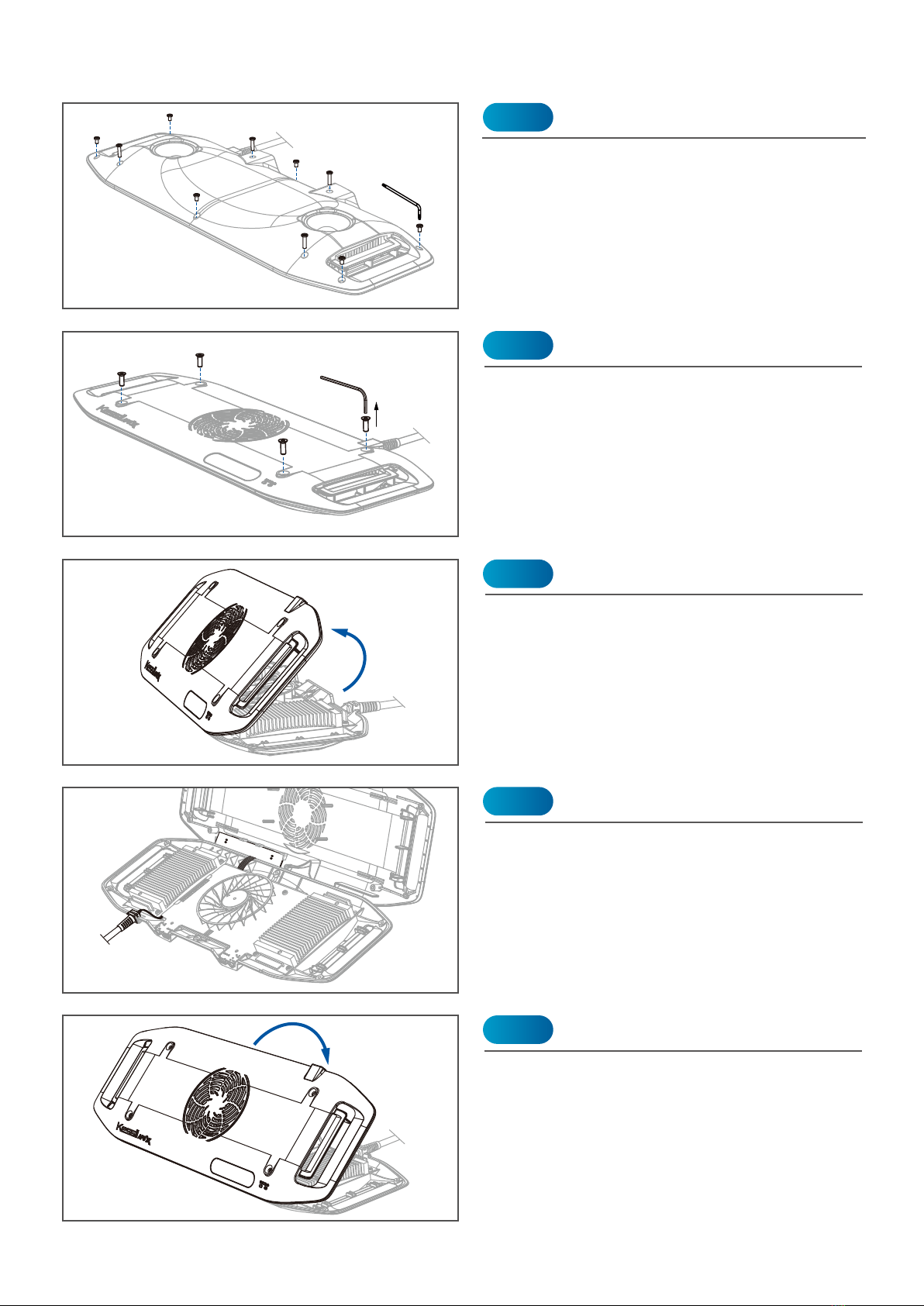
DEEP CLEANING
Use a 2.5mm Hex key (Not included) to
remove 4 (L: 12mm) M4 screws (I) on the
upper cover.
Use a T10 Torx key to remove 10 (4 x L:
12mm / 6 x L: 5mm) M3 screws on the bottom
cover.
Remove the Screws on the Bottom
Remove the Screws on the Top
Step 1
Step 2
Ensure the Touch panel cable and the Power
Cord (N) are properly placed. Flip the cover
back and screw in all the screws on the top
and bottom covers.
DO NOT over-tighten the screws to avoid
parts damage.
Reassemble
Step 5
Carefully flip the cover from the rear side.
HANDLE WITH CARE: DO NOT pull the
Touch Panel cable
Flip the Cover
Step 3
Clean and remove any dust and debris using
a CO2 dust blower (or similar dust blower) or
an alcohol wipe. Do not remove other screws
to avoid parts damage.
Cleaning
Step 4
8

1. Attention: Une mauvaise utilisation de cet appareil contrairement à ces instructions peut
entraîner des blessures ou endommager le produit.
2. N'UTILISEZ PAS d'adaptateur secteur en dehors des spécifications. Il s'agit d'un risque
d'incendie et peut entraîner une panne de l'unité.
3. NE PAS utiliser à l'extérieur. Cet appareil est destiné à une utilisation en intérieur uniquement.
4. N'exposez PAS l'appareil à un environnement extrêmement humide et ne l'immergez pas dans
l'eau. Cela peut entraîner une panne de l'unité.
5. NE placez PAS l'illuminateur de travail en contact étroit avec des objets. Cela peut provoquer
une surchauffe des objets et une surchauffe de l'appareil.
6. Gardez la matrices LED + le réflecteurs (L) loin des objets pointus. Des objets tranchants
peuvent briser la lentille du réseau et entraîner une défaillance de l'unité.
7. NE PAS couvrir ni placer d'objets sur l'adaptateur secteur. L'adaptateur secteur ne doit pas être
contenu dans un espace hermétique.
8. NE PAS bloquer ou couvrir le ventilateur (entrée d'air) (H) ou l'évent (sortie d'air) (M). Cela peut
entraîner une surchauffe de l'appareil et entraîner une panne.
9. ASSUREZ-VOUS que la lumière est correcte et solidement montée.
INSTRUCTIONS DE SECURITE
SAFETY INSTRUCTIONS
1. Caution: Misuse of this device contrary to these instructions may result in physical injury or
damage to the product.
2. DO NOT use a power adapter outside of the specifications. This is a fire hazard and may lead
to unit failure.
3. DO NOT use outdoors. This unit is intended for indoor use only.
4. DO NOT expose unit to an extremely humid environment or submerse unit in water. This may
lead to unit failure.
5. DO NOT place working illuminator in close contact with any objects. This may cause objects to
heat up and the unit to overheat.
6. KEEP LED Arrays + Reflectors (L) away from sharp objects. Sharp objects may break the array
lens and lead to unit failure.
7. DO NOT cover or place objects on the power adapter. Power adapter should not be contained
in an airtight space.
8. DO NOT block or cover the Fan (Air Inlet) (H) or Vent (Air Outlet) (M). This may cause the
device to overheat and lead to failure.
9. ENSURE that the light is correct and securely mounted.
9

FCC STATEMENT
This device complies with Part 15 of the FCC Rules. Operation is subject to the following two
conditions: (1) This device may not cause harmful interference, and (2) this device must accept any
interference received, including interference that may cause undesired operation.
This equipment has been tested and found to comply with the limits for a Class B digital device,
pursuant to Part 15 of the FCC Rules. These limits are designed to provide reasonable protection
against harmful interference in a residential installation. This equipment generates, uses and can
radiate radio frequency energy and, if not installed and used in accordance with the instructions,
may cause harmful interference to radio communications. However, there is no guarantee that
interference will not occur in a particular installation. If this equipment does cause harmful
interference to radio or television reception, which can be determined by turning the equipment off
and on, the user is encouraged to try to correct the interference by one of the following measures:
• Reorient or relocate the receiving antenna.
• Increase the separation between the equipment and receiver.
• Connect the equipment into an outlet on a circuit different from thatto which the receiver is
connected.
• Consult the dealer or an experienced radio/TV technician for help.
FCC Caution:
• Any changes or modifications not expressly approved by the party responsible for compliance
could void the user's
authority to operate this equipment.
• This transmitter must not be co-located or operating in conjunction with any other antenna or
transmitter.
Radiation Exposure Statement:
This equipment complies with FCC radiation exposure limits set forth for an uncontrolled
environment. This equipment should be installed and operated with minimum distance of 8 inches
(20cm) between the radiator & your body.
MAINTENANCE
1. Keep the Fan (Air Inlet) (H) and Vents (Air Outlet) (M) clear of dust. To clean the fan,
unplug the unit and insert the tip of a CO2 dust blower (or similar dust blower) in one
of the venting holes for the Fan (Air Inlet) (H). Hold and spray. You can also gently
vacuum out the dusts through the venting holes.
2. Keep the LED Arrays + Reflectors (L) clean. If the array lenses and reflectors become
contaminated with water, dust, or other particles, unplug the unit and clean them with
isopropyl alcohol. Wet a cotton swab or a napkin in isopropyl alcohol, gently wipe the
surface, and let it dry.
3. Keep plastic covers for K-Link Ports (J) and 0-10V Output Ports (K) plugged in when
the ports are not in use. Keep the ports clean all-time.
10
@kessilled
@kessil kessil.comkessil.led kessiltube
Other manuals for AP9X
1
Table of contents
Other Kessil Aquarium manuals


Popular Aquarium manuals by other brands


TMC
TMC Next Wave Tank 60 instructions

Dupla MARIN
Dupla MARIN Makro Resort MR 800 Operating instruction

JBL
JBL NitratEx Directions for use

Red Sea
Red Sea REEFER-S 850 G2 Assembly manual

D-D The Aquarium Solution
D-D The Aquarium Solution Kamoer FX-STP WIFI user manual

Red Sea
Red Sea Reefer XXL 750-V3 Assembly manual


