Troubleshooting
Ketra’s LS0 linear should power on to a default white state. If it powers on to some other color, that means there’s a
problem in the installation conditions. See the table below for the meaning of each color.
TROUBLESHOOTING TABLE
Color Condition Correction
Red or OFF Voltage from X96 Controller is
too low
Ensure that the controller is the Ketra X96
controller. Check to see if total cable length
exceeds 50 ft (15 m), reduce to 50 ft (15 m) of cable
from X96 to last LS0 segment. Ensure that power
conductors are 16 AWG or 12 AWG (1.5 mm2or
3.5 mm2) wires, or use the QSHCBL(P)-M500
or QSHCBL(P)-L500. Ensure that length of
LS0 linear does not exceed maximum length
requirements i.e., 15 ft (4.5 m) for high output and
24 ft (7.3 m) for long run. Verify power connections
(red and black on QSHCBLM500) are wired
correctly on the X96 controller and each luminaire
adapter
Magenta LS0 is installed backwards Disconnect power, check wiring at adapters and
follow wiring directions above, or disconnect
luminaire and reverse direction
Blue Missing or reversed
communication signals
Verify communication (purple and white on
QSHCBLM500) are wired correctly on the X96
controller and each luminaire adapter
Green or OFF Line voltage is too low Line voltage must be nominally 120 or 277 V~
60 Hz for X96
Yellow Number of luminaires exceeds
length limits. Limit for 15 ft
(4.5 m) for high output and
diused lens type and 24 ft
(7.3 m) for long run lens type.
Remove excess luminaires and power cycle the X96
controller
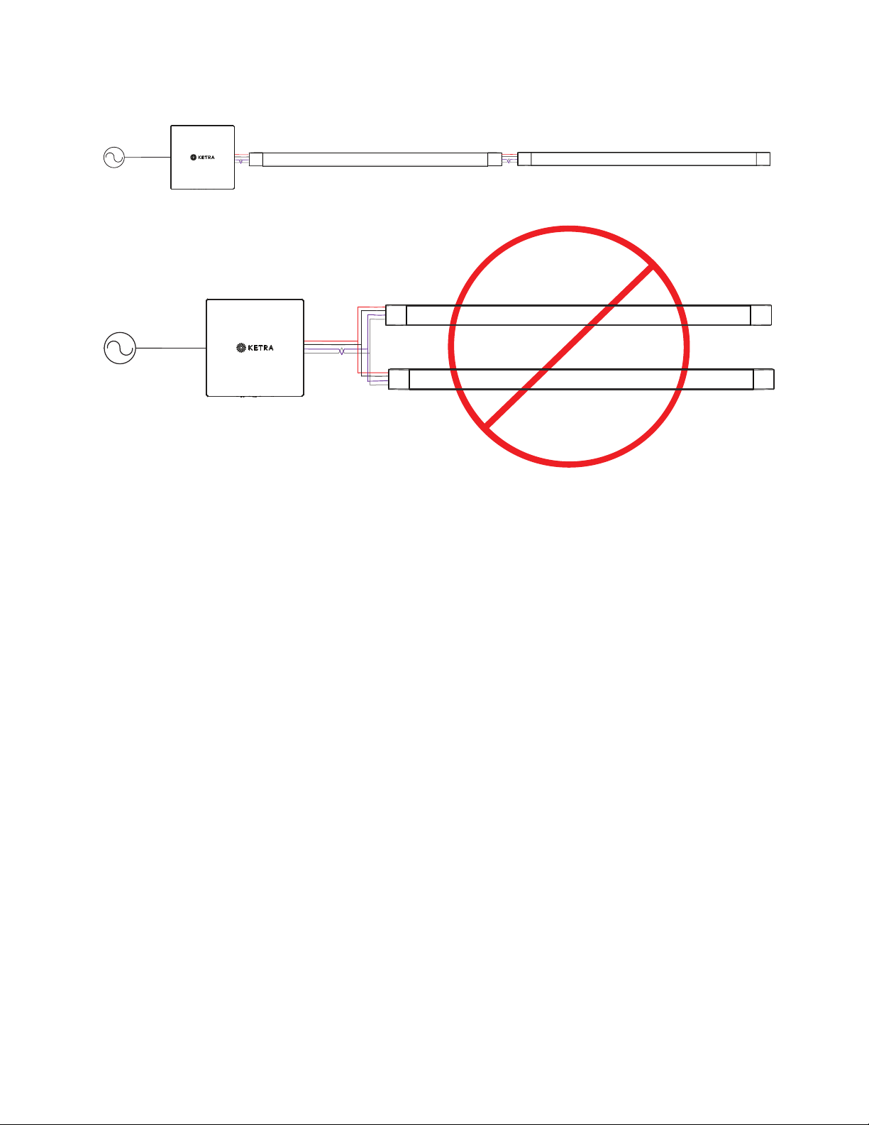
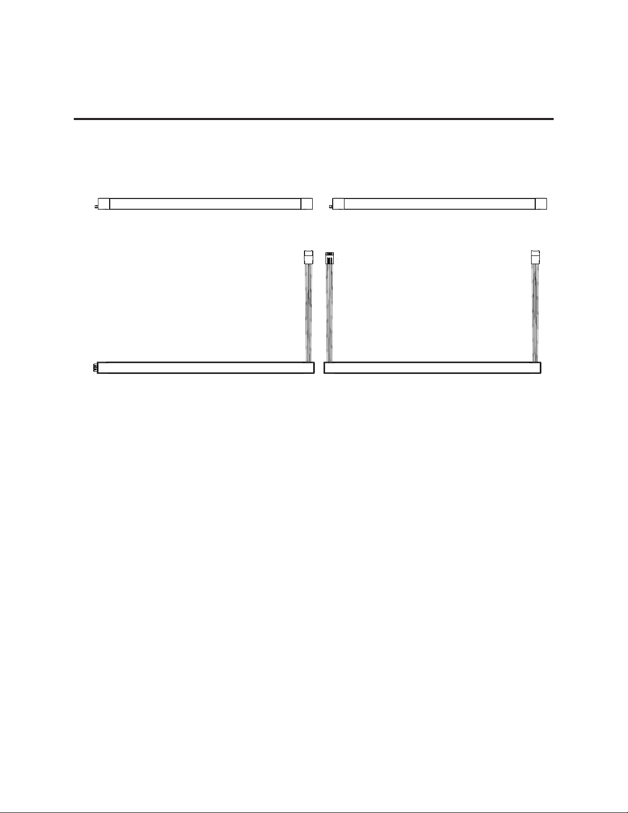
Example System Connection
10|LS0 INSTALLATION GUIDE
P/N 3662562 Rev A
© 2021 Lutron Electronics Co., Inc. All rights reserved.