PAGE 5N3 INSTALLATION INSTRUCTIONS 770-000014-01-01
CONTENTS
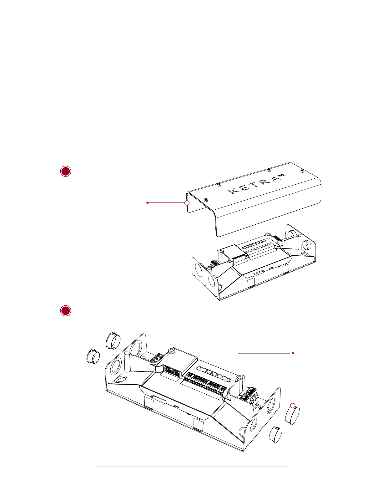
N3 SATELLITE UNIT
SPECIFICATIONS
Performance Summary
•Enables Ketra’s luminaires to join the Ketra control network
•Wireless network for easy installation
•On-board content storage and astronomical time clock
•Multiple control inputs and outputs for integration of
third-party control and lighting products
•Compatible with standard occupancy and daylight sensors
N3 Satellite
Project:
Comments:
Prepared By:
© 2014 Ketra. Inc. All rights reserved.Designed in Austin, Texas +1.512.347.1100 |www.goketra.com
PRODUCT SPECIFICATIONS
N31INDBK
Ordering Code:
Enclosure + Connections
Connections (Class 1)
AC Power In (3 Line 120V) 10-16AWG (Line Neutral, Ground)
AC Power Out (4 Line ) Standard Ketra Leader Cable or
10-16 AWG
Connections (Class 2)
Multifunction I/O 16-24 AWG
0-10V Input/Output
Contact Closure Input/Output
0-24V Input
DMX
KetraNet LinkTM
KetraNet MeshTM Wireless
USB Port 1 - Micro-B USB console port,
for fi rmware updates
770-000005-01-13
Specifi cations are subject to change without notice.
Mechanical
Weight 2.93 lbs, 1.33 kg
Housing Material Formed steel, Polymer
Environmental
Operating Temperature -20° to 50°C
Storage Temperature -20° to 80°C
Humidity 0 - 95%, Non-condensing
Certifi cation UL, cUL, FCC Class A, RoHS
Location UL Damp Location, IP20
Power
Load Ratings
Per Unit: 16Amps @ 120 VAC, 60 Hz (20 Amps de-rated to 80%)
Power Requirements
Unit consumes 5W electrical power
To compute total load, add 5W to sum of all connected luminaire power
ratings.
5.13”, 130.3mm
0.75”,
19mm
2.38”
60.5mm
2.76”
70mm
11.05”, 280.7mm
0.2”, 4.5mm Ø
Clearace Fit for No.9 Drywall Screw
9.97”, 253.3mm
1.0”,
25mm
0.2”
5mm
5.13”, 130.3mm
0.75”,
19mm
2.38”
60.5mm
2.76”
70mm
11.05”, 280.7mm
0.2”, 4.5mm Ø
Clearace Fit for No.9 Drywall Screw
9.97”, 253.3mm
1.0”,
25mm
0.2”
5mm
5.13”, 130.3mm
0.75”,
19mm
2.38”
60.5mm
2.76”
70mm
11.05”, 280.7mm
0.2”, 4.5mm Ø
Clearace Fit for No.9 Drywall Screw
9.97”, 253.3mm
1.0”,
25mm
0.2”
5mm
Performance Summary
•Enables Ketra’s luminaires to join the Ketra control network
•Wireless network for easy installation
•On-board content storage and astronomical time clock
•Multiple control inputs and outputs for integration of
third-party control and lighting products
•Compatible with standard occupancy and daylight sensors
N3 Satellite
Project:
Comments:
Prepared By:
© 2014 Ketra. Inc. All rights reserved.Designed in Austin, Texas +1.512.347.1100 |www.goketra.com
PRODUCT SPECIFICATIONS
N31INDBK
Ordering Code:
Enclosure + Connections
Connections (Class 1)
AC Power In (3 Line 120V) 10-16AWG (Line Neutral, Ground)
AC Power Out (4 Line ) Standard Ketra Leader Cable or
10-16 AWG
Connections (Class 2)
Multifunction I/O 16-24 AWG
0-10V Input/Output
Contact Closure Input/Output
0-24V Input
DMX
KetraNet LinkTM
KetraNet MeshTM Wireless
USB Port 1 - Micro-B USB console port,
for fi rmware updates
770-000005-01-13
Specifi cations are subject to change without notice.
Mechanical
Weight 2.93 lbs, 1.33 kg
Housing Material Formed steel, Polymer
Environmental
Operating Temperature -20° to 50°C
Storage Temperature -20° to 80°C
Humidity 0 - 95%, Non-condensing
Certifi cation UL, cUL, FCC Class A, RoHS
Location UL Damp Location, IP20
Power
Load Ratings
Per Unit: 16Amps @ 120 VAC, 60 Hz (20 Amps de-rated to 80%)
Power Requirements
Unit consumes 5W electrical power
To compute total load, add 5W to sum of all connected luminaire power
ratings.