THE KETT TOOL COMPANY 5055 Madison Road, Cincinnati, Ohio 45227
(513) 271-0333 fax (513) 271-5318 www.kett-tool.com
INSTRUCTIONS FOR THE CARE OF
THE KETT 41-20 SHEAR HEAD
CAUTION
Disconnect Power Unit
Before Servicing Tool
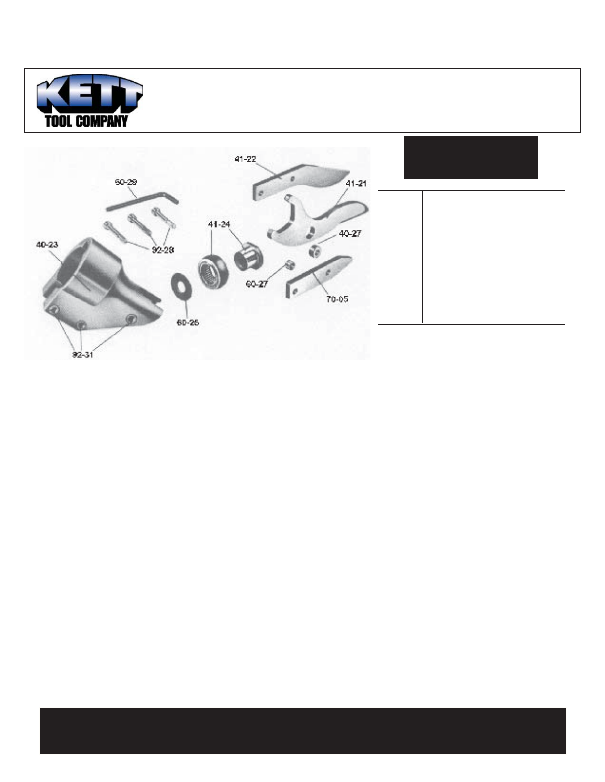
PARTS LIST
41-21 Center Blade
40-23 Shear Housing
41-24 Eccentric Bearing Assembly
40-27 Spacer Bushing
92-28 Cap Screw (3)
92-31 Knurled Insert (3)
41-22 Side Knife
70-05 Side Spacer
60-25 Thin Washer, Large
60-27 Spacer Bushing
60-29 (150-4) Allen Wrench
DISASSEMBLY: To remove the shear head from the
motor loosen three cap screws (92-28). Remove shear
head from motor by pulling head firmly forward. Slight
tapping with a mallet may be required if head does not
slide off easily.
To remove cutter blades from shear head remove
three cap screws (92-28) from shear housing (40-23).
Be careful not to lose rear spacer bushing (60-27) when
removing the middle cap screw. Remove center blade
(41-21) from shear housing by tapping blade gently rear-
ward. Be careful not to lose spacer bushing (40-27) from
hole in center blade. Side knife (41-22) and side spacer
(70-05) will now drop out of the shear housing.
To remove eccentric bearing assembly (41-24)
from shaft use an appropriate wrench to loosen eccen-
tric nut by turning counter clockwise.
ASSEMBLY: To install eccentric bearing assembly (41-
24) onto shaft, make sure the large thin washer (60-25)
is first inserted over the shaft. Screw eccentric bear-
ing assembly on to shaft and tighten with appropriate
wrench. Lubricate bearing with a good grade of bearing
grease.
To install cutter blades into shear housing (40-
23) place the side knife (41-22) and side side spacer
(70-05) into position in the shear housing (40-23). Insert
center cap screw (92-28) through the 41-21 and 70-05
with rear spacer bushing (60-27) between them and
start cap screw into thread just enough to hold blades in
place. DO NOT TIGHTEN. Insert spacer bushing (40-
27) into hole in center blade (41-21) and lubricate with
Molybdenum Disulfide grease (264-2) or equivalent.
Install center blade into shear housing by tapping blade
gently forward using a drift to line up hole in center blade
with forward holes in housing. Insert and tighten forward
cap screw (92-28) making sure spacer bushing (40-27)
in center blade stays in position. Apply Molybdenum
Disulfide grease (264-2) or equivalent to clevis or yoke
in center blade where it rides on the eccentric bearing
assembly. Insert rear cap screw (92-28) into shear hous-
ing, but do not completely tighten.
To install shear head assembly onto drive motor
make sure all cap screws (92-28) are loosened about
three or four complete turns. Spread shear housing
(40-23) slightly using a spreader (drift) near the rear cap
screw (92-28). Place shear head onto unit, tap side knife
rearward as far as it will go, and tighten cap screws to
40-45 inch pounds. It may be necessary to gently tap
the shear head into place if it does not readily slip onto
the nose of the power unit.
WARNING: THE KETT TOOL CO. CANNOT ASSUME RESPONSIBLITY FOR DAMAGE TO OR
MALFUNCTION OF A KETT SHEAR HEAD USED IN COMBINATION WITH ANY DRILL OTHER
THAN THOSE REGULARLY SUPPLIED BY US.
40-61 Not Shown
Adapter (1 3/8”-20 LH thread) fits
253-58 power unit on KD-441 power
shear.