Kett SHN User manual

I
N
S
T
R
U
C
T
I
O
N
M
A
N
U
A
L
MADE IN U.S.A.
SUPER
MODEL
SHN
NIBBLER
SUPER HEAVY DUTY 3/8" CAPACITY
KETT TOOL COMPANY 5055 MADISON ROAD CINCINNATI, OHIO 45227-1494
513/271-0333
FAX 513/271-5318

KETT / Fenway Super Nibbler 2
K
E
T
T
S
U
P
E
R
N
I
B
B
L
E
R
1. CAUTION: Always disconnect power cord before attempting adjustment or maintenance.
2. Shim stripper to 1/16 inch above metal thickness being cut. See table "A", (Figure 4.)
3. Tighten all screws and check punch and die clearance at least once daily.
4. Keep punch and die sharp and a spare in stock.
5. Turn nibbler on before engaging material.
6. When possible, spread a thin film of oil on surfaces being cut as this will greatly extend punch and die life.
7. Alwaysstopmachineimmediatelyifitshouldjam. Neverforcetool. Unplugtool.Backoutpunchbyinserting
screwdriver in operating slot at rear of motor and turning motor shaft counter clockwise.
8. Always let nibbler do the work as guiding tool is all that is necessary and forcing will only cause it to operate
improperly.
9. Only cut the gauge metal that is recommended or servicing and expensive part damage will occur.
10. Always observe lubrication instructions.
11 Always make frequent checks on motor brushes, replacing if worn.
12. Your KETT / FENWAY model "SUPER" motor body is provided with four 5/16 -18 tapped holes on a 3 inch
square bolt pattern. When bench mounted, your "SUPER" Nibbler becomes a handy tool for shaping small
metal parts up to 3/8 inch thick, which may be fed into punch by hand with ease.
SPECIFICATIONS
MAXIMUM MATERIAL THICKNESS (CUTTING CAPACITY)
MILD STEEL 3/8" (.375 in. / 9.53 mm.)
STAINLESS STEEL 1/4" (.250 in. / 6.35 mm.)
NON-FERROUS 7/16" (.437 in. / 11.11 mm.)
MAXIMUM CUTTING SPEED
35 INCHES PER MINUTE (.9 meters per minute.)
MINIMUM CUTTING RADIUS*
12 inches (304.8 mm.)
(* Primarily designed for straight cutting.)
PHYSICAL SIZE
15" (38 mm) Long, 6"(148 mm) wide
HEIGHT
11-1/2 inches (290 mm)
WEIGHT
40 lbs
. (88 Kgs.)
MOTOR
4-1/2 H.P. (3300 watts), 110 volts* 20 Amp
(*Available in 220 v at additional charge.)
STARTING HOLE SIZE
3 inches (74 mm) in diameter
SIZE OF CUT
3/8" (9.53 mm) x 1/4" (6.35 mm)
IMPORTANT OPERATING HINTS
(2

S
A
F
E
T
Y
I
N
S
T
R
U
C
T
I
O
N
S
F
O
R
P
O
R
T
A
B
L
E
E
L
E
C
T
R
I
C
T
O
O
L
S
KETT / Fenway Super Nibbler 3
REPLACEMENT PARTS
:
When servicing, use only original KETT / FENWAY replacement parts.
1.
DISCONNECT TOOLS
When not in use; before servicing, when changing accessories such as punch, die, brushes, etc.
2.
KEEP WORK AREA CLEAN
Cluttered areas and benches invite accidents.
3.
AVOID DANGEROUS ENVIRONMENT
Keep work area well lit. Do not use in a wet or damp environment.
4.
KEEP CHILDREN AWAY
All visitors should be kept a safe distance from work area.
5.
STORE IDLE TOOLS WHEN NOT IN USE
Tools should be stored in a dry, high, or locked-up place out of the reach of children.
6.
DON’T FORCE TOOL
It will do the job better and safer at the rate for which it was designed.
7.
USE RIGHT TOOL
Don’t force small tool or attachment to do the job of heavy-duty tool.
8.
WEAR PROPER APPAREL
No loose clothing or jewelry to get caught in moving parts.
9.
USE SAFETY GLASSES
Use safety glasses with all tools. Also face or dust mask if cutting operation is dusty.
10.
DON’T ABUSE CORD
Never carry tool by cord or yank it to disconnect from receptacle. Keep cord from heat, oil, and sharp edges.
11.
SECURE WORK
Use clamps or vise to hold work. It’s safer than using your hand and it frees both hands to operate tool.
12.
DON’T OVERREACH
Keep proper footing and balance at all times.
13.
MAINTAIN TOOLS WITH CARE
Keep tools sharp and clean for best and safest performance. Follow operating instructions for adjustments,
lubricating and changing accessories.
14.
REMOVE ADJUSTING KEYS AND WRENCHES
Form habit of checking to see that keys and adjusting wrenches are removed from tool before turning it on.
15.
AVOID ACCIDENTAL STARTING
-
Don’t carry plugged in tool with finger on switch. Be sure switch is off when plugging in.
16.
OUTDOOR USE EXTENSION CORDS
-
When tool is used outdoors, use only extension cords marked "suitable for use with outdoor appliances."
Store indoors when not in use.
SERVICING INSTRUCTIONS:
All repairs and maintenance of the electrical components, armature, field, switches and cords of either double insulated
or grounded tools must be performed by an authorized service center.
FOR ALL TOOLS - GROUNDED AND DOUBLE INSULATED

ACCESSORIES
Item No. Part No. Qty. DESCRIPTION
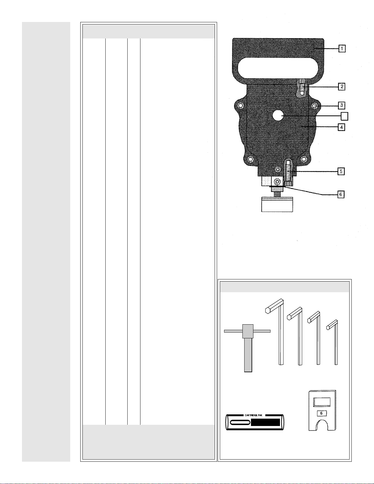
1 N7065 1 Handle
2 N7018 4 Screw, Handle
3 N7057 4 Screw, Body
4 N7037 1 Nose Housing
5 N7055 4 Screw, Die Holder
6 N7035 4 Stripper Shim
10 N7040 2 Bearing, Eccentric Shaft
11 N7038 1 Eccentric Shaft
12 N7039 1 Slider Block
13 N7036 1 Plunger
15 N5027 1 Screw, Punch Locking
16 N7032 1 Stripper Clamp Plate
17 N7031 1 Screw, Stripper
18 N7030 1 Stripper
N7030-1 1 Stripper, SHN-II
19 N7033 1 Punch
N7034 1 Punch, HSS
20 N7028 1 Die
N7029 1 Die, HSS
21 N7063 1 Die Holder
22 N7052 1 Pinion Gear Shaft
23 N7051 1 Small Gear
24 N5054 2 Bearing
25 N7046 1 Eccentric Shaft Spacer
26 N7041 1 Large Gear
27 N7045 1 Key
28 N7049 1 Screw, Ground
29 N3006 1 Ground Wire Assy.
30 N3007 1 Ground Wire Retainer
31 N3008 2 Screw, Switch Mounting
32 1 Switch
33 N3011 1 Screw, Ground
34 N3012 2 Screw, Cord Clamp
35 N3013 1 Cord Clamp
36 N3014 1 Strain Relief
37 N3002 1 Handle
38 N3003 1 Handle Cover
39 N3004 5 Handle Cover Screw
40 N3017 2 Handle Locking Screw
41 N3016 2 Self Lock Nut for Handle
42 N7015 1 Cord With Plug
43 N7001 1 Motor Housing*
AN7001 1 Complete Motor Housing Assy.**
44 N7058 2 Die Screw
45 N3050 2 Lock Washer
46 N7054 2 Dowel Pin
47 N7042 1 Gear Housing
48 N5024 1 Load Spring
49 N7048 1 Front Armature Bearing
50 N7068 1 Fan
51 N7047 2 Field Screw
52 N2050 2 Lock Washer
53 N7019 1 Motor Field (110V)
N7020 1 Motor Field, 220V
54 N7021 1 Armature (110V)
N7022 1 Armature, 220V
55 N5032 2 Brush Holder Cap
56 N7026 2 Brush Holder(not replaceable)
57 N5071 2 Field Spring
58 N3048 1 Rear Armature Bearing
59 N7044 2 Carbon Brush
60 N3059 1 Button Plug
S
U
P
E
R
P
A
R
T
S
L
I
S
T
KETT / Fenway Super Nibbler 4
PARTS LIST
* Includes: N7026
** Includes: N7001, N3002, N3003, N3004, N3016, N3017,
N3012, N3013, N5032, N7026
Figure 1
CARTRIDGE PAK
KETT
LUBRICANT
(1//4) (3/16) (5/32) (3/32)
N7059 N0106 N0105 N0102 N0101
"T" WRENCH
N0109 N7035
SHIM
60
N3009

Figure 3
NOTE: ENGINEERING CHANGE
NEW DIE HOLDER (21) IS SELF ALIGNING AND
DOES NOT REQUIRE DIE ADJUSTING BLOCK (9)
KETT / Fenway Super Nibbler 5
Figure 2
21

PUNCH AND DIE DISASSEMBLY
1. Remove four #2 screws and #1 handle. Remove button plug (60).
2. Usingkey"A"on"T"wrenchineccentricshaftslot"B",turneccentricshaftuntilplunger#13 isatbottomofstroke,aligningwrench
channel "C" and #15 set screw for access. When slot "B" is as shown in diagram, punch is at the top or bottom of stroke.
3. Loosen #17 stripper screw.
4. Remove #44 die screws (2) and #20 die.
5. Using "T" wrench per illustration, unscrew #19 punch from #13 plunger.
PUNCH AND DIE ASSEMBLY
1. Screw punch into plunger with "T" wrench. Adjust cutting edge of punch to 1/4 + 1/32 above floor of die holder per illustration
(die removed.)
2. Tightensetscrew#15whilerockingpunchslightlywith"T"wrenchtoseatset screw firmly against flat onthreadedendofpunch.
Tighten set screw securely.
3. Replace #20 die and two #44 screws, leaving screws not fully tightened. Insert .018 pin between die and punch at front per
illustration, slide against pin and punch and tighten two #44 screws.
4. Retighten stripper screw, first adjusting the number of #6 shims per table A.
5. Turneccentricshaftthrough onefullrevolution andreassemble#1handleandbuttonplug(60) beforereconnectingpower cord.
LUBRICANT
After 30 hours of operation or whenever punch or die are removed, remove #1 handle and drop 6 or 8 drops of heavy gear oil (SAE
90 or 140) into hole on top of #13 plunger ("C") turn machine over with "T" wrench to distribute oil and repeat procedure three more
times. Drop 6 or 8 drops of same oil into access hole for #15 setscrew. Replace #1 handle, lay nibbler on side and run for several
seconds to distribute oil. Check motor brushes for excessive wear.
After100hoursofoperationorevery6months,removemotorbrushesandfournosehousingbolts#3(seepartsillustration),remove
and pry apart #4 nose housing and # 47 gear housing. Remove old grease and relubricate gears with Fenway special grease.
Reassemble and turn nibbler over with "T" wrench before connecting power.
NOTE:
FURTHER DISASSEMBLY REQUIRES SPECIAL TOOLING AND PROCEDURE AND MAY
RESULT IN DAMAGE WHICH WILL NOT BE REPAIRED UNDER WARRANTY. RETURN
TOOL TO AUTHORIZED KETT/FENWAY SERVICE FACILITY IF FURTHER DISASSEMBLY IS
NECESSARY.
KETT / Fenway Super Nibbler 6
CAUTION:
DISCONNECT POWER
CORD BEFORE
ATTEMPTING ANY
ADJUSTMENTS TO
PUNCH AND DIE
TABLE A
STOCK THK.SHIMS REQ.
3/8 0
5/16 1
1/4 2
3/16 3
1/8 4
T
O
O
L
M
A
I
N
T
E
N
A
N
C
E
Table of contents
Other Kett Power Tools manuals
Popular Power Tools manuals by other brands

King Industrial
King Industrial KC-351S instruction manual

TorcUP
TorcUP TX Series Operation and maintenance manual

Würth
Würth 1952 004 070 Translation of the original operating instructions

Silver Eagle
Silver Eagle SE628 operating instructions

EINHELL
EINHELL Royal SKS 85 E operating instructions

Meech
Meech 954v2 operating manual