Kett KL-2030 User manual

SAFETY RULES
MODEL KL-2030
ELECTRIC NIBBLER
The KL-2030 has a
DOUBLE INSULATED
power unit equipped with a
2 wire cord and
2 prong plug

THE KETT TOOL COMPANY 5055 Madison Road, Cincinnati, Ohio 45227
(513) 271-0333 fax (513) 271-5318 www.kett-tool.com
ITEM PART DESCRIPTION REQ’D
NO. NO. TOOL
1 L1012 Armature 1
2 L1011 Fields 2
3 L1044 Brush 1
4 872824 Power cord 1
5 L1073 Gear Housing 1
6 L1004 Capacitor 1
7 L1003 Switch 1
8 L1062 Punch 1
9 L1071 Punch Holder 1
10 L1074 Screw 1
14 L1000 Motor Housing, Rear 1
15 L1014 Diafragm 1
16 L1009 Trigger 1
17 L1008 Lever 1
18 L1046 Insert 1
20 L1045 Brush Holder 2
21 L1050 Spring 2
22 L1018 Intermediate Disk 1
23 L1029 Disk 1
24 L1017 Seal 1
25 L1010 Motor Housing, Front 1
26 L1059 Race 1
27 L1060 Die 1
28 L1061 Plunger 1
29 L1065 Die Holder 1
ITEM PART DESCRIPTION REQ’D
NO. NO. TOOL
34 L1049 Screw 2
35 L1055 Screw 4
36 L1005 Screw 2
37 L1030 Screw 8
38 L1066 Screw 2
39 L1067 Nut 1
40 L1068 Washer 1
42 L1069 Washer 1
45 L1002 Cord Releif 1
46 L1063 Planet Carrier 1
47 L1027 Shaft 2
48 L1020 Satellite 2
49 L1028 Washer 2
50 L1019 E-Ring 2
51 L1021 Ring Gear 1
52 L1016 Bearing 1
53 L1007 Bearing 1
54 L1023 Bearing 2
56 L1022 Needle 38
58 L1024 Retaining Ring 1
59 L1054 Screw 2
60 L1051 Washer 2
61 L1052 Washer 2
62 L1072 Washer 2 K11-368
Model KL-2030
18 GAUGE LONG NECK NIBBLER
COMPONENT PARTS LIST

IMPORTANT SAFETY INSTRUCTIONS
Warning
When using electric tools basic safety precautions should always be followed to reduce the risk of fire, electric shock, and personal injury, including the following:
Read all instructions.
Save these instructions.
For KL-2030 and all double insulated tools:
When servicing, use only identical replacement parts.
SPECIFIC SAFETY RULES
Keep Work Area Clean
Cluttered areas and benches invite accidents. Keep work area well lit.
Avoid Dangerous Environment Don’t expose power tools to rain or snow. Don’t use power tools in damp or wet locations.
The symbol on the Caution Label is mean to convey this message. Ne pas exposer a la pluie et ne pas utiliser dans les emplacements humides.
Definitions of Symbols
No - No load speed
/min - per minute Double insulated motor
Guard Against Electric Shock
Prevent body contact with grounded surfaces, for example: pipes, radiators, ranges, refrigerator enclosures.
Keep Children Away
Do not let visitors contact tool or extension cord. All visitors should be kept away from work area.
Store Idle Tools
When not in use, tools should be stored in dry, high or locked-up place out of reach of children.
Don’t Force Tool
It will do the job better and safer at the rate for which it was designed.
Use Right Tool
Don’t force a small tool to do the job of a heavy duty tool. Don’t use tool for on purpose not intended, for example-don’t use a circular saw for cutting tree limbs
or logs.
Dress Properly
Do not wear loose clothing or jewelry. They can be caught in moving parts. Rubber gloves and footwear are recommended when working out doors. Wear
protective hair covering to contain long hair.
Use Safety Glasses
Use safety equipment. Always wear eye protecion.
Don’t Abuse Cord
Never carry tool by cord or yank it to disconnect from receptacle. Keep cord from heat, oil, and sharp edges. Replace damaged cords immediately.
Secure Work
Use clamps or vise to hold work. It’s safer than using your hand and it frees both hands to operate tool.
Don’t Overreach.
Keep proper footing and balance at all times.
Maintain Tools with Care
Keep tools sharp and clean for best and safest performance. Follow instructions for lubricating and changing the punch and die. Inspect tool cords periodically
and if damaged, have repaired by authorized service facility. Inspect extension cords periodically and if damaged or replace. Keep handles dry, clean, and be
free from oil and grease.
Disconnect Tools
When not in use; before servicing; when changing Punches, Dies, Brushes, etc.
Remove Adjusting keys and Wrenches
Form Habit of checking to see that keys and adjusting wrenches are removed from tool before turning it on.

OPERATION
Avoid Accidental Starting
Don’t carry plugged-in tool with finger on switch. Be sure switch is OFF when plugging in. Use of any accessory with this power unit might increase the hazard. The
tool should be used only for the purpose for which it is designed.
Plug
THE POLARIZED PLUG IS A SAFETY FEATURE. This tool is equipped with a polarized two wire AC line plug. The two wire polarized plug (having one blade wider
than the other) will fit into the power outlet only one way. DO NOT DEFEAT THE SAFETY PURPOSE OF THE POLARIZED PLUG, by tampering with it. If the plug
does not fit you should still be unable to fully insert the plug into the socket, you may find that a proper outlet is needed to meet today’s electrical standards.An
electrician will replace your outlet safely.
Extension Cords
Always check the extension cord and repair or replace if damaged.
Outdoor Use Extension Cords
When tool is used outdoors, use only extension cords marked W-Aor W.
Stay Alert
Watch what you are doing, use common sense when operating a power tool. Do not use tool while tired or under the influence of drugs, alcohol or medication.
Check Damaged Parts
Before further use of the tool, a guard or other part that is damaged should be carefully checked to determine that it will operate properly and perform its intended
function. Check for alignment if moving parts, binding or moving parts, breakage of parts, mounting, and any other conditions that may affect its operation.Aguard
or other part that is damaged should be properly repaired or replaced by an authorized service center unless otherwise indicated elsewhere in this instruction man-
ual. Have defective switches replaced by authorized service center. Do not use tool if switch does not turn it on or off. DO NOT OPERATE power tools in explosive
atmospheres such as in the presence of flammable liquids, gases, or dust. Motors in these tools normally spark and sparks can possibly ignite fumes.
Read all instruction.
Save these instructions.
FUNCTIONAL DESCRIPTION
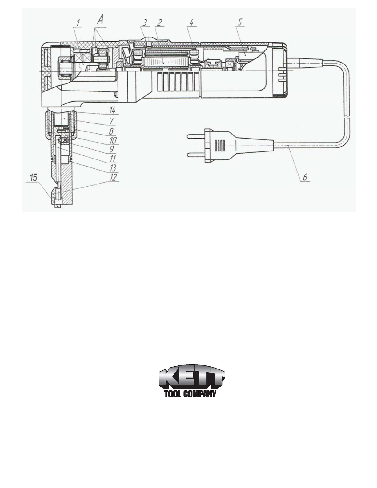
Pre-starting procedure (Fig. 1)
• Check all fasteners to be sure they are tight.
• Check the trigger (3) to see that it is moving freely.
Switching on and off (Fig.1)
• Move the trigger (3) forward to turn the nibbler ON; moving the trigger back turns the nibbler OFF.
• Red dot on the housing (4) near the trigger (3) shows that switch is in ON position.
Test run
Perform a no-load test run of 10-15 seconds prior to starting cutting.
Operating procedure
• With the nibbler ‘ON’ insert it into the cutting sheet at the lower V-shaped slot between the die holder (13) and the die (12).
• When cutting, hold the tool so, that the punch (11) is at a right angle to the sheet plane.
• Move the nibbler carefully without putting to much pressure in direction of the cut.
• The temperature of the gear box (1) and the front motor housing (4) should not exceed accordingly 108ºF and 90ºF above ambient. The cooling holes
should be always clean and un-obstructed.
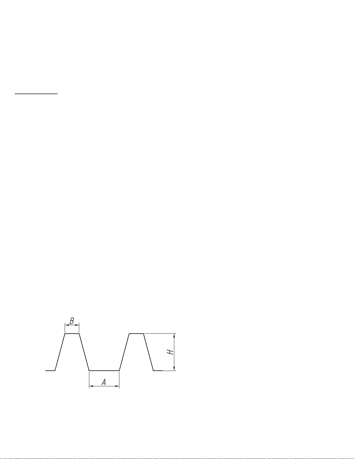
• For cutting within the sheet, it is necessary to drill a pilot hole with the minimum diameter of about 7/8 of an inc, large enough to insert the die
holder (13).
• Periodically, before beginning to work and after cutting about 5-6 feet of material, it is necessary to lubricate the punch (11) and the die (12).
Dip the end of the die holder into light oil 5/8” to 3/4” deep. Also, lightly lubricate the top surface of the metal sheet along the cutting line.
• It is recommended to take a break to cool the gear box to ambient temperature after cutting of every 12 to 15 feet in order to extend the tool life.
• Periodically lubricate the plunger (7) and the punch holder (10).
Punch and die replacement
When the cutting edges of the punch and/or die become worn, it is necessary to replace them. When replacing parts, clean all chips from the tool.
To replace the punch:
• Unfasten nut (8) and take the die holder (13) off.
• Place plunger (7) and punch (11) with the punch holder (10) to the bottom stroke by rotating the fan through holes in the gear box.
• Take the punch, the punch holder and plunger off.
• Unfasten the lock screw (9).
• Replace the punch.
• Fasten the punch lock screw.
• Re-assemble the tool.
• After replacing the punch, check the tool at no-load speed for 30-60 seconds. The die holder should not get warm.

To replace the die:
• Unfasten screws (15).
• Replace the die.
• Refasten screws (15).
Setting up the nibbler for corrugated sheets cutting
Sometimes you may find it easier cutting corrugated material with the tool turned sideways. To do so:
• Unfasten nut (8) 3 to 4 revolutions.
• Pull the die holder (13) out to disengage it from the internal locking notches.
• Turn the die holder (13) by 90˚relative to position shown in Fig.1.
• Push the die holder back in, making sure it has engaged the locking notches.
• Tighten nut (8) .
MAINTENANCE
• Before beginning any work on the nibbler, make sure the tool is unplugged.
• Any maintenance work should be performed by a qualified repairman.
• For safe and proper working, always keep the tools ventilation slots clean and unobstructed.
• Any serious repairs should be made by a KETT Tool service department.
• Periodically, depending on operation intensity, check the brushes and change them when their height is lower than 5/16
of an inch. When re-assembling, don’t change the brush position in the brush holder. When servicing, use only
identical replacement parts. Tool may be cleaned and lubricated by the user, but any other servicing, including the changing of
carbon brushes, should be performed by the manufacturer or any authorized representative or service station.
Cable
The cable or cord is the “life line” of your tool. Keep it clean by wiping it off occasionally. Keep it out of oils and greases. Coil it neatly when
not in use and avoid dragging it across sharp surfaces or using it as a handle to lift the tool.
When using the tool at a considerable distance from power source, an extension cable of adequate size must be used to prevent loss of
power and over-heating.
For extension cables up to 75 feet use number 18; for 100 feet use number 16; and for up to 200 feet use number 14 wire gage. If you are
working with a 230 volt fool, cable lengths may be doubled using the same wire gage sizes as prescribed above for the 120 volt tool.
KL-2030 Nibbler Corrugated Profile Cutting Capability Specs
Profile material should have geometry, complying with the following specs (in inches):
A from .787 to 6.3 and B over .787, H is less than 3;
A over 6.3 and B over .787, there are no limitations for H;
A less than .787 and B over .787, H is less than 1;
Both A and B less than .787, H is less than .197;
For round corrugations there are no limitations.
B-crest width; A-valley width; H-height
Pic. 1 – corrugated profile geometry

The Kett Tool Company
5055 Madison Road
Cincinnati, Ohio 45247
(513)271-0333
fax (513)271-5318
www.kett-tool.com
K12-390
\
1-Gear box
2-Electric motor
3-Trigger
4-Motor housing, front
5-Switch
6-Power cord
7-Plunger
8-Nut
9-Screw
10-Punch holder
11-Punch
12-Die
13-Die holder
14-Bushing
15-Screw
Fig. 1: KL-2030 nibbler main components
Table of contents
Other Kett Power Tools manuals