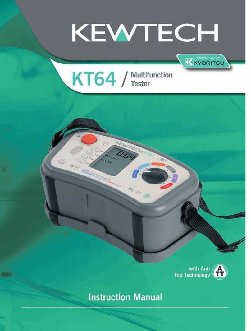
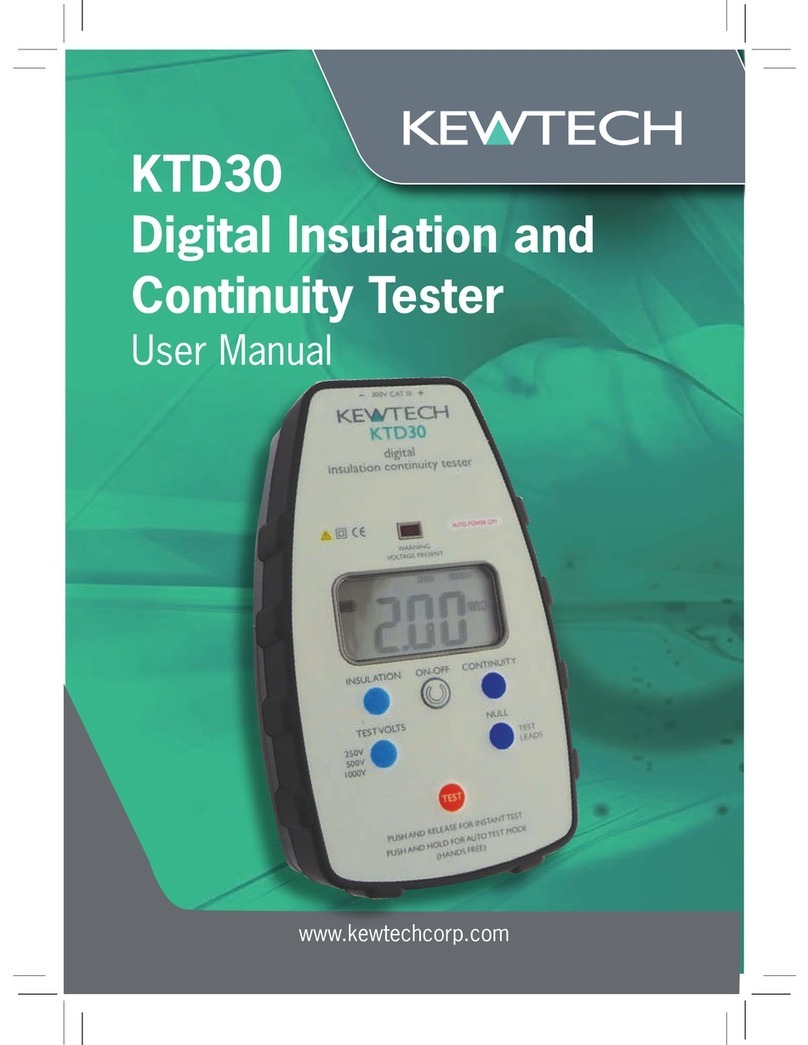
Kewtech KTD40 User manual

1
www.kewtechcorp.com
KTD40
Multifunction Digital
Loop Impedance Tester
User Manual

2
3
Caution
Before using your KTD40 please read these instructions; in particular note the safety
issues that follow:
• Althoughfullyprotectedupto440VACthistesterisforuseon230VACcircuits
only.
• Alwayscheckthetesteronaknown,correctlywired,livesocketoutletbeforeand
after use.
• Beforeusecheckyourtesterforanydamagetotheplug,leadandcabinet.
Important calibration/check box note
• BecauseoftheSuperSmartLoopTestSystemthetestisimmunetosuddenvalue
changes(suchasvoltagespikes).
• Asaresultwhenchangingcalibrationorcheckboxloopvaluestheunitmustbe
switchedoffbetweenchanges.
BSEN61010-1
AtKewtechourengineersconstantlylookforimprovement.Ifthereisanyaspectof
yourKewtechtesteryouwouldliketocommentonpleasevisitourwebsiteat
Kewtechcorp.com
Operation Overview
Your Kewtech tester has a special polarity test function.
ItisalittleknownfactthatasystemcanbereversewiredwithLine(Phase)toearth/
neutralandearth/neutraltoLine(Phase).Thesocketswillallworkandconventionalloop
testerswillshowandtestthateverythingiscorrectdespitethisverydangerouswiring
condition.
Althoughextremelyrare,thismiswireconditioncanexistsoifyourtestshowsthisfault
donotproceed–ifinanydoubtadviseyourcustomertocontacttheirsupplycompany
immediately.(Seeteststep 3,page9)
CORRECT POLARITY
Correct polarity
3
Operation overview
Your Socket & See tester has a special polarity test function.
It is a little known fact that a system can be reverse wired with Live (Phase) to
earth/neutral and earth/neutral to Live (Phase) The sockets will all work and
conventional loop testers will show and test that everything is correct despite
this very dangerous wiring condition.
Although extremely rare, this miswire condition can exist so if your test shows
this fault do not proceed – if in any doubt advise your customer to contact their
supply company immediately. (See test step 3, page 9)
FUSE 100A
From supply
company
LIVE (Phase)
NEUTRAL
Ty pical supply service
cut-out fuse
Live (Phase)
to meter
Neutral to meter
To main earthing
terminal
Solid brass
connecting block
FUSE 100A
From supply
company
NEUTRAL
LIVE (Phase)
Ty pical supply service
cut-out fuse
Neutral to meter
Live (Phase)
to meter
To main earthing
terminal
Solid brass
connecting block
REVERSE POLARIT Y
REVERSE POLARITY
LINE (Phase)
LINE (Phase)
NEUTRAL
NEUTRAL
LINE (Phase)
to meter
LINE (Phase)
to meter
To main earthing
terminal
Neutral to meter
To main earthing
terminal
The Kewtech KTD40 Loop Impedence Tester is designed for use by suitably
qualified personnel familiar with electrical supply systems.

4
5
Operation overview
TheKTD40willtestforNo-triploop,HighcurrentTrueLoopImpedance,No-tripPFC/
PSC(ProspectiveFaultCurrent),HighcurrentPSCusingTrueLoopImpedance,mains
voltage(L-N,L-EandN-E)andcorrectsocketwiring,inadditiontotheincomingsupply
polaritycheckdescribedonthepreviouspage.
AnotheruniquefeatureofyourKTD40testeristhehighcurrent2-wiremeasurementof
theTLI(TrueLoopImpedance).Regulationsandguidancebooksrefertoloopimpedance
measurementsbutupuntilnowlooptestersmeasuredloopresistancewhichisdifferent
fromloopimpedance,particularlywhentestingclosetothemainsupplytransformer.
Thisfunctionisthereforerecommendedwhentestingforexternalearthfaultloop
impedance(Ze)atdistributionboardsonnonTTsystemsandsimilarpointsonthe
supplysideofanySwitch/RCDgearandwhentestingtheLine/Neutrallooptodetermine
prospectiveshortcircuitcurrent.
ItisthevariationinpowerfactorthatmakestheTLImeasurementofyourKTD40so
muchmoreaccuratethanolderlooptestingtechniques.(Becauseofthistheremaywell
bevariationsinreadingscomparedtoordinarylooptestersortheno-tripfunctionofthis
tester,particularlywhenthemeasurementismadeneartothemainsupplytransformer).
TheKTD40alsohasaNo-triptestmodethatisguaranteednottotripa30mAorhigher
ratedRCDprovidingthatthecircuitisotherwisehealthy.
No-trip vs High current testing
AlthoughtheKTD40HighcurrentTLImeasurementmodeisinherentlymoreaccurate
thanconventionaltechniqueswhenmeasuringclosetothemainsupplytransformer,the
differencebetweenresistanceandtrueimpedancereducesthefurtherawayfromthe
transformer the measurement is made.
ThisiswhyusingtheNo-tripmodeissuitableformeasurementonnalcircuitsand
similarlyremotepoints.ItshouldbenotedhoweverthatwhilstNo-triptestingatthese
locationswillnormallyfunctionatasimilarhighlevelofaccuracy,thelowcurrent
measurementtechniqueusedismorelikelytobeadverselyaffectedbyexternalfactors
suchascontactresistance(e.g.whentestingatseldomusedsocketoutlets)andcircuit
noise(e.g.switchedmodepowersupplyonthesamecircuit).Thiscanresultinthe
occasional erroneous reading.
Forthisreasonitisrecommendedthatmultiplemeasurementsaremadewhenusingthe
No-tripmodeandanyisolatedoddresultsareignored.Whentakingmultiplereadingsthe
testerorthesupplyshouldbepoweredoffbetweenconsecutivetests.Wherepractical
otherequipmentpoweredbythesamesocketshouldbeturnedoff.
ForsafetyreasonsNo-tripmodeisrecommendedforallmeasurementsmadeonTT
systems.
Test lead configuration
Important
TheKTD40canbeusedwith2differenttypesofconnectinglead.Itisimportantto
understandandusethecorrectleadcongurationforeachtestmodeoryoumaynot
obtainthecorrectresults.
Leadoptions
1 Ref:KAMP13 Themainslead(IECC13to13Aplug)typeconnectorthatis
supplied with the tester.
2 Ref:ACC016E The3-Polefuseddistributionboardtestleadsetwhichterminates
infusedprods/crocodileclips.Thisissuppliedasaseparateaccessorytothe
KTD40.
Theleadisanintegralpartofthetesterset-upandshouldaccompanythetesterwhen
beingreturnedforre-calibrationorservice.Donotuseanyothertypeofmainsleador
fusedtestleadsetasitwouldbelikelytogiveincorrectresults.
Lead configuration for No-trip testing
This is the default mode that the KTD40 will start in when turned on. This mode is most
usefulfortestingatsocketoutlets,luminaires,wiringterminals,etc.ininstallations
wherethecircuitundertestmaybeprotectedbyanRCD.
InNo-tripmodethetestercanbeusedwiththemainsleadwhentestingat13Asocket
outlets,orthedistributionboardleadsetfortestingatotherpointsinthecircuit.
WhentestingwiththeKTD40inNo-tripmodethe3colourcodedprods/crocodileclips
ofthetestleadshouldbeconnectedtothecorrespondingLine,NeutralandEarth
terminals.
Thismodecanbere-selectedatanytimebypressingbutton5labelled‘No-trip’.

6
7
Test lead configuration
Lead configuration for High Current 2-wire testing with TLI feature
TheTLI(TrueLoopImpedence)functionisintendedforuseatdistributionboardsand
similarpointswhereyouaremeasuringonthesupplysideofanySwitch/RCDgear.
TheTLImeasurementfunctionisselectedbypressingbutton9labelled‘Ze/DB’.This
functionusesthemaximumhighcurrentofthetesterandrequirestheuseofthe
distributionboardleadsetconguredin2-wiremode.Donotusethisfunctionwiththe
mainsleadorthedistributionleadsetin3-wiremode.
Toarrangethetestleadsin2-wiremodepulltheblueprodoffthebluetestleadand
plugtheexposed4mmconnectorintothebackofthegreenconnectorasshownbelow.
YouwillnowhavetheEarthandNeutralleadsconnectedtogetherreadyforconnection
totheEarthorNeutralconductortobetested.
Operation – a Detailed View of the KTD40
2 ThreeLEDsshow
socket wiring
status
4 LCD-default
L-Nvoltage
measurement
1 On/Offbutton
5 No-triploopselect
(default)
7 No-tripPFC
(prospectivefault
current)
6 Pushtostarttest
9 Highcurrent
loop impedance
test
8 Voltageselect
L-N(default)L-E
andN-E
3 PolarityTest
10 Highcurrent
PFCtest

8
9
Overview of the Display
A Loopreadingselected(Ω)
B PFC/PSCprospectivefaultcurrent/prospectiveshort
circuitcurrentreadingselected(A/kA)
C Looptestmodeselected–notrip(default)orHi-I(highcurrent)
D HANDSFREEoperation
E Ohmssymbol
F Volts(AC)
G VoltagemeasurementfunctionL-N(default)L-EandN-E
H Faultcurrent
I Wait–resultcalculationinprogress
J Wait–testerhasgoneoveroperatingtemperature
K BatteryCondition(=good)
L Greaterthan(>)lessthan(<)indication
Loop-PFC/PSC Testing
1 PowerON/OFF–PressingthisbuttonturnstheKTD40onandpressingagainturns
theunitoff.Intelligentautopower-offoccursafter3minutesofinactivity,butfor
safety the instrument stays powered if it is displaying a socket wiring fault.
2 WhentheKTD40isrstconnectedtoalivesocketitwillautomaticallytest
thesocketwiringtoestablishthatthecircuitwireshavebeenconnectedtothe
correctterminalsonthebackofthesocket.IfallthreeLEDslightGREENandno
sound is emitted the wiring status is correct and you can proceed to the incoming
supplypolaritytest(step3).
Afaultwiththesocketwiringwillbeindicatedbyanaudiblealternatingtoneand
theLEDs,atleastoneofwhichwillberedororange,willash.Ifafaultindication
isgiven–DONOTPROCEED–investigationandremedialactionisrequiredbefore
you can conduct a loop test.
Ifthishappensplacingyourthumbonthegreycolouredpolaritytestpadwillnow
activatethe‘faultlocation’function.Withyourthumbrmlyonthepadcheckthe
indicationgivenbytheLEDsagainstthechartonthebackcovertoidentifywhere
themainproblemlies.
Note: ThecolouroftheLEDsmaychangewhenthepadistouched.
3 IncomingsupplyPolarityTest–thisimportanttestisdiscussedinfullon
page3ofthismanual,pleaseread.
ToconductthetestwithallthreeLEDslitGREENplaceyourthumbonthegrey
colouredpolaritytestpadarea.Ifthesupplypolarityiscorrecttherewillbeno
changeinindicationandyoucanproceedtostep4.Ifthesupplypolarityhasbeen
reversedthethreeLEDswillturnredandash.
Ifthishappensstoptestingandnotifythesupplycompanyimmediately.
4 Checkthatthemainsvoltageisinthecorrectrange207–253VAC.
Note: Alltestsareinhibiteduntilthemainsvoltageappearsinthedisplay.
5 NO-TRIP Yourtesterdefaultstono-triplooptestingwhenyourstswitchon–
buttonvere-selectsno-triplooptestifyouhaveselectedotherfunctions.
6 TEST Abriefpressofthetestbuttonwillinitiatethelooptestandafterafew
secondstheresultwillbedisplayed(Important:seenotesonpage4).
TheKTD40alsohasaHANDSFREEtestfunctionthatisactivatedbypressingthe
testbuttonbeforeconnectingtothemainssupply.Thisisveryusefulfortestingat
luminairesorsimilarconnectingstripswhenyourhandsareoccupiedbyholding
thetestprobes.
LOOPPFC –PSC HANDSFREE
WAIT
NO-TRIPH
I
-
I
K
J
H
C
E
B
kA
VLE
NE
A D
F
H
LG
I
PRESS AND HOLD
Ω

10
11
Loop-PFC/PSC Testing - continued
WhenusingHANDSFREEmodewiththedistributionboardtestleadsetalways
connecttheEarthandNeutralpolesbeforetheLine,otherwiseitwillindicatea
polarityfaultandinhibitfurthertesting.
HANDSFREE testing in No-trip mode.
The tester will automatically conduct the socket wiring test upon connection to the
Livesupply.IfalliswellitwillimmediatelyinitiateaLooptest.
Whenthetestiscompletetheresultwillbedisplayedforafewsecondsbeforethe
displayrevertstoshowingtheL-Nvoltage.
TheLooptestresultcanberecalledbypressingtheNo-tripbuttonandthePFC/
PSCresultcanberecalledbypressingtheNo-tripPFCbutton.
7NO TRIP PFC HavingcarriedoutaNo-tripEarthfaultlooptest–pressingthis
buttoncalculatesthePFC(ProspectiveFaultCurrent)bydividingthemeasuredloop
resultintothemeasuredL-Evoltage.
8 VOLTAGE ThedefaultvoltagemeasurementismadebetweenL-N.Usingthis
buttonyoucanoverridetomeasureL-Eandasanalsafetycheckmeasurethe
N-Evoltagepresent.
9 Ze/DB ThisbuttonselectstheHighCurrentTrueLoopImpedancemode.Useonly
withthetestleadsetconguredfor2-wiremode(seepage6).
Connectthetestleadstothetwoconductorsbeingtested.Thesupplyvoltage
(seestep8)willbedisplayed.AbriefpressofthetestbuttonwillconducttheLoop
testandtheresultwillbedisplayedalmostimmediately.
Note: In2-wiremodethevoltagedisplayedwillbethatmeasuredacrossthe2
conductorsthatthetestleadsareconnectedto.ThedisplaywillshowthisasL-N
regardlessofwhethertheyareconnectedacrossL-NorL-E.
HANDSFREE testing in High current 2-wire mode.
Thisfunctionisparticularlyusefulfortestingatdistributionboardsandisactivated
bypressingthetestbuttonbeforeconnectingtothemainssupply.TheKTD40
willthenautomaticallyconductaLooptestuponconnectiontothelivesupply
anddisplaytheresult.ThesupplyvoltagecanberecalledbypressingtheVoltage
buttonandthePFC/PSCresultcanberecalledbypressingtheNo-tripPFCbutton.
10 PFC/PSC ProspectiveFaultCurrent/ProspectiveShortCircuitCurrent.Pushing
thisbuttondividestheaboveTLI(TrueLoopImpedance)resultintothevoltage
measuredbetweenthetwopointsundertesttogiveeithertheprospectiveshort-
circuitcurrent(whenL-Nistested)ortheprospectiveearthfaultcurrent(whenL-E
istested).
Specifications
Wiring Test
DetectsmissingEorN(>15kΩ)
DetectsL-EorL-Nswap
DetectsLive–Earth/NeutralreversalbyuseofPolarityTestPad
Phase–Neutralvoltagemeasurement ±1%±1V
Phase–Earthvoltagemeasurement ±1%±1V
Neutral–Earthvoltagemeasurement ±1%±1V
Loop Test
Notripmode3wiretestingPhase–Neutral–Earthallconnected
Testcurrent<15mAat253VAC
Range Accuracy
0.00to9.99Ω ±5%±5digits
10.00to99.9Ω ±3%±3digits
100.00to500Ω ±3%±3digits
Highcurrentmode2wiretestingPhase-NeutralorPhase-Earthconnectedusingtrue
impedancemeasurement–autotest(handsfree)isselectable.
Range Accuracy
0.00to9.99Ω ±3%±3digits
PFC/PSC Measurement
10A–19.9kA Thisisacalculatedresultusingthelooptestmeasurementbut
itwillbeinherentlymoreaccuratethantraditionalmethodsas
the test is of impedance not solely resistance.
Over Voltage Protection
440VAC Nodamage–completerecovery
Power
4×AAbatteries(notincluded)
Batterylife(BSEN61557)>10,000test(orshelflifeofbatteriesinstalled)
Environmental
OperatingTemperatureRange
0°Cto40°C
StorageTemperatureRange
–10°Cto+60°C
OperatingHumidity 93%RH@40°C
Size 157mm×89mm×39mm
Weight 400g

12
www.kewtechcorp.com
Kewtech Corporation Limited
MidasHouse,Unit2b,StonesCourtyard,HighStreet,Chesham,BucksHP51DE
T: 01494 792 212
F:01494791826
Condition Wiring Supply LED Buzzer
Number Condition Terminal Display
N E L
Socket Wiring
1 Correct N E L Continuous
2 L-E reverse N L E Warble
3 L-N-E miswire E L N Warble
4 L-N reverse L E N Warble
5 L-N-E miswire L N E Warble
6 Faulty N / L-E miswire NC L N Warble
7 Faulty N / E miswire NC N L Warble
8 Faulty N NC E L Warble
9 Faulty N / L-E reverse NC L E Warble
10 Faulty E / L-N reverse L NC N Warble
11 Faulty E N NC L Warble
12 Faulty E / N miswire E NC L Warble
13 Faulty E / L-N miswire L NC E Warble
14 Faulty L / N-E miswire L N NC Warble
15 Faulty L / E miswire N L NC Warble
16 Faulty L / N-E miswire E L NC Warble
17 Faulty L / N miswire L E NC Warble
18 No Mains NC NC NC None
Above is the indication given when touching the touch pad.
LEDs will flash to indicate fault condition NC = No Connection
Table of contents
Other Kewtech Measuring Instrument manuals