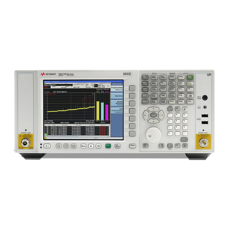
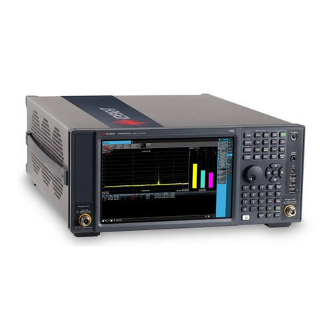
Keysight N9038A Installation and operation manual

Notice: This document contains references to Agilent.
Please note that Agilent’s Test and Measurement
business has become Keysight Technologies. For more
information, go to www.keysight.com.
Keysight N9038A MXE EMI Receiver
Option HL4
High Performance
Digital Signal Processing Upgrade
Installation Note

Notices
© Copyright 2013-2019 Keysight Technologies, Inc.
The information contained in this document is subject to change without notice.
Keysight Technologies makes no warranty of any kind with regard to this material, including but
not limited to, the implied warranties of merchantability and fitness for a particular purpose.
Keysight Technologies shall not be liable for errors contained herein or for incidental or
consequential damages in connection with the furnishing, performance, or use of this material.
Manual Part Number
N9038-90018
Edition
Edition 1, February 2019
Supersedes: June 2018
Printed in USA/Malaysia
Published by:
Keysight Technologies, Inc.
1400 Fountaingrove Parkway
Santa Rosa, CA 95403

Installation Note N9038-90018 3
Option HL4 - High Performance Digital Signal Processing Upgrade
This document provides detailed instructions for the installation of Option HL4 - High Performance
Digital Signal Processing in an N9038A MXE EMI Receiver. Please be sure to read this entire
document before attempting to perform this upgrade.
Products Affected: N9038A MXE EMI Receiver
Requirements: — Instrument Software Version A.13.60 or newer
— Access to the Instrument Administrator Login
— Keysight N7818A MXE Calibration and
Adjustment Software (revision E.09.03 or later)
To Be Performed By: (X) Service Center
( ) Advanced User
()User
Estimated Installation Time:
Estimated Adjustment Time:
Estimated Verification Time:
3.0 Hours
4.0 Hours (All Adjustments Required)
8.0 Hours (Full Performance Verification Required)

4Installation Note N9038-90018
Option HL4 - High Performance Digital Signal Processing Upgrade
Contents
Tools Required
Quantity Description Part Number
1 A2 Enhanced Analog IF Board Assembly N9020-60290
1 A3 High Performance Digital IF Board Assembly N9038-60116
1 A15 Enhanced Front End Control Board Assembly N9020-60172
1 W7 Ribbon Cable Assembly - A3J20 to A2J820 N9020-60046
1 W12 Wire Harness Assembly - A15J300 to A12J1 N9020-60059
1 W14 Coaxial Cable Assembly - A13J7 to A15J902 8121-1862
1 W15 Coaxial Cable Assembly - A15J901 to A3J15 8121-1919
1 W16 Coaxial Cable Assembly - A15J900 to A2J100 8121-1865
1 W17 Coaxial Cable Assembly - A2J601 to A3J19 8120-8868
1 W22 Coaxial Cable Assembly - A15J1100 to Rear Panel AUX IF OUT 8121-1859
1 W23 Coaxial Cable Assembly - A16J726 to A3J17 8121-1401
1 Wire Marker #6 7121-5606
6Nylon Cable Tiea
a.Six cable ties are included with this kit so that ones that need to be cut during the installation process can
be replaced and new cables can also be secured, use as needed.
1400-0249
3 Screw, M3X0.5, 8mm Long, Pan Head 0515-0372
2 Screw, M2.5X0.45, 6mm Long, Pan Head, Patch-Lock 0515-1940
2 Hex Standoff, 4-40, 0.312 inch Long, Patch-Lock 0380-1858
1 Option N9038AK-HL4 License Entitlement Certificate n/a
—TorxDriverT-20
—TorxDriverT-10
— Torx Driver T-8
— 9/16” Nut Driver
— 5/16” Nut Driver
— 3/16” Nut Driver
— 5/16” Open End Wrench
— Needle Nose Pliers
— Diagonal Cutters
— USB Storage Device
—USBMouse
—USBKeyboard

Installation Note N9038-90018 5
Option HL4 - High Performance Digital Signal Processing Upgrade
What you will find in this document
ESD Information
Protection from Electrostatic Discharge ................................................................ page 6
Handling of Electronic Components and ESD ....................................................... page 7
Test Equipment Usage and ESD ............................................................................. page 7
For Additional Information about ESD ................................................................... page 7
Installation Instructions
Instrument Software Version Verification .............................................................. page 8
Instrument Dress Cover Removal ........................................................................... page 9
Top Brace and Power Supply Bracket Removal.................................................. page 10
Rear Panel Removal ............................................................................................. page 12
Right Outer Chassis Side Removal...................................................................... page 13
Front End Control Assembly Removal................................................................. page 14
Enhanced Front End Control Assembly Installation ........................................... page 15
Analog/Digital IF Assembly Removal .................................................................. page 16
Enhanced Analog IF/High Performance Digital IF Installation .......................... page 19
Rear Panel Installation ......................................................................................... page 23
Miscellaneous IF Cable Installation..................................................................... page 24
Right Outer Chassis Side Installation.................................................................. page 25
Top Brace and Power Supply Bracket Installation.............................................. page 26
Instrument Dress Cover Installation .................................................................... page 26
New Hardware Driver Installation........................................................................ page 27
License Key Retrieval and Installation ................................................................ page 30
FPGA Programming .............................................................................................. page 30
Installation Verification ........................................................................................ page 31
Adjustments and Performance Verification
Adjustments Required.......................................................................................... page 32
Performance Testing Recommended .................................................................. page 32
6Installation Note N9038-90018
Option HL4 - High Performance Digital Signal Processing Upgrade
ESD Information
Protection from Electrostatic Discharge
Electrostatic discharge (ESD) can damage or destroy electronic components. All work on electronic
assemblies should be performed at a static-safe workstation. Figure 1 shows an example of a
static-safe workstation using two types of ESD protection:
— Conductive table-mat and wrist-strap combination.
— Conductive floor-mat and heel-strap combination.
Both types, when used together, provide a significant level of ESD protection. Of the two, only the
table-mat and wrist-strap combination provides adequate ESD protection when used alone. To
ensure user safety, the static-safe accessories must provide at least 1 megohm of isolation from
ground.
Figure 1 Example of a Static-Safe Workstation
These techniques for a static-safe workstation should not be used when working on circuitry
with a voltage potential greater than 500 volts.

Installation Note N9038-90018 7
Option HL4 - High Performance Digital Signal Processing Upgrade
Handling of Electronic Components and ESD
The possibility of unseen damage caused by ESD is present whenever components are transported,
stored, or used. The risk of ESD damage can be greatly reduced by paying close attention to how all
components are handled.
— Perform work on all components at a static-safe workstation.
— Keep static-generating materials at least one meter away from all components.
— Store or transport components in static-shielding containers.
Test Equipment Usage and ESD
— Before connecting any coaxial cable to an analyzer connector, momentarily short the center and
outer conductors of the cable together.
— Personnel should be grounded with a 1 megohm resistor-isolated wrist-strap before touching
the center pin of any connector and before removing any assembly from the analyzer.
— Be sure that all analyzers are properly earth-grounded to prevent build-up of static charge.
For Additional Information about ESD
For more information about preventing ESD damage, contact the Electrical Over
Stress/Electrostatic Discharge (EOS/ESD) Association, Inc. The ESD standards developed by this
agency are sanctioned by the American National Standards Institute (ANSI).
Always handle printed circuit board assemblies by the edges. This will reduce the possibility of
ESD damage to components and prevent contamination of exposed plating.

8Installation Note N9038-90018
Option HL4 - High Performance Digital Signal Processing Upgrade
Installation Instructions
Instrument Software Version Verification
1. Determine what version of instrument software is currently installed in the MXE being
upgraded by pressing the following front panel keys:
System, Show, System
The software revision can be found on this screen as the:
Instrument S/W Revision
If a software update is required, the latest version of MXE instrument software and installation
instructions can be downloaded from:
http://www.keysight.com/find/mxe_software
Once the instrument software requirement has been met proceed to step 2.
If the instrument software version is not A.13.60 or higher it will need to be updated before
proceeding with this upgrade.

Installation Note N9038-90018 9
Option HL4 - High Performance Digital Signal Processing Upgrade
Instrument Dress Cover Removal
2. Turn the instrument off and remove the ac power cord.
3. Refer to Figure 2. Using the T-20 driver, remove the four screws (1) that attach the strap
handles (2) to each side of the instrument.
4. Remove the four bottom feet and locks (6) by lifting the tabs on the feet and sliding them to
disengage from the outer case.
5. Using the T-20 driver, remove the four screws and washers (3) that hold the four rear feet (4)
in place.
6. The instrument dress cover (5) can now be removed by pulling it off to the rear of the
instrument.
Figure 2 Instrument Dress Cover Removal
If the instrument is placed on its face during any of the following procedures, be sure to use a soft
surface or soft cloth to avoid damage to the front panel, keys, or input connector.

10 Installation Note N9038-90018
Option HL4 - High Performance Digital Signal Processing Upgrade
Top Brace and Power Supply Bracket Removal
7. Refer to Figure 3. Using the T-10 driver remove the twelve pan head screws (3) (0515-0372)
attaching the MP10 Top Brace (1) to the chassis, along the Cable Hold Down 1
as shown in Figure 4.
8. If Option LSN is installed remove the two flat head screws (7) (0515-1227) attaching the top
brace to the A30 LISN Control board assembly.
9. Remove the fifteen flat head screws (4) (0515-1227) attaching the top brace to the board
assemblies. The top brace can now be removed.
10.Using the T-10 driver remove the eight pan head screws (5) (0515-0372) and the three flat
head screws (6) (0515-1227) attaching the MP9 Power Supply Bracket (2) to the instrument.
The power supply bracket can now be removed.
Figure 3 Top Brace and Power Supply Bracket Removal

Installation Note N9038-90018 11
Option HL4 - High Performance Digital Signal Processing Upgrade
Figure 4 Cable Hold Downs

12 Installation Note N9038-90018
Option HL4 - High Performance Digital Signal Processing Upgrade
Rear Panel Removal
11.Refer to Figure 5. Using the 9/16” nut driver remove W21 External Reference Input Cable (2)
from the instrument rear panel EXT REF IN port.
12.If they are installed, using a 3/16” nut driver remove the two hex standoffs (7) (0380-1858)
that attach the W9 LISN Control Cable to the instrument rear panel AUX I/O port (6). These
standoffs will not be reused.
13.Using the T-10 driver, remove the sixteen pan head screws (4) (0515-0372) attaching the
MP6 Rear Panel (1) to the instrument. The rear panel can now be removed.
Figure 5 Rear Panel Removal

Installation Note N9038-90018 13
Option HL4 - High Performance Digital Signal Processing Upgrade
Right Outer Chassis Side Removal
14.Refer to Figure 6. Using the T-10 driver remove the two flat head screws (3) (0515-1035)
attaching the MP5 Right Outer Chassis Side (1) to the front frame assembly.
15.Using the T-10 driver, remove the eight pan head screws (2) (0515-0372) attaching the right
outer chassis side to the instrument. The right side outer chassis can now be removed.
Figure 6 Right Outer Chassis Side Removal
The two flat head screws (0515-1035) used to attach the MP5 Right Outer Chassis Side to the
front frame assembly are longer than the rest of the flat head screws removed during this
upgrade. Be sure to note this fact once they are reused so that they will be sure to go back to the
correct location during reassembly

14 Installation Note N9038-90018
Option HL4 - High Performance Digital Signal Processing Upgrade
Front End Control Assembly Removal
16.Refer to Figure 7. Remove W3, W4, W5, and W12 from the A15 Front End Control board
assembly (1).
17.Remove W27 from J103 of the A23 Limiter Assembly to allow clearance for the removal and
installation of the A15 Front End Control board assembly.
Figure 7 Old A15 Front End Control Board Cable Locations
18.Using the board extractor (2) carefully remove the A15 Front End Control board assembly (1).
This assembly will not be reused.

Installation Note N9038-90018 15
Option HL4 - High Performance Digital Signal Processing Upgrade
Enhanced Front End Control Assembly Installation
19.Refer to Figure 8. Carefully install the new A15 Enhanced Front End Control board assembly,
moving W27 out of the way as needed so that no components on the assembly are damaged.
Make sure that the assembly connector fully engages with the A8 Motherboard connector.
20.Reconnect W27 to J103 of the A23 Limiter Assembly. Torque to 10 inch-lbs.
21.Reconnect W3 to J800 of the A15 Enhanced Front End Control board assembly.
22.Reconnect W4 to J700 of the A15 Enhanced Front End Control board assembly.
23.Reconnect W5 to J102 of the A15 Enhanced Front End Control board assembly.
24.Reconnect W12 to J300 of the A15 Enhanced Front End Control board assembly.
Figure 8 New A15 Enhanced Front End Control Assembly Cable Locations
The location of J300 on the new A15 assembly may be in a different location than it was on the
A15 assembly that was removed. If needed a new shorter W12 cable assembly (N9020-60059)
is included with this kit.

16 Installation Note N9038-90018
Option HL4 - High Performance Digital Signal Processing Upgrade
Analog/Digital IF Assembly Removal
25.Refer to Figure 9. Remove W17 from J601 of the A2 Analog IF assembly (1).
26.Remove W19 from J300 of the A2 Analog IF assembly (1).
27.Remove W16 from J100 of the A2 Analog IF assembly (1) and from J7 of the A13 Front End
assembly.
28.Remove W16 from the instrument, cutting any wire ties necessary. This cable will not be
reused.
Figure 9 Old A2 Analog IF Assembly Cable Locations
29.Refer to Figure 10. Remove W20 from J14 of the A3 Digital IF assembly (1).
30.Remove W17 from J15 of the A3 Digital IF assembly (1).

Installation Note N9038-90018 17
Option HL4 - High Performance Digital Signal Processing Upgrade
Figure 10 Old A3 Digital IF Assembly Cable Locations
31.Slide the A2 Analog IF / A3 Digital IF assembly out the rear of the instrument. This assembly
will not be reused.
The A3 Digital IF assembly has two connectors that will need to disengage from the A8
Motherboard assembly as the assembly is slid out.
32.Remove the spiral wrap holding W17 and W20 together (2) at the rear of the instrument and
remove W17 from the instrument. This cable will not be reused.
W17 is the 190 mm long cable that connected A2 J601 to A3 J15. It has numbering of 601 on
one end and 15 on the other.

18 Installation Note N9038-90018
Option HL4 - High Performance Digital Signal Processing Upgrade
33.Refer to Figure 11. Remove W20 from J710 of the A16 Reference assembly (1).
34.Using the number “6” provided (7121-5606), change the number on the end of W20 that was
removed from J710 of the A16 Reference assembly (1) from “710” to “716”.
35.Reconnect W20 to J716 of the A16 Reference assembly (1) instead of J710.
36.Moving the connection point of W20 on the A16 Reference assembly will leave extra slack in
the cable. Pull this slack down to the side of the instrument.
Figure 11 A16 Reference Assembly Connections

Installation Note N9038-90018 19
Option HL4 - High Performance Digital Signal Processing Upgrade
Enhanced Analog IF/High Performance Digital IF Installation
37.Refer to Figure 12. Attach either end of the new W7 cable (N9020-60046) to J20 of the new A3
High Performance Digital IF assembly (2) (N9038-60116).
38.Position the A3 High Performance Digital IF assembly (2) onto the new A2 Enhanced Analog IF
assembly (1) (N9020-60290).
39.Using the T-10 driver attach the IF assemblies together with the three pan head screws (3)
(0515-0372) provided. Torque to 9 inch-lbs.
40.Connect the other end of W7 to J820 of the A2 Enhanced Analog IF assembly (1).
Figure 12 Enhanced Analog IF / High Performance Digital IF Assembly
41.Insert the A2 Enhanced Analog IF / A3 High Performance Digital IF assembly into the rear of
the instrument, making sure that the two A3 assembly connectors properly and fully engage
with the A8 Motherboard connectors.
42.Refer to Figure 9. Connect the loose end of W19 (labeled “300”) to J300 of the A2 Enhanced
Analog IF assembly.
43.Connect the new W17 cable (9120-8868) end labeled “601” to J601 of the A2 Enhanced
Analog IF assembly. Be sure to position the cable such that it is routed between the screw
holding the corner of the board shield to the board and the board shield itself.

20 Installation Note N9038-90018
Option HL4 - High Performance Digital Signal Processing Upgrade
44.Refer to Figure 13. Connect the new W16 cable (8121-1865) end labeled “100” to J100 of the
A2 Enhanced Analog IF assembly. Be sure to position the cable such that it is routed between
the screw holding the corner of the board shield to the board and the board shield itself.
Figure 13 A15 Enhanced Front End Control Assembly IF Cable Locations
45.Refer to Figure 13. Connect the other end of W16 (labeled “900”) to J900 of the A15 Enhanced
Front End Control assembly. Route the cable along the top of the instrument fans between the
two left chassis side panels.
46.Refer to Figure 14. Connect the loose end of W20 (labeled “14”) to J14 of the A3 High
Performance Digital IF assembly (1).
47.Connect the loose end of W17 (labeled “19”) to J19 of the A3 High Performance Digital IF
assembly (1).
Other manuals for N9038A
4
Table of contents
Other Keysight Receiver manuals

Keysight
Keysight N9038A User manual

Keysight
Keysight N9038A Installation and operation manual

Keysight
Keysight N9038A Installation and operation manual

Keysight
Keysight x series User manual

Keysight
Keysight N9048B PXE Installation and operation manual

Keysight
Keysight N9038B Quick start guide

Keysight
Keysight N5991 User manual

Keysight
Keysight x series User manual

Keysight
Keysight N9038A-503 User manual