manuals.online logo
Brands
  1. Home
  2. •
  3. Brands
  4. •
  5. Kicker
  6. •
  7. Speakers
  8. •
  9. Kicker 19418149 User manual

Kicker 19418149 User manual

Other Kicker Speakers manuals

Kicker KS Series User manual

Kicker

Kicker KS Series User manual

Kicker 45KM44 User manual

Kicker

Kicker 45KM44 User manual

Kicker YJ-SPKUP User manual

Kicker

Kicker YJ-SPKUP User manual

Kicker 49ST4TW User manual

Kicker

Kicker 49ST4TW User manual

Kicker DS350 User manual

Kicker

Kicker DS350 User manual

Kicker 48BTCAN65 User manual

Kicker

Kicker 48BTCAN65 User manual

Kicker KM4 User manual

Kicker

Kicker KM4 User manual

Kicker KPM50 User manual

Kicker

Kicker KPM50 User manual

Kicker BT Cans User manual

Kicker

Kicker BT Cans User manual

Kicker KM4 User manual

Kicker

Kicker KM4 User manual

Kicker KSC350 User manual

Kicker

Kicker KSC350 User manual

Kicker KPW2 User manual

Kicker

Kicker KPW2 User manual

Kicker KS Series User manual

Kicker

Kicker KS Series User manual

Kicker PSC57 User manual

Kicker

Kicker PSC57 User manual

Kicker 47KSMT25 User manual

Kicker

Kicker 47KSMT25 User manual

Kicker KM6200 User manual

Kicker

Kicker KM6200 User manual

Kicker PS5250 User manual

Kicker

Kicker PS5250 User manual

Kicker PSC65 User manual

Kicker

Kicker PSC65 User manual

Kicker KM620 User manual

Kicker

Kicker KM620 User manual

Kicker KM44CW User manual

Kicker

Kicker KM44CW User manual

Kicker 41KPWB User manual

Kicker

Kicker 41KPWB User manual

Kicker KSS50 User manual

Kicker

Kicker KSS50 User manual

Kicker DS35 User manual

Kicker

Kicker DS35 User manual

Kicker KSMT25 User manual

Kicker

Kicker KSMT25 User manual

Popular Speakers manuals by other brands

Electro-Voice LR4S engineering data

Electro-Voice

Electro-Voice LR4S engineering data

Definitive Technology Sound Cylinder user guide

Definitive Technology

Definitive Technology Sound Cylinder user guide

AudioSource LS545 user manual

AudioSource

AudioSource LS545 user manual

Paso C402-T Instructions for use

Paso

Paso C402-T Instructions for use

Altec Lansing 416-8C LF SPEAKER manual

Altec Lansing

Altec Lansing 416-8C LF SPEAKER manual

Kenwood KFC-1072 Servise manual

Kenwood

Kenwood KFC-1072 Servise manual

Peavey ProSys 112 user guide

Peavey

Peavey ProSys 112 user guide

JBL Control Contractor 60 Series installation instructions

JBL

JBL Control Contractor 60 Series installation instructions

Aura STORM-8 owner's manual

Aura

Aura STORM-8 owner's manual

Oontz ANGLE 3 PLUS quick start guide

Oontz

Oontz ANGLE 3 PLUS quick start guide

Electro-Voice LR4A engineering data

Electro-Voice

Electro-Voice LR4A engineering data

Rave RK-650-ICA-B owner's manual

Rave

Rave RK-650-ICA-B owner's manual

Flux Reference Series installation manual

Flux

Flux Reference Series installation manual

Lanzar AQAWBS64BK installation manual

Lanzar

Lanzar AQAWBS64BK installation manual

DAPAudio DCS-6230 manual

DAPAudio

DAPAudio DCS-6230 manual

Aluratek ABS03F quick start guide

Aluratek

Aluratek ABS03F quick start guide

Kenwood KES-5A instruction manual

Kenwood

Kenwood KES-5A instruction manual

Sonance ORIGINAL SERIES instruction manual

Sonance

Sonance ORIGINAL SERIES instruction manual

manuals.online logo
manuals.online logoBrands
  • About & Mission
  • Contact us
  • Privacy Policy
  • Terms and Conditions

Copyright 2025 Manuals.Online. All Rights Reserved.

1

©2022 Stillwater Designs
19418149-20220920

19418149
Designed for 2019 and newer
Chevrolet® Colorado and
GMC® Canyon Crew Cab
without HD radio
Not Compatible with Bose® system
AmplifierAssembly
SubwooferHarness
SubwooferPowerHarness
AmplifierPowerHarness
M6BoltX2
7mmScrew
ThreadedClip
FuseX2
WireTieX6
FoamPadX3
AmplifierHarness
SubwooferAssembly
2

Fig. 2
Insert terminals first.
Any wire can be in
an
y
position.
Then
close
retainer
Fig. 3
Fig. 1
1. Disconnect negative battery cable.
2. Make sure supplied fuses are not installed in fuse holders. Open the battery distribution cover
and connect the subwoofer power wire and the amplifier power wire to the stud pictured in
figure 1 depending on which distribution block you have. Torque to 4.7Nm (42in-lb)
3. Route the power harnesses toward the firewall and secure with supplied wire ties.
4. Make a small incision in the grommet on the driver
side of the firewall and pass the power harnesses
into the cabin. Some models may have a small
nipple that can be cut off rather than making an
incision. Fig. 2
5. Install the white three pin power connector on the
amplifier power harness. Close the retainer. Fig. 3
Note: The terminals are keyed so that they only
install one way. If the terminal doesn’t want to
slide completely into the connector, it may
need to be rotated 180 degrees. It does not
matter which red wire goes in what position of
the connector.
Tip: Using a piece of stiff wire can help
in feeding the wires through the
grommet. Poke the stiff wire through
from inside the cabin and then tape the
power harnesses to the wire. Try to tape
the power wire so that the metal
terminals are not all trying to pass
through the grommet at the same time.
Slowl
y
p
ull the stiff
p
iece of wire to feed
3

Insert
terminal
first
Then
depress
blue
retainer
Fig. 4
6. Install the black two pin power connector on the
subwoofer power harness by first inserting the
terminal fully into the connector and then
depressing the blue retainer. Fig. 4
Note: Make sure the blue retainer in the center
of the connector is not depressed –it should
be flush with the front of the connector. If the
retainer is depressed, the terminal will not fully
seat in the connector body. Make sure the
terminal is installed into position 1 on the
connector body. There should be a block-out plug installed in position 2 in order to
prevent the terminal from being installed into the wrong position on the connector.
Radio Removal
7. Pull loose the radio bezel. Fig. 5
8. Remove the four screws securing the radio display/HVAC control panel. Fig. 6
9. Pull loose radio display/HVAC control panel and disconnect wiring. Note: Be careful not to
allow metal retainers to scratch dash!
Multi-Channel Amplifier Installation
10. Pull loose the dash end trim panel on the passenger side of dash. Fig. 7
11. Pull loose the passenger side front kick/threshold trim panel. Fig. 8
Fig. 6
Fig. 8
Fig. 5
Fig. 7
4

Fig. 12
Fig. 9
Fig. 11
Fig. 10
12. Remove the five screws and one plastic retainer securing the passenger side lower cover panel
below the glove compartment. To remove the plastic retainer, pry the center portion out first.
Fig. 9
Note: Some models may have a smaller
panel with only three screws.
13. Remove the glove compartment hinge pins by sliding them out. Fig. 10
14. Remove the glove compartment tension cable by sliding the hook toward the front of the glove
compartment. Remove the glove compartment from dash. Fig. 11
15. Install the supplied M6 clip nut onto the plastic tab
on the side of the blower housing. Fig. 12
Note: Some models may have a metal threaded
insert installed into the plastic tab by the
factory. If a metal threaded insert is present,
remove it and replace with the supplied M6 clip
nut.
5

Fig. 13 Fig. 14
Fig. 16
Fig. 15
16. Temporarily disconnect the HVAC blower fan wiring to allow the amplifier to be installed.
17. Secure the top of the multi-channel amplifier bracket with the supplied M6 bolt – leave loose.
Fig. 13
18. Install the supplied M6 bolt to secure the bottom of the multi-channel amplifier bracket to the clip
nut – leave loose. Fig. 14
19. Install the supplied screw in the location indicated in Fig. 15 and then tighten both M6 bolts.
Amplifier Harness Routing
20. Route the multi-channel amplifier harness from the
radio opening to the amplifier in a way that will not
interfere with the glove compartment function or
reinstallation of the radio display/HVAC control
panel.
21. Disconnect the 28-pin tan connector from the radio
module and connect it to the amplifier harness.
Fig. 16
6

Fig. 19
22. Connect the tan connector of the amplifier harness back to the radio module.
23. Disconnect the 28-pin green connector from the radio module. Carefully cut away
approximately 3 inches of black cloth wrapping the harness. Find the green with black stripe
wire and cut. Strip back about ¼ inch of wire on each cut end. Fig. 17
24. Using the supplied butt connectors, connect the harness wire labeled “connector” to the cut
wire attached to the radio connector. Connect the harness wire labeled “harness” to the other
cut wire. Fig. 18 See Splicing Technique Section.
25. Connect the two white multi-channel amplifier
connectors to the amplifier.
26. Ground the multi-channel amplifier harness to the
bolt securing the right side of the dash.
Fig. 19 Tighten to 19Nm (14ft-lb)
27. Connect the multi-channel amplifier harness three-
pin power connector to the three-pin power
harness connector.
Subwoofer Harness routing
28. Remove the driver side front and rear threshold panel along the bottom of the door opening.
29. Remove the filler panel on each side of the rear seat frame trim panel. Fig. 20
30. Remove the eleven bolts and rubber bumpers securing the rear seat frame trim panel and
remove the trim panel from vehicle. Fig. 21
Fig. 17 Fig. 18
Fig. 20 Fig. 21
7

Fig. 22
31. Connect the subwoofer harness two-pin power connector to the power harness two-pin
connector.
32. Route the subwoofer input connector (two-pin white) under the dash toward the passenger side
and connect it to the multi-channel amplifier connector.
33. Ground the subwoofer harness to the bolt securing
the left side of the dash. Fig. 22 Tighten to 19Nm
(14ft-lb)
34. Route the subwoofer harness along the driver side door openings. Pull harness under carpet
and through hole near rear seat frame on the driver side. Fig. 23
35. Make two ½ inch long cuts in carpet directly below the metal brace pictured in Fig. 24. Only cut
through the carpet layer, and not the insulation. The cuts should be approximately ½ inch apart.
36. Slide one of the supplied wire ties under the loop of carpet created in the previous step and
secure the harness to the carpet loop. Fig.25
37. Connect the subwoofer harness to the subwoofer. After connection, secure connector to
retention bracket on the bottom of the subwoofer enclosure.
38. Push down firmly on the subwoofer to slide it under the rear seat frame. Make sure the
subwoofer bracket is fully installed over the nut insert in the rear seat frame. Install the supplied
foam pieces along the front of the subwoofer enclosure where indicated in Fig. 26
Maketwo
cutsincarpet
approx.½
inchlongand
½inchapart
directly
belowmetal
brace!Cut
carpetonly,
not
insulation!
5inches
fromback
ofbar
Fig. 24
Fig. 25
Foampads
Fig. 26
Fig. 23
8

Fig. 27
39. Reinstall the rear seat frame trim panel over the
subwoofer enclosure and reinstall the bolts and
bumpers. It may be necessary to make slight
adjustments to the subwoofer enclosure or rear
seat trim panel position to perfectly center the
enclosure. Reinstallation of the two filler panels on
each side of the seat frame trim panel is possible,
but not necessary. Fig. 24
40. Reinstall all previously removed parts in reverse
order.
41. Install supplied fuses into fuse holders.
42. Reconnect negative battery cable. Tighten to 7.5Nm (66in-lb)
9

Troubleshooting the Kicker Integrated Systems
If you experience a problem once the subwoofer or amplifier are installed use this guide to locate the trouble.
The radio is working, but the Subwoofer is not working:
 Check the battery voltage to make sure it is not discharged below 11 volts.
 Check the negative battery cable to see if it has been securely tightened back on the battery.
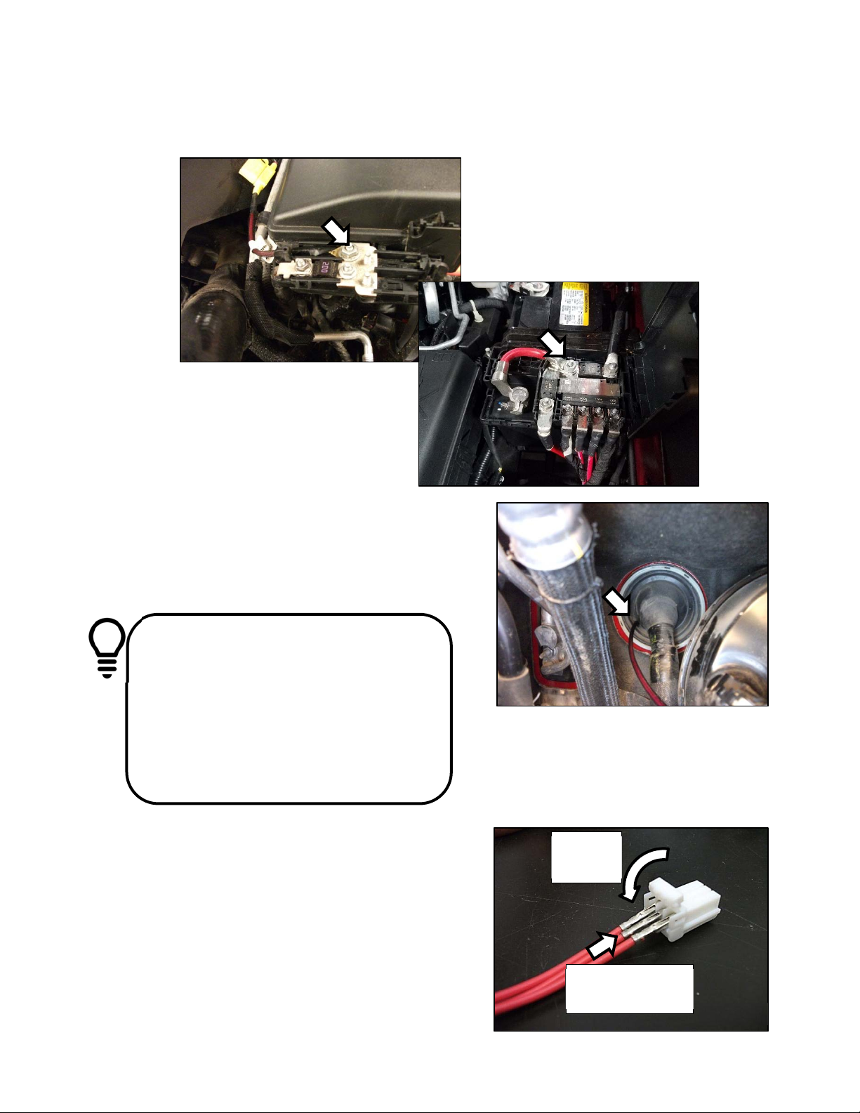
 Check the inline fuse located near the battery to make sure it is plugged in completely, and not blown.
 Check the inline +12 volt power connector near the firewall to make sure it is plugged in securely.
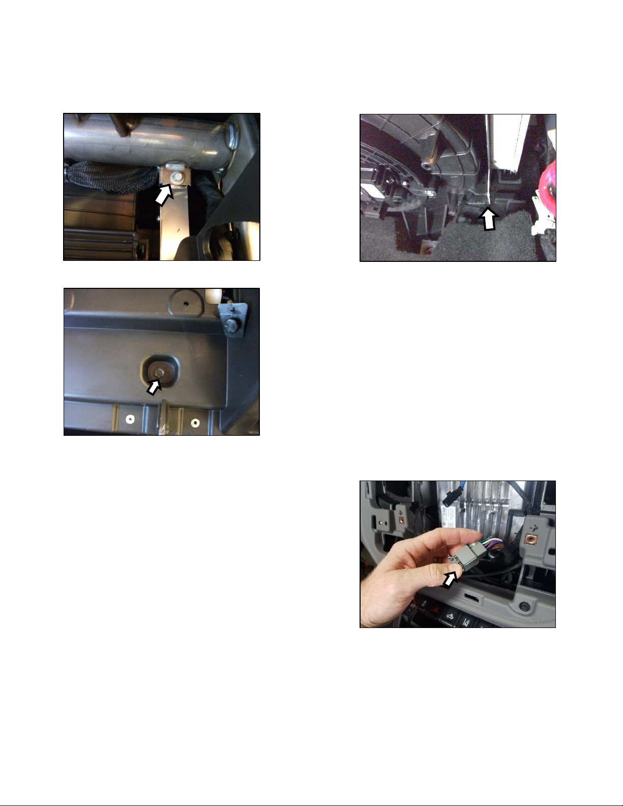
 Check the inline connectors near the subwoofer enclosure to make sure they are plugged securely.
 Check the ground wire connection to make sure it is tightly secured to the proper ground in the vehicle.
 Check the audio input signal connection to make sure it is secure and connected to the proper wiring.
 Test with different music in case there is no low frequency audio in the initial sound check.
There is a problem with the multi-channel stereo amplifier:
 Check the battery voltage to make sure it is not discharged below 11 volts.
 Check the negative battery cable to see if it has been securely tightened back on the battery.
 Check the inline fuse located near the battery to see if it is plugged in completely and not blown.
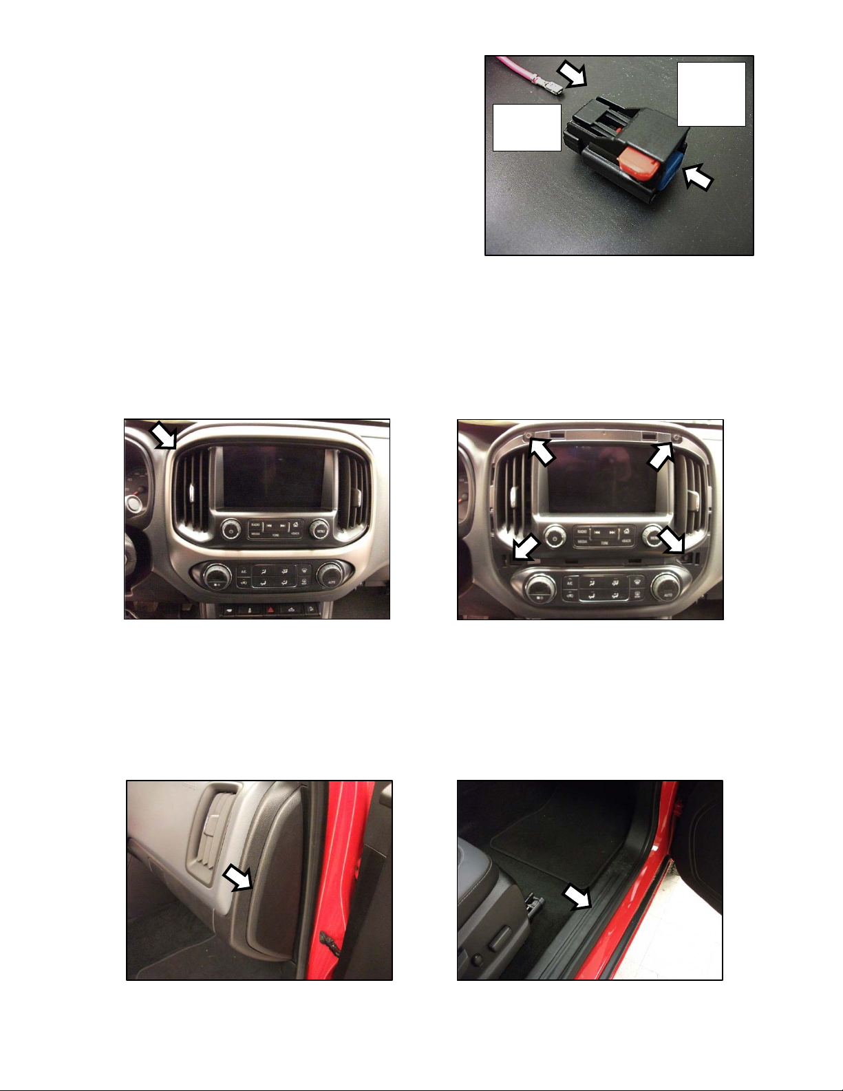
 Check the multi-pin connectors at the back of the radio and at the amplifier chassis to make sure they are
plugged all the way in.
 Check the ground wire connection to make sure it is tightly secured to the proper ground in the vehicle.
Symptom Possible Cause Solution
No Subwoofer Output
Fuse not installed in inline fuse
holder on subwoofer and/or
amplifier power harness
Install fuse into fuse holder.
Refer to instructions for correct
placement
Low battery voltage Recharge the battery
Negative battery cable not
connected
Reconnect negative battery
cable
Power wire connector not
connected to body harness
Connect power wire to body
harness. Check for loose
connection
Ground wire not grounded properly Check ground wire with voltmeter
to insure it is a good ground
Balance and/or fader controls not
set to neutral position
Set balance and fader control to
center settings. (only affects
stand-alone subwoofer kit)
No low frequency information in
music Test with several different songs
Subwoofer harness not
properly/completely connected to
subwoofer
Securely fasten both of the
connectors on the subwoofer
harness to the subwoofer.
Check for loose connectors.
Radio Not Coming On Blown radio fuse Refer to owner’s manual for radio
fuse location and value
Low battery voltage Recharge the battery
Radio Comes On, But No
Sound From Any Speakers
Fuse not installed in inline fuse
holder on amplifier harness
Install fuse into fuse holder.
Refer to instructions for correct
placement
Ground wire not grounded properly Check ground wire with voltmeter
to insure it is a good ground
Low battery voltage Recharge the battery
10

SplicingTechnique
Splicing Copper Wire Using Splice Sleeves
Special Tools:
•
EL-38125-10 Splice Sleeve Crimping Tool
•
J-38125-5A Ultra Torch Special Tool
•
J-38125-8 Splice Sleeve Crimping Tool
NOTE: The DuraSeal splice sleeves have the following 2 critical features:
•
A special heat shrink sleeve environmentally seals the splice. The heat shrink sleeve contains a
sealing adhesive inside.
•
A cross hatched (knurled) core crimp provides the necessary low resistance contact integrity
for these sensitive, low energy circuits.
Use DuraSeal splice sleeves where there are special requirements such as moisture sealing. Follow the
instructions below in order to splice copper wire using DuraSeal splice sleeves.
Splice Sleeve Color Crimp Tool Nest Color Wire Gauge mm² / (AWG)
3 Crimp Nests 4 Crimp Nests 

Salmon (Yellow-Pink) 
19168446 Red (1) or Red/Green Red (2) 0.5–0.8/(18–20)
Blue 
19168447 Blue (2) Blue (3) 1.0–2.0/(14–16)
Yellow 
19168448 Yellow (3) Yellow (4) 3.0–5.0/(10–12)
NOTE: You must perform the following procedures in the listed order. Repeat the procedure if any wire
strands are damaged. You must obtain a clean strip with all of the wire strands intact.