III. Set Function Options and Operating Instructions
1. After switching on the power, to enter into the function menu, press the “Esc” key on the
panel for 3 seconds, following which password input is required to enter the menu.
2. Open Bluetooth of PTM and connect PTM to WSCBSN.
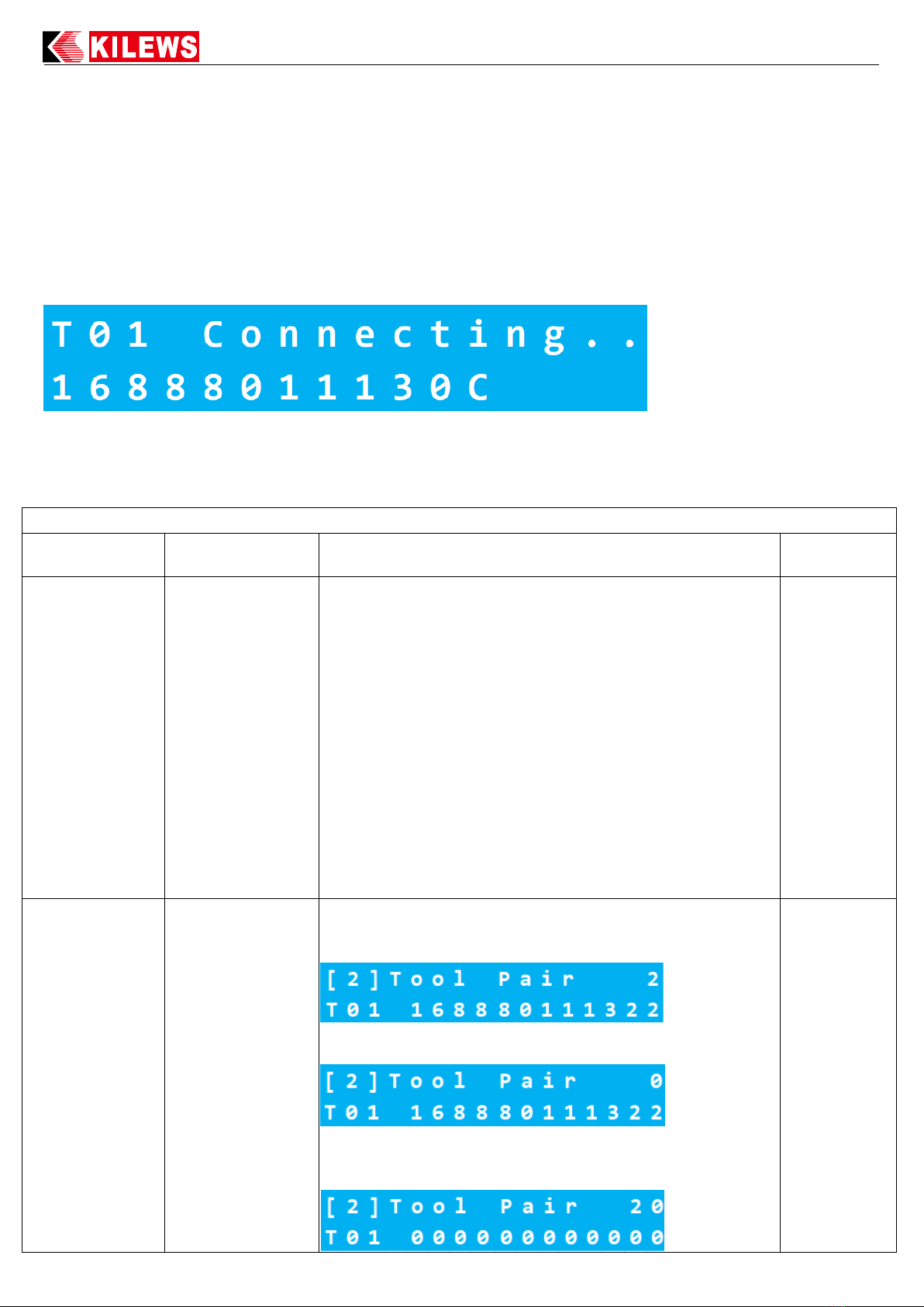
3. After setting, press "ESC". It will show PTM connecting as below
4. When the PTM does not run for over 30 mins, it will enter the sleep mode. Press trigger to
activate.
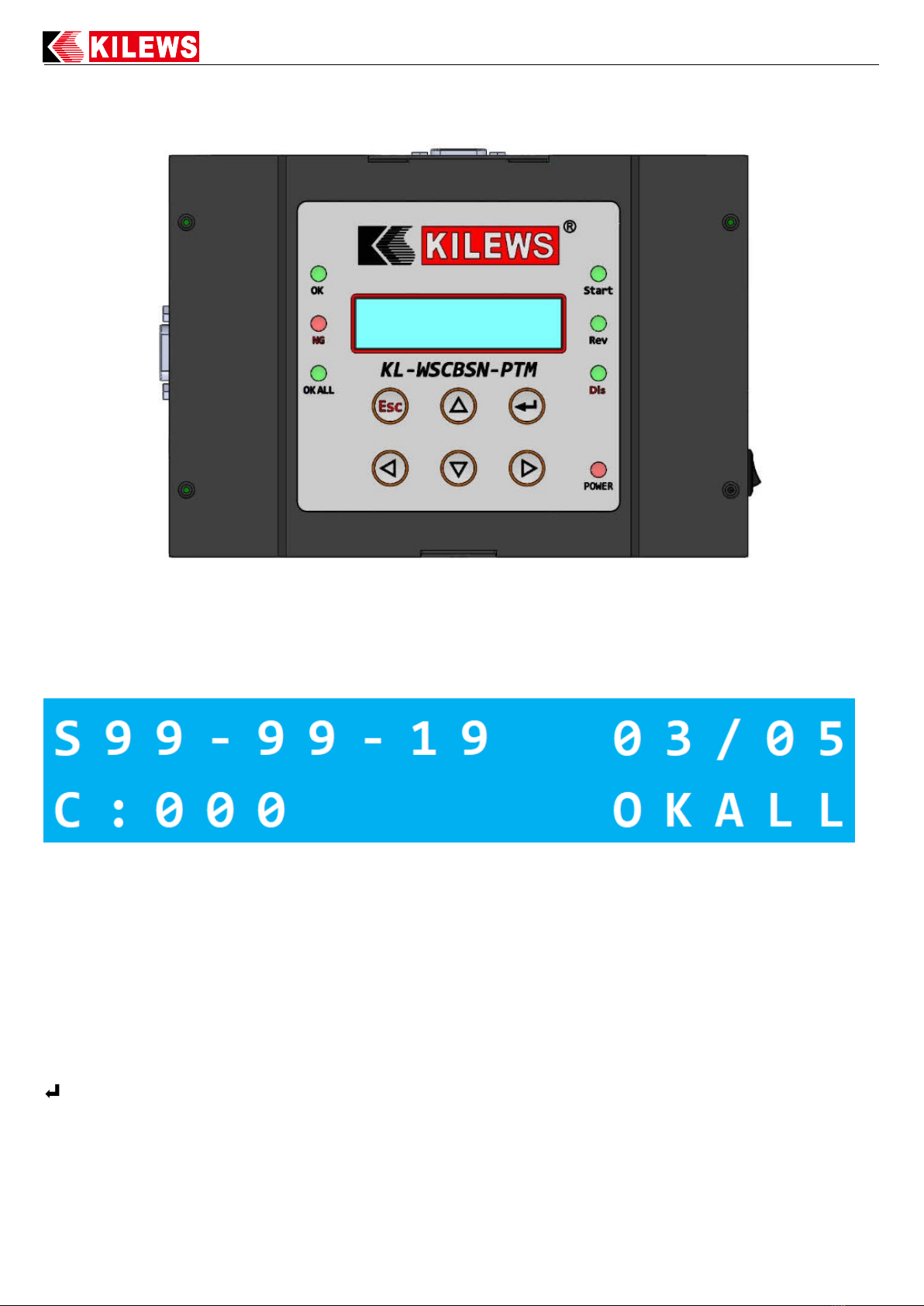
xxxxxxxxxxxx
(1). Search PTM list and find PTM Bluetooth MAC number,
it is able to choose PTM by order via [2] Tool Pair. For
example: A-3 168880111302, “A” mean total 9 PTM, “3”
mean the 3rd PTM, “168880111302” mean MAC number.
Press Up/Down to check, and confirm by Enter.
(2). We suggest to connect PTM to WSCBSN one by one.
Follow first step to detect 2nd, 3rd. WSCBSN is able to detect
19 PTM.
(3). If user take Bluetooth dungle of PTM to WSCBSN, it
will became Master. After user take Bluetooth dungle to
PTM. It have to close PTM Bluetooth and open again. That
Bluetooth dungle will become Slave and able to dected by
WSCBSN by Query Tool function.
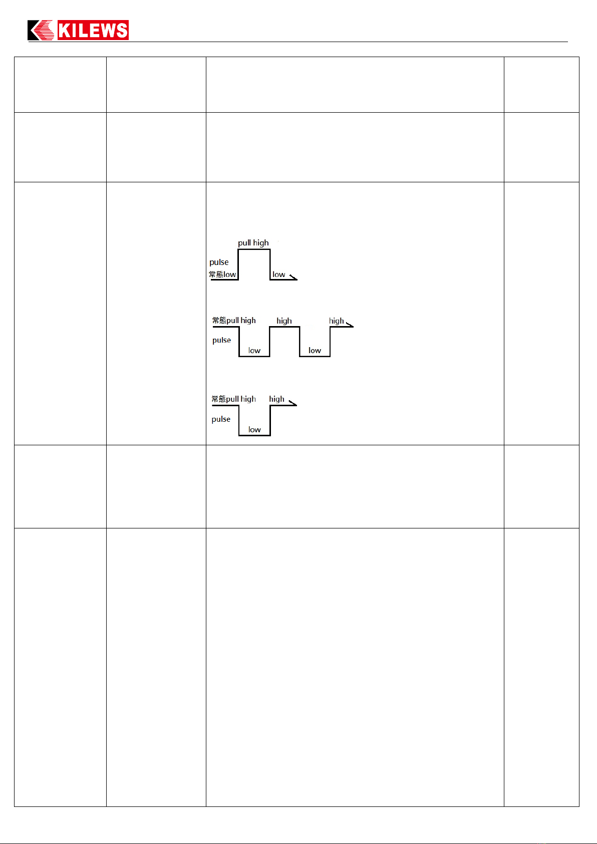
MAC number of
Tools
(1). Press left/right to select PTM(T01...T02...etc), and press
enter to let MAC number blink. And then press up/down to
select Tool Pair 1~19 and press enter to save.
(2). While MAC number blink, Tool Pair number become 0,
it means PTM match MAC number completed.
(3). While MAC number blink, select Tool Pair 20 and MAC
number is 000000000000. Press enter the Matched PTM and
its MAC number will be cleared.