Premier Elite 12-W/24-W/48-W Quick Start Guide
6 INS531-4
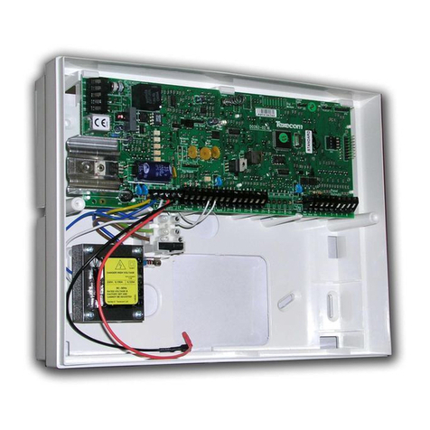
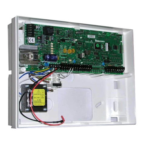
20: Ricochet Firmware Flash Port
Connections for flasher interface to update Ricochet receiver firmware.( factory
function only)
21: Commission Mode Jumper
Fit when learning and placing devices, remove once complete.
22: Antenna
RF antenna (1 on 12-W/24-W 2 on 48-W)
23: RF LED’s
Left = RED Transmit, Middle = GREEN Receive, Right = RED Wireless
Network Tick.
24: Plug-on Communicator Connections
This socket provides connection for Premier COM300/COM2400 plug-on
communicators via the lead provided.
25: Ricochet Comm. Port Connection (24/48-W Only)
Serial communications port for connecting to a PC via PC Com/USB Com or
Com IP for use with Ricochet Monitor Software.
26: Cover Tamper
Provides tamper protection for the control panel.
27: Heartbeat LED/Power Light
Flashes steadily to indicate that the control panel is functioning correctly. If the
light is ON or OFF all the time, then there could be a problem.
28: Cover Tamper Disable
Disables the lid tamper
29: Flash Programming Port
For upgrading the panel firmware.
30: Battery Charge Selection(24/48-W Only)
Select .03A or 0.75A battery charging current
31: Current Reading Pads
To calculate the current draw of the control panel, measure the voltage across
the two pads and multiply by 10 i.e. Reading = 34mV (x10) = 340mV =
340mA.
32: Battery Kick-start Button
When powering up the panel without AC Mains present, this button must be
pressed in order to connect the battery. If AC Mains is present this button does
not need to be pressed.
33: Power Supply Connection
Only for use with the Texecom PSU.
DO NOT CONNECT ANY OTHER MAINS SUPPLY TO THESE TERMINALS
PTC Protection Fuses
The following fuses are provided:
F6 PTC (0.9A) Auxiliary 12V Power fuse
F4 PTC (0.9 A) Network 1 fuse
F5 PTC (0.9 A) Bell/Strobe fuse
Ricochet V2.xx
Multiple Expander Support
It is now possible to add multiple expanders to the system allowing for greater
flexibility in system design, and also taking wireless capability to new levels.
Additional device modes and diagnostics functions also give more information
about the system status, and allow greater control over devices modes of
operation.
Control Panel Capacity
The table below details the maximum number of expanders, devices and
Premier Elite SmartKey™ that may be used on the different control panels,
other configurations may be possible.
Panel
32XP-W (*Onboard) 8XP-W(*Onboard)
Expanders Devices
Premier Elite
SmartKey™ Expanders Devices
Premier Elite
SmartKey™
Premier
Elite™ 12-
W
N/A N/A N/A 1* 8 8
Premier
Elite 24-
W™
1* 16 16 N/A N/A N/A
Premier
Elite 48-
W™
1* 32 16 3 32 50
Premier Elite 32XP-W take 4 address slots on the network, Premier Elite 8XP-W
take one address
DO NOT mix V1 & V2 expanders on the same system.
System Requirements
To enable all of the advanced functionality and diagnostics capability of the V2
upgrade the following are minimum requirements:-
•Wintex™ Version 6.1 or later
•Ricochet Monitor 0.2.18.00 or later
•Premier Elite™ Series V2.10 or later
•Premier Elite™ 32XP-W & 8-W Expanders V2.13 or later
System Design Considerations
When using multiple expanders great care should be taken when designing the
system. Each expander should be treated as its own wireless network; it is not
possible for devices to hop from one wireless network to the other, it is also not
possible for expanders to pass wireless signals from devices not assigned to
them and nor can the expanders talk to each other.
Learning Devices
All devices should be learnt before they are placed in their final location. The
expander should be in commission mode, (see INS467 for details). This will
ensure that they are registered on the receiver or control panel, and that Mesh
Networks and routeing are established correctly. Please refer to the relevant
section in this document to Learn Devices to the system.
Devices should be at least 30cm’s away from the receiver when being learned.
Learning Premier Elite SmartKey™
Premier Elite SmartKey™ should be learned AFTER all other systems devices
and expanders have been learned and setup, this will ensure you can choose
the correct routeing for the Premier Elite SmartKey™ and that it will function in
the correct areas of the premises
Expander Addressing (not 12-W)
Introduction
The address range and switch position will depend on which combination of
expanders are being used. Each 32XP-W takes up 4 address slots on the
control panel network, however the network slots are virtual until devices are
assigned to available zones. It is possible that if a 32XP-W is being used at
Address 1, but only 16 devices have been used, Address 3 & 4 are available for
hardwired 8XP's or 8XP-W's.
Please see below some examples of mixing different types of Expanders on
various Elite panels and the addressing requirements.
Premier Elite™48-W, + 8XP's
Panel Network 1
Expanders (Mixed)
Premier Elite 48™ 32XP-W 2 x 8XP
Expander Address 1 5 & 6
Devices Used 16 16
Premier Elite SmartKey™(Max) 16 N/A


