Kilowatt Labs Sirius 3550-48-B-1.7C-M-SD-A-L-19G User manual

SIRIUS CAPACITOR MODULE
User Manual
Model number: 3550-48-B-1.7C-M-SD-A-L-19G
Version 1.0; Release Date: Aug 2019
Author:
Mamoona Khalid

Introduction
The Sirius Capacitor Module (“Sirius”) is supercapacitor-based storage that uses supercapacitors as
storage cells instead of chemical cells. Kilowatt Labs’ proprietary balancing, control and charge
retention algorithms control the operation of the supercapacitor-based modules, making Sirius a safe,
efficient and effective alternative to chemical batteries wherever chemical batteries are deployed.
Legal Provisions
No part of this User Manual (“Manual”) may be reproduced, or transmitted, in any form or by any
means, without the prior written permission of Kilowatt Labs, Inc. (“Kilowatt” or the “Company”).
Specifications in this Manual are subject to change without notice. While every attempt has been
made to make the Manual accurate and up-to-date, users are cautioned that product improvements
may cause the Company to make changes to specifications without advance notice. Users are
encouraged to consult the Company or its Resellers before using the Manual. Neither the Company
nor its Resellers shall be liable for any indirect, incidental, or consequential damages under any
circumstances caused by reliance on the material presented, including, but not limited to, omissions,
typographical errors, arithmetical errors or listing errors in the content material. The content of this
manual shall not be modified without the written authorization of the Company.
Trademarks
All trademarks are recognized, even if not explicitly identified as such. Kilowatt Labs® is a registered
trademark of the Company.

Sirius Capacitor Module –User Manual Model Number - 3550-48-B-1.7C-M-SD-A-L-19G
This manual is subject to change without notice and at the sole discretion of Kilowatt Labs, Inc.
Kilowatt Labs, Inc. | www.kilowattlabs.com
3
Contents
1 Safety Instructions: .........................................................................................................................5
1.1 Symbols Convention: ..............................................................................................................5
1.2 Safety Precautions: .................................................................................................................5
1.3 Modules Connection Safety Precautions:...............................................................................6
1.4 Shipping: .................................................................................................................................7
1.5 Qualified Installer:...................................................................................................................7
2 Product Introduction:......................................................................................................................7
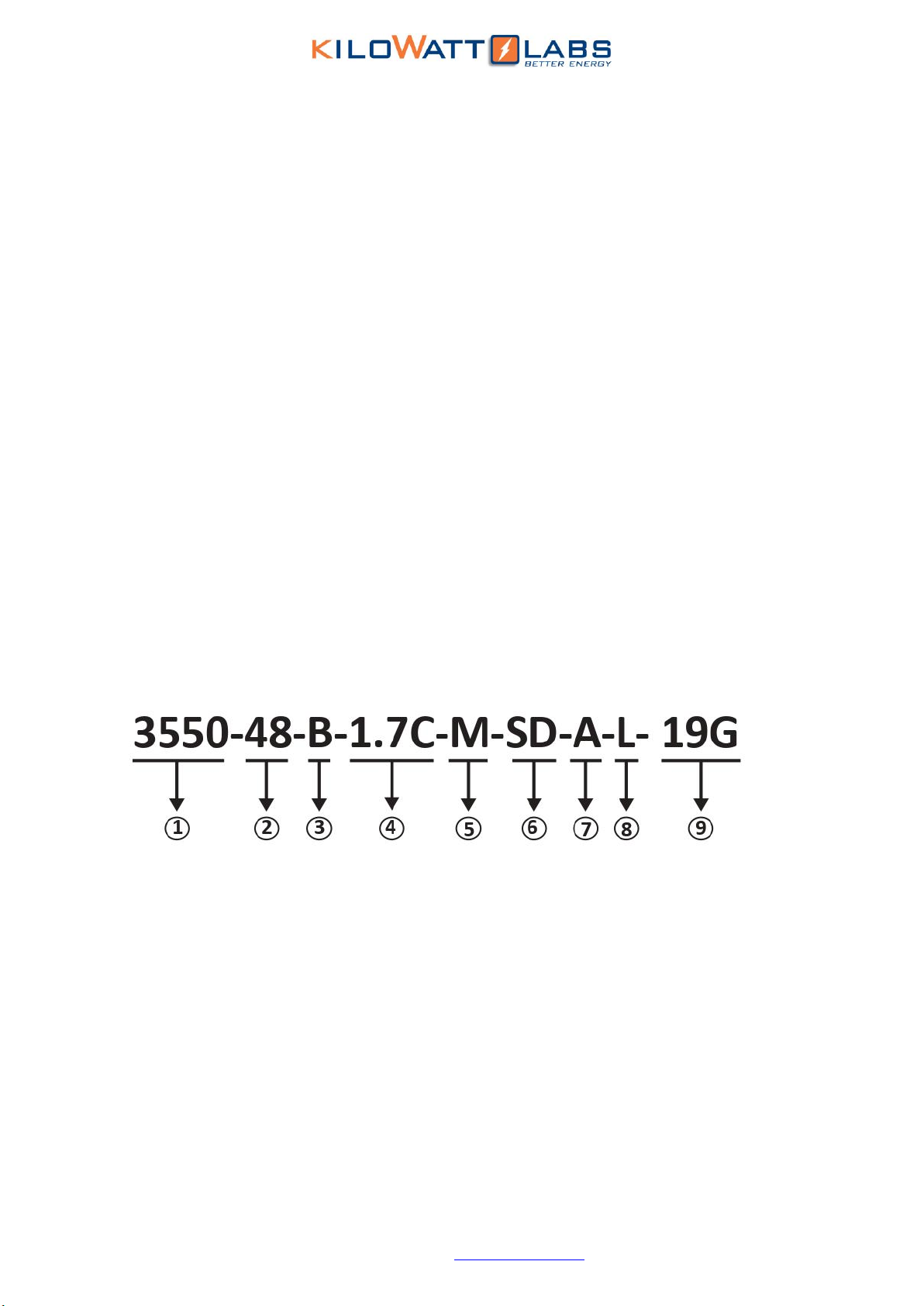
2.1 Product Part Number:.............................................................................................................7
2.2 Product Overview: ........................................................................................................................8
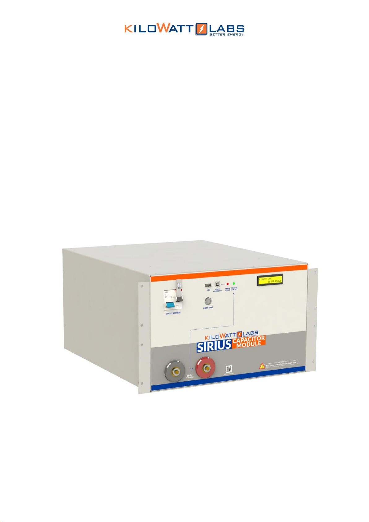
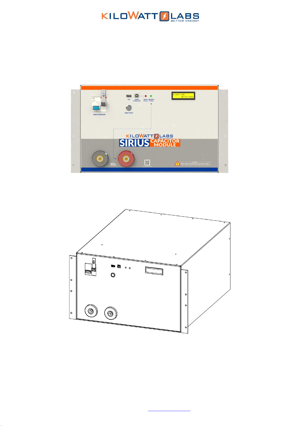
2.2.1 Appearance:.............................................................................................................................8
2.2.2 Mechanical Drawings:..............................................................................................................9
2.2.3 Dimensions and Weight:........................................................................................................11
2.3 Product Description: ...................................................................................................................11
3 Tilt Sensor…………………………………………………………………………………………………………………………………….17
4 Module Installation:......................................................................................................................17
4.1 Inspection:...................................................................................................................................17
4.2 Safety Gear:.................................................................................................................................17
4.3 Unpacking and Contents Check: .................................................................................................18
5 Operation Procedures:..................................................................................................................18
5.1 Module Configuration:................................................................................................................18
5.2 Password Protection:..................................................................................................................20
5.3 Software Configuration:..............................................................................................................24
6 Recovery Procedure:.....................................................................................................................27
7 Connecting the Module in Parallel:...............................................................................................29
8 Automatic Safety Shutdown: ........................................................................................................30
9 Trouble Shooting:..........................................................................................................................31
10 Features: .......................................................................................................................................32
10.1 Key Features:...........................................................................................................................32
10.2 Physical features: ....................................................................................................................32
10.3 Technical Features: .................................................................................................................33
11 Shelf Life:.......................................................................................................................................33
12 Maintenance:................................................................................................................................34
13 Disposal:........................................................................................................................................34

Sirius Capacitor Module –User Manual Model Number - 3550-48-B-1.7C-M-SD-A-L-19G
This manual is subject to change without notice and at the sole discretion of Kilowatt Labs, Inc.
Kilowatt Labs, Inc. | www.kilowattlabs.com
4
14 Test Procedures: ...........................................................................................................................34
14.1 Round Trip Efficiency Test:........................................................................................................34
14.2 Performance Data:..................................................................................................................35
13.2 Test Method for Self-Discharge: ...............................................................................................36
15 FAQs………………………………………………………………………………………………………………………………………..37

Sirius Capacitor Module –User Manual Model Number - 3550-48-B-1.7C-M-SD-A-L-19G
This manual is subject to change without notice and at the sole discretion of Kilowatt Labs, Inc.
Kilowatt Labs, Inc. | www.kilowattlabs.com
5
1. Safety Instructions:
This manual contains instructions for unpacking, mounting, installation and operation of a Sirius
Module. Please read this manual carefully before operating the system and follow all warnings and
safety instructions to prevent accidents. The Sirius Module must be installed by trained personnel.
1.1 Symbols Convention:
Safety instructions and general information that appears in this manual are described.
1.2 Safety Precautions:
The Sirius Modules are designed to provide years of trouble-free operation. Proper handling is
required to avoid damage to the Module. In particular the following precautions should be observed.
•Personal Safety:
→Always wear proper personal protective equipment (eyes protection, gloves and safety shoes).
→Always make sure charger is set as recommended.
→Always make sure chargers are disconnected while working on Modules.
•Module Safety:
→Do not subject the Module to strong impact.
Caution!
‘’Caution” indicates hazardous situation which, if not avoided could
result in minor or moderate injury.
Warning!
‘’Warning” indicates hazardous situation which, if not avoided could
result in major injury or death.
Danger!
‘’Danger” indicates hazardous situation which, if not avoided could
result in serious injury or death.
Note!
‘Note” provides tip that are valuable for optimal operation of your
product.

Sirius Capacitor Module –User Manual Model Number - 3550-48-B-1.7C-M-SD-A-L-19G
This manual is subject to change without notice and at the sole discretion of Kilowatt Labs, Inc.
Kilowatt Labs, Inc. | www.kilowattlabs.com
6
→Do not crush or puncture the Module.
→Do not dispose the Module in a fire.
→Do not charge the Module when the temperature is below -30oC.
→Do not charge the Module when temperature is above 80oC.
→Do not operate the Module above the specified voltage.
→Under no circumstances charge/discharge the Module at more than 125A.
→Under no circumstance must the charging voltage exceed 55 Vdc for more than 60 seconds.
→Do not expose the Module to temperatures in excess of 80°C.
→Do not place the Module near a heat source, such as a fireplace.
→Do not disassemble the Module under any circumstances.
→Do not touch the Module with wet hands.
→Do not expose the Module to moisture or liquids.
→Keep the Module away from children and animals.
→Ensure precautions to prevent short-circuit under all circumstances.
→Do not connect or disconnect terminals from the Module without first disconnecting the load.
→Do not touch the terminals with conductors while the Module is charged. Serious burns, shock, or
material fusing may occur.
→Protect surrounding electrical components from incidental contact.
→When connecting to external devices ensure that galvanic isolation does not exceed 1000V.
→Do not use the Module in open-environment, in rain or in a place exposed to water and other
liquids.
→Do not subject the Module to high pressure.
→It is not recommended to stack more than 2 Modules.
→Do not step on the Module.
→Do not drop the Module. Internal damage may occur that will not be visible.
→Do not stack Modules once they have been removed from the packaging, instead the Modules
should be placed on shelving.
→In case the Module is physically damaged due to any event, do not install and energize the Module
under any circumstances and immediately contact your Reseller.
1.3 Modules Connection Safety Precautions:
→All Modules must be at 100% SOC before connecting in Series or in Parallel.
→Series Connection of Modules is not allowed.

Sirius Capacitor Module –User Manual Model Number - 3550-48-B-1.7C-M-SD-A-L-19G
This manual is subject to change without notice and at the sole discretion of Kilowatt Labs, Inc.
Kilowatt Labs, Inc. | www.kilowattlabs.com
7
→Modules cannot be connected in Series-Parallel combination under any circumstance.
1.4 Shipping:
Sirius Capacitor Modules are shipped out via Air and Sea.
•If the Modules are shipped via Air, please follow the instructions given below:
•Carefully remove the nails from all the four sides of the wooden box and open it.
•Remove the foam and cling wrap and open the carton box and lift the Module manually.
•If the Modules are shipped via Sea, please follow the instructions below:
•Carefully remove the Module from the pallets after cutting the packing strip holding the
Modules to the shipping pallets.
•Open the carton box and lift the Module manually.
1.5 Qualified Installer:
Selling and installation of this Module is only through the Company’s Resellers who are trained on
installation, operation and maintenance of the Sirius Modules.
2Product Introduction:
2.1 Product Part Number:
1) Capacity of Module in Wh
2) Nominal Voltage of the Module
3) Terminals are on the Front Side
4) Maximum Charge Rate of the Module
5) With Individual Cell Monitoring
6) With Safety
7) With Alarm
8) With Anti-Theft Control
9) 19 inches General Module

Sirius Capacitor Module –User Manual Model Number - 3550-48-B-1.7C-M-SD-A-L-19G
This manual is subject to change without notice and at the sole discretion of Kilowatt Labs, Inc.
Kilowatt Labs, Inc. | www.kilowattlabs.com
8
2.2 Product Overview:
2.2.1 Appearance:
The appearance of the Sirius Module is shown below:

Sirius Capacitor Module –User Manual Model Number - 3550-48-B-1.7C-M-SD-A-L-19G
This manual is subject to change without notice and at the sole discretion of Kilowatt Labs, Inc.
Kilowatt Labs, Inc. | www.kilowattlabs.com
11
2.2.3 Dimensions and Weight:
Width
482.60 mm
Depth
530 mm
Height
270 mm
weight
65 kg
2.3 Product Description:
Object
Mark
Description
1
Circuit Breaker
C100A Circuit breaker for switch
ON/OFF Module.
2
Bypass Circuit Breaker
C20A Circuit breaker for bypassing
electronic switch.
3
Fault Reset
Fault Reset Button
4
Aux
Auxiliary USB
5
Comm Connector
Communication Connector USB
6
Comm Status
Communication Status LED
7
Terminal Status
Terminal Status LED
8
LCD
(16×2) LCD
9
F12 terminals
Terminals

Sirius Capacitor Module –User Manual Model Number - 3550-48-B-1.7C-M-SD-A-L-19G
This manual is subject to change without notice and at the sole discretion of Kilowatt Labs, Inc.
Kilowatt Labs, Inc. | www.kilowattlabs.com
12
1. Circuit Breaker:
Circuit breaker is used to power ON the Module. It also acts as a second line of protection, if the circuit
fails to protect the Module from over current, the circuit breaker will trip.
2. Bypass Circuit Breaker:
The Bypass Circuit breaker is used to bypass electronic switch. It is used for Series connection and
recovery of the Module.
3. Fault Reset:
Fault Reset is a push button which is used to turn ON the terminals manually after it turns OFF due to
any error.
The additional features of fault reset are as follows:
a) Hold fault reset for 5 seconds to toggle the terminal.
b) Hold fault reset for 3 seconds to reset fault if there is/are any.
c) Press fault reset button to check the state of charge and instantaneous power.
d) We can set the Current reading to zero.
e) Press the fault reset button to see the individual cell voltages.
•Checking for Individual Cell Voltages:
When the fault reset button is pressed, the LCD after displaying the state of charge (SOC) and
instantaneous power, will display the cell voltages of the first four cells as shown below:
Whereas:
01=Voltage of 1st Cell
02=Voltage of 2nd Cell
03=Voltage of 3rd Cell
04=Voltage of 4th Cell
By continuously pressing, the cell voltages will be displayed for all the cells.
•Enabling/Disabling Cell Balancing:
After scrolling through the individual cell voltages, cell balancing can be enabled/disabled by the
following steps below:
Step 1: When current is zero, LCD will display the message as illustrated below.

Sirius Capacitor Module –User Manual Model Number - 3550-48-B-1.7C-M-SD-A-L-19G
This manual is subject to change without notice and at the sole discretion of Kilowatt Labs, Inc.
Kilowatt Labs, Inc. | www.kilowattlabs.com
13
Step 2: After this message appears, hold fault reset button for 5 seconds, then the LCD will display the
following message which means that the cell balancing has been enabled.
Step 3: To disable cell balancing, when current is zero, the LCD will display the following message.
Step 4: After this message appears, hold the fault reset button for 5 seconds, then when the LCD
displays the following message, it means that balancing has been disabled.
Step 5: To make the current zero, follow the steps below:
→When current is not zero, the LCD will display the following message.
→To make the current zero, hold the fault reset button for 3 seconds and the LCD will display the
following message.
Note!
To enable and disable balancing, the Current should always be zero.
Note!
Balancing is automatically disabled if there is a Current reading
greater than zero.

Sirius Capacitor Module –User Manual Model Number - 3550-48-B-1.7C-M-SD-A-L-19G
This manual is subject to change without notice and at the sole discretion of Kilowatt Labs, Inc.
Kilowatt Labs, Inc. | www.kilowattlabs.com
14
This means that the current is now zero.
To return back to the normal screen, press the fault reset button once more or leave the Module idle
for 5 seconds.
•To make the current zero, follow the steps below:
→When current is not zero, the LCD will display the following message.
→To make the current zero, hold the fault reset button for 3 seconds and the LCD will display the
following message.
This means that the current is now zero.
To return back to the normal screen, press the fault reset button once more or leave the Module idle
for 5 seconds.
4. Auxiliary USB:
This is an auxiliary connector with isolated UART or Serial Communication for wireless monitoring,
Module Combiner and future functions.
Note!
Make sure that there are no external loads or charger before setting
the current to zero.
Note!
Make sure that there is no external load or charger before setting the
current to zero.

Sirius Capacitor Module –User Manual Model Number - 3550-48-B-1.7C-M-SD-A-L-19G
This manual is subject to change without notice and at the sole discretion of Kilowatt Labs, Inc.
Kilowatt Labs, Inc. | www.kilowattlabs.com
15
5. COMM Connector USB:
This is a COMM connector to monitor the Module using the Sirius software. FTDi chip is used for this
USB.
6. COMM Status LED:
COMM Status LED indicates the communication status.
•LED Status Indication:
Color
Status
Indication
Red
Blinking
Control Module is communicating with Sirius VIEW Software.
Red
Steady
Control Module is not communicating with Sirius VIEW
Software.
Red
Dimming
Module is in power down state.
7. Terminal Status LED:
Terminal status LED indicates the F12 terminal status.
Color
Status
Indication
Green
ON
The F12 terminal is active
Green
OFF
The F12 terminal is not active.
8. LCD Description:
→Once the power is switched ON from the circuit breaker, the Module gets power and the LCD
shows the following message.
→After the password is entered, the LCD will show the following message.

Sirius Capacitor Module –User Manual Model Number - 3550-48-B-1.7C-M-SD-A-L-19G
This manual is subject to change without notice and at the sole discretion of Kilowatt Labs, Inc.
Kilowatt Labs, Inc. | www.kilowattlabs.com
16
→After 1 second, the following two LCD screens get switched with each other.

Sirius Capacitor Module –User Manual Model Number - 3550-48-B-1.7C-M-SD-A-L-19G
This manual is subject to change without notice and at the sole discretion of Kilowatt Labs, Inc.
Kilowatt Labs, Inc. | www.kilowattlabs.com
17
9. F12 Terminals:
These are the output terminals of the Module having electronic switch protection that is limited to
100VDC only. F12 terminals are used to connect the load or charger to the Module. There are also
positive and negative cables in the jumper cable set. The red one is positive (+), the black one is
negative (-).
3Tilt Sensor:
Sirius Module has Anti-theft control feature, for this purpose a tilt sensor is used which detects the
inclination of the Module. Module will ask for password when Switching it ON or after it is tilted. The
maximum angle of tilt is 45 degree.
4Module Installation:
4.1 Inspection:
Inspect the shipping carton for visible damage including cracks, dents, deformation and other visible
abnormalities prior to unpacking the Module. Document (photograph) any damage and report this to
your Reseller as well as to the shipping agent immediately. Remove the Module from the shipping
carton and retain the shipping materials until the unit has been inspected and is determined to be
operational.
4.2 Safety Gear:
Installation must strictly follow the national safety regulations in compliance with the enclosure,
installation, creepage, clearance, casualty, markings and segregation requirements of the end-use
application. Installation must be performed by professional installers only. Switch OFF the system and
check for hazardous voltages before altering any connection! Sirius Modules must be handled only by
qualified and trained personnel. Installation should not exert bending or twisting torque to the Module
enclosure.
Note!
Read the safety Instruction section before installation.
Never connect the red cable to the negative terminal of
the Module.

Sirius Capacitor Module –User Manual Model Number - 3550-48-B-1.7C-M-SD-A-L-19G
This manual is subject to change without notice and at the sole discretion of Kilowatt Labs, Inc.
Kilowatt Labs, Inc. | www.kilowattlabs.com
18
4.3 Unpacking and Contents Check:
Check the contents of the package.
1) Sirius Capacitor Module: 3.55KWh48VDC 3) USB Cable A-B
2) Screws × 2 4) Washers × 4
5Operation Procedures:
5.1 Module Configuration:
Follow the steps below to switch ON the Module.
Step 1: Connecting the Load:
Connect the F12 terminals of the Module to the load. F12 terminals are shown in picture below:
Step 2: Module Start-Up:
1. Turn ON the Circuit breaker by pushing the Blue button upwards as shown in the picture below:
1
2
3
4

Sirius Capacitor Module –User Manual Model Number - 3550-48-B-1.7C-M-SD-A-L-19G
This manual is subject to change without notice and at the sole discretion of Kilowatt Labs, Inc.
Kilowatt Labs, Inc. | www.kilowattlabs.com
19
2. The picture below shows that the Module is turned ON.
3. Wait till the LCD screen on the Module displays initial values.
4. Be sure you are able to see the terminal status LED OFF.
5. Press and hold the fault reset button, after 3 seconds the terminal status LED will change to Green.
6. Release the fault reset button.
Note!
Use the Bypass circuit breaker button to connect the Modules in Series
and for recovery purpose.

Sirius Capacitor Module –User Manual Model Number - 3550-48-B-1.7C-M-SD-A-L-19G
This manual is subject to change without notice and at the sole discretion of Kilowatt Labs, Inc.
Kilowatt Labs, Inc. | www.kilowattlabs.com
20
Step 3: Module Shut-Down:
1. Press and hold the fault reset button to turn OFF the terminal. After 3 seconds the terminal status
LED will go OFF.
2. Make sure every indicator on the Module is OFF.
3. Turn OFF the Module by moving the Circuit breaker button to the OFF position.
5.2 Password Protection:
Sirius Module is protected with password in order to prevent unsafe situations. When switching ON
the Module or after the Module is tilted, LCD will display the following message.
Follow the steps below to input the Password.
1. Go to Sirius Monitoring Application. For Software Configuration, read section 4.3.
2. When the dialog Screen appears, enter the default password and click on Submit button as shown
below.
Default Password:12345678
Note!
Always turn OFF the Module when not in use because it is Self-
Powered. If left ON, the self-discharge rate will increase.
Note!
Due to shipping laws and regulations, the Module may be shipped in
partial State of Charge.
Table of contents
Other Kilowatt Labs Laboratory Equipment manuals

Kilowatt Labs
Kilowatt Labs Sirius Operating and maintenance manual

Kilowatt Labs
Kilowatt Labs 7100-48-B-3.3C-M-SD-A-FL User manual

Kilowatt Labs
Kilowatt Labs SIRIUS 1000-48-B-1C-TM-A-G User manual

Kilowatt Labs
Kilowatt Labs SIRIUS 500-12-B-1C SL Series User manual

Kilowatt Labs
Kilowatt Labs Sirius User manual
Popular Laboratory Equipment manuals by other brands

Thermo Scientific
Thermo Scientific SUPER-NUOVA+ operating manual

HEKA
HEKA Favorit-Olymp 1500 operating manual

Integra
Integra D-ONE quick start guide

Gram
Gram BioCompact II Instructions for use

Boekel
Boekel InSlide Out 241000 operating instructions

R-Biopharm
R-Biopharm RIDA qLine ZG2601 Operation instructions